GROWATT MAX100-150KTL3-X Commercial and Industrial PV Inverter
Product Information
The MAX 100-150KTL3-X LV/MV is an inverter used for converting DC power from a PV array into AC power for grid connection. It features a front panel with LED indicators, PV terminals, a junction box, a DC switch, a support frame, a vent valve, a USB port, an AC terminal block, a COM port, an anti-collision angle, a waterproof silicone pad, and a grounding copper bar.
Overview
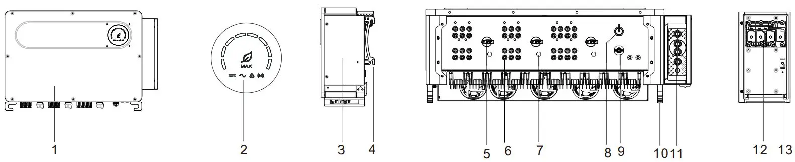
- Front panel
- LED indicator
- Junction box
- Support frame
- DC switch
- PV terminal
- Vent valve
- USB port
- COM port
- Anti-collision angle
- Waterproof silicone pad
- AC terminal block
- Grounding copper bar
Note
- This document is for quick installation guidance only, please refer to User Manual for more details.
- Growatt shall not be liable for any damage resulting from unproper installation.
Installation
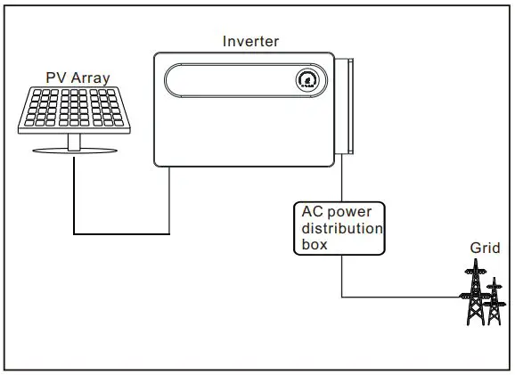
System overview
Installation requirements
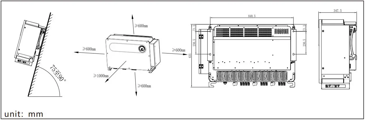
Wall mounting
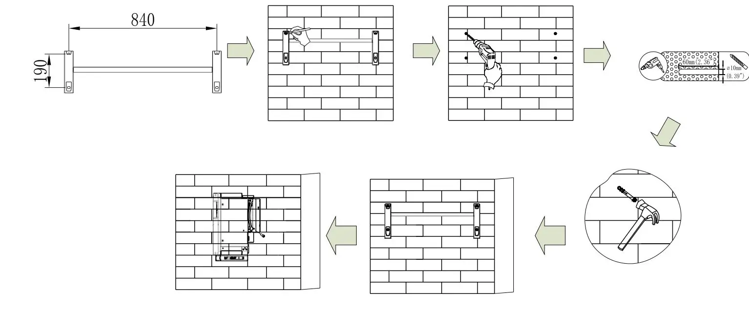
- unit: mm
Note: Please choose a wall with a thickness of more than 100mm, and use a φ10 drill bit to drill a hole with a depth of 60mm in the wall mount installation space.
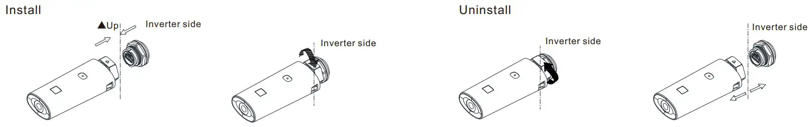
Communication Module Installation
Electrical connection
Please prepare the cable before connecting as follows.
| No. | Cable name | Type | Recommend model (Copper wire) | Recommend model (AL. wire) |
| 1 | Protective grounding wire | Single multi-core yellow-green wire | 50mm² | 70mm² |
| 2 | AC output wire | Single multi-core wire | 70mm² – 240mm² | 95mm² – 240mm² |
| 3 | PV input wire | Single multi-core wire | 4mm² – 6mm² | / |
| 4 | Communication wire | RS485 | / | / |
Note
- Please make sure all switches are in “OFF” position before wiring. For personal safety, please do not operate with electricity.
- If the diameter of the cable does not match the terminal, or the cable is aluminum wire, please contact our after-sales personnel.
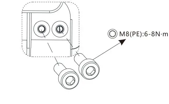
Grounding
Note
- The built-in grounding copper bar is only used as an equipotential connection point for the protective ground. It cannot be used as a substitute for the protective grounding point of the inverter housing.
- It is recommended that the PE cable of the inverter be connected to a nearbyground point. For a system with multiple inverters connected in parallel,connect the ground points of all inverters to ensure equipotential connections to ground cables.
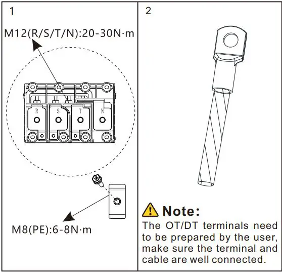
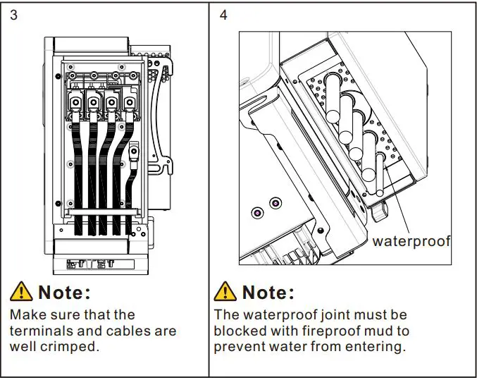
AC output connection
DC Connection
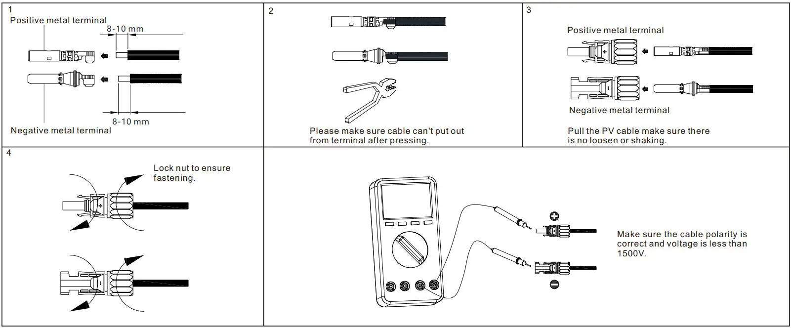
PV input terminal installation
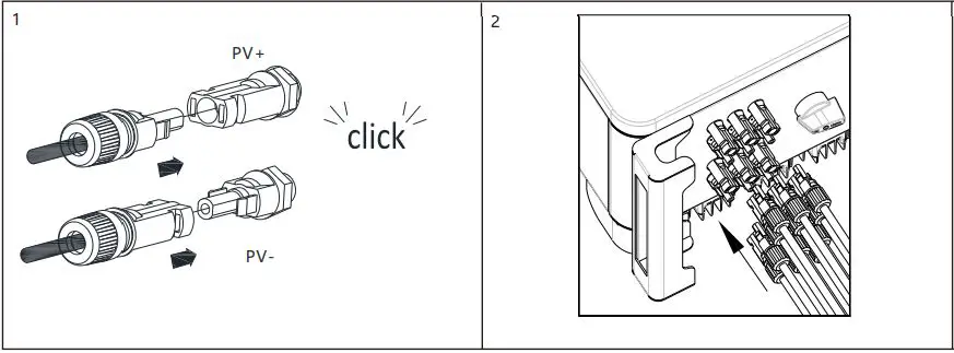
Plug in PV terminal
Note
- Before installing the PV terminal, please double- check that the PV input voltage and current do not exceed the MPPT limits.
- When installing the PV terminal, pay attention to the difference between the positive and negative poles and the one-toone correspondence between the terminals and the machine.
- There is a “click” sound when the terminal is connected,please gently pulling the PV wire to make sure there is no loose or pulling off.
Communication cable installation
RS485 installation
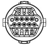
| No. | Description | No. | Description |
| 1/2 | 485-1 Shield | 9 | DRM1/5 | |
| 3 | 485-1 A1 | 10 | DRM2/6 | |
| 4 | 485-1 B1 | 11 | DRM3/7 | |
| 5 | 485-1 A1 | 12 | DRM4/8 | |
| 6 | 485-1 B1 | 13 | REE/GEN | |
| 7 | 485-2 A1 | 14 | DRM0/COM | |
| 8 | 485-2 B1 | 15 | 485-1 matching resistance | |
| Note:When mult-parallel inverter are installed,matching resistors need to be introduced. | ||||
USB installation
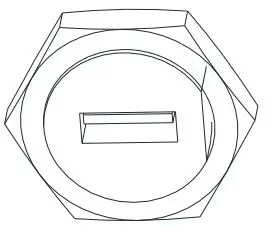
- USB interface can be used to connect USB to WIFI module /GPRS module.
Mult-parallel inverter installation
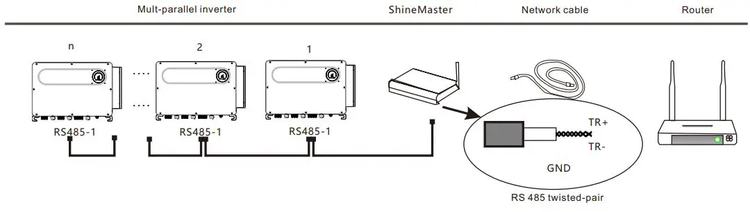
Note: When multiple inverters communicate in parallel (n>1, n is recommended not to exceed 32), short-circuit the pins 15/16 of the last inverter through a wire to introduce matching resistance.
Post-installation check
| No. | Acceptance criteria | No. | Acceptance criteria |
| 1 | The inverter is installed correctly, firmly and reliably. | 6 | The RS485 communication cable is installed correctly and firmly. |
| 2 | The ground wire connected well and the connection is firm and reliable. | 7 | The cable tie port is trimmed well without leaving sharp corners,meets the requirements of the user. |
| 3 | All switches are in the OFF state. | 8 | All exposed terminals are well protected and there are no vacant ports. |
| 4 | All wiring is correct and securely connected. | 9 | Pay attention to clean up all construction residues. |
| 5 | The wiring of the cable is reasonable, meets the requirements, and there is no phenomenon of broken skin. |
Power on and off steps
Note: Before powering on, please make sure that all voltage ranges are within the working range of the machine, otherwise the machine may be damaged. Follow the steps below to switch on and off:
- Close the switch between the PV and the inverter.
- Close the switch between the power grid and the inverter.
- If you need to set the inverter, please refer to the inverter user manual for details.
- The shutdown steps are opposite to the above order.
Status of PV grid inverter
Customer can read more information by LED.Follow are the instruction of LED
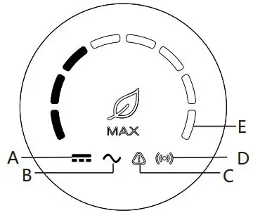
| Indicator | Function | State | Instructions | ||
| A | PV voltage indicator | Green light is always on | PV voltage≥190V | ||
| B | AC voltage indicator | Green light is always on | Inverter is in the grid state | ||
| Green light is flashing | Inverter status | grid-connected | countdown/fault | ||
| C | Alarm / fault indicator | Red light is flashing slowly | Inverter warning | ||
| Red light is always on | Inverter fault | ||||
| D | Communication indicator | Green light is always on | The inverter communicate normally | ||
| E | Power indicator | Green light is always on | The eight LEDs represent the power of the inverter | ||
| Fault code indicator | Green light is always on | For the detail fault code,please refer to the manual | |||
Service And Contact
Shenzhen Growatt New Energy Co., Ltd
- 4-13/F, Building A,Sino-German(Europe) Industrial Park, Hangcheng Ave, Bao’an District, Shenzhen, China
- Т: +86 0755 2747 1942
- E: [email protected]
- W: www.ginverter.com
Download Manual


- Growatt New Energy


