
Quick Installation Guide
Hybrid Inverter
ET Series and ET Plus+ Series
(GW5KL-ET | GW6KL-ET | GW8KL-ET | GW10KL-ET | GW5K-ET | GW6.5K-ET | GW8K-ET | GW10K-ET | GW5KN-ET | GW6.5KN-ET | GW8KN-ET | GW10KN-ET)
AC-Coupled Inverter
BT Series
(GW5K-BT | GW6K-BT | GW8K-BT | GW10K-BT)
V1.1-2022-04-28
Safety Precautions
General Disclaimer
• The information in this quick installation guide is subject to change due to product updates or other reasons. This guide cannot replace the product labels or the safety precautions in the user manual unless otherwise specified. All descriptions here are for guidance only.
• Before installations, read through the quick installation guide. For additional information, please see the user manual.
• All operations should be performed by trained and knowledgeable technicians who are familiar with local standards and safety regulations.
• Check the deliverables for correct model, complete contents, and intact appearance. Contact the manufacturer if any damage is found or any component is missing.
• Use insulating tools and wear personal protective equipment when operating the equipment to ensure personal safety. Wear anti-static gloves, clothes, and wrist strip when touching electronic components to protect the inverter from damage. The manufacturer shall not be liable for any damage caused by static electricity.
• Strictly follow the installation, operation, and configuration instructions in this guide and user
manual. The manufacturer shall not be liable for equipment damage or personal injury if you do not follow the instructions. For more warranty details, please visit https://en.goodwe.com/ warranty.
Safety Disclaimer

Warning
DC Side:
- Ensure the component frames and the bracket system are securely grounded.
- Connect the DC cables using the delivered PV connectors. The manufacturer shall not be
liable for equipment damage if other connectors are used. - Ensure the DC cables are connected tightly, securely, and correctly. Inappropriate wiring
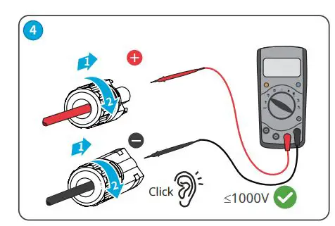
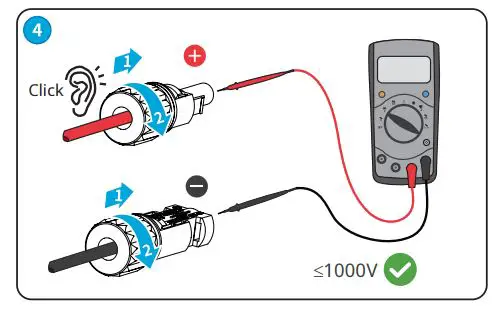
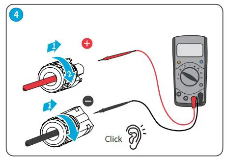
may cause poor contacts or high impedances, and damage the inverter. - Measure the DC cable using the multi meter to avoid reverse polarity connection. Also, the
voltage should be under the max DC input voltage. The manufacturer shall not be liable for
the damage caused by reverse connection and extremely high voltage. - To avoid shock hazards, ensure the minimum impedance of the PV string to the ground
exceeds R, R=Max. Input Voltage (V)/30mA. - Keep the battery off, and the inverter disconnects with PV panels and other AC power
before connecting the battery and the inverter. The rated voltage of the battery should meet specifications of the inverter. - The PV modules used with the inverter must have an IEC61730 class A rating.
AC Side:
- The voltage and frequency at the connecting point should meet the on-grid requirements.
- Additional protective devices like circuit breakers or fuses are recommended on the AC side. Specification of the protective device should be at least 1.25 times the rated AC output rated current.
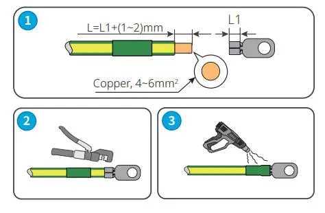
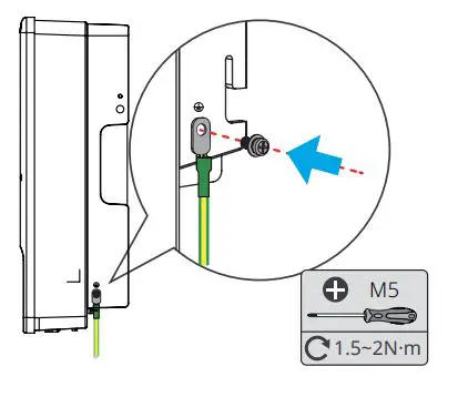
- PE cable of the inverter must be connected firmly.
- You are recommended to use copper cables as AC output cables. If you prefer aluminum cables, remember to use copper to aluminum adapter terminals.
Product:
- Do not apply mechanical load to the terminals, otherwise the terminals can be damaged.
- All labels and warning marks should be visible after the installation. Do not scrawl, damage,
or cover any label on the device. - Do not touch the running equipment to avoid being hurt as its temperature may exceed 60℃. Do not install the equipment at a place within children’s reach.
- Unauthorized dismantling or modification may damage the equipment, the damage is not covered under the warranty.
- Do not start the BACK-UP function if the inverter is not connected to the battery.
- If there is any radio or wireless communication equipment below 30MHz near the inverter, you have to:
• Install the inverter at least 30m far away from the wireless equipment.
• Add a low pass EMI filter or a multi winding ferrite core to the DC input cable or AC output
cable of the inverter. - Warning labels on the inverter are as follows
 | HIGH VOLTAGE HAZARD. Disconnect all incoming power and turn off the product before working on it. |  | Delayed discharge. Wait 5 minutes after power off until the components are completely discharged. |
 | Read through the guide before working on this device.. |  | Potential risks exist. Wear proper PPE before any operations |
 | High-temperature hazard. Do not touch the product under operation to avoid being burnt. |  | Grounding point. Indicates the position for connecting the PE cable. |
 | CE marking |  | Do not dispose of the inverter as household waste. Discard the product in compliance with local laws and regulations, or send it back to the manufacturer |
Check before Power-on
| NO | Check Item |
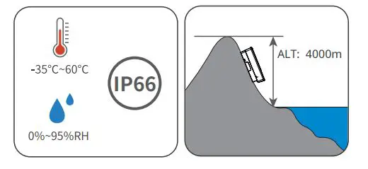
| 1 | The product is firmly installed at a clean place that is well-ventilated and easy-to operate |
| 2 | The PE, DC input, AC output, and communication cables are connected correctly and securely. |
| 3 | Cable ties are intact, routed properly and evenly. |
| 4 | Unused ports and terminals are sealed. |
| 5 | The voltage and frequency at the connection point meet the inverter grid connection requirements. |
EU Declaration of Conformity
Good We Technologies Co., Ltd. hereby declares that the inverter with wireless communication
modules sold in the European market meets the requirements of the following directives:
- Radio Equipment Directive 2014/53/EU (RED)
- Restrictions of Hazardous Substances Directive 2011/65/EU and (EU) 2015/863 (RoHS)
- Waste Electrical and Electronic Equipment 2012/19/EU
- Registration, Evaluation, Authorization and Restriction of Chemicals (EC) No 1907/2006 (REACH)
Good We Technologies Co., Ltd. hereby declares that the inverter without wireless communication
modules sold in the European market meets the requirements of the following directives:
- Electromagnetic compatibility Directive 2014/30/EU (EMC)
- Electrical Apparatus Low Voltage Directive 2014/35/EU (LVD)
- Restrictions of Hazardous Substances Directive 2011/65/EU and (EU) 2015/863 (RoHS)
- Waste Electrical and Electronic Equipment 2012/19/EU
- Registration, Evaluation, Authorization and Restriction of Chemicals (EC) No 1907/2006 (REACH)
You can download the EU Declaration of Conformity on https://en.goodwe.com.
LED Indicators
| Indicator | Status | Explanation |
| SYSTEM | ON = The system is ready. | |
| BLINK = The system is starting. | ||
| OFF =The system is not working. | ||
| BACK-UP | ON = Back-up is ready / power available. | |
| OFF = Back-up is off / power not available. | ||
| BATTERY | ON = The battery is charging. | |
| BLINK 1 = The battery is discharging. | ||
| BLINK 2 = The battery is low / soc is low. | ||
| OFF = The battery is disconnected / not active. | ||
| GRID | ON = The grid is active and connected. | |
| BLINK = The grid is active but not connected. | ||
| OFF = The grid is not active. | ||
| ENERGY | ON = Consuming energy from grid / buying. | |
| BLINK 1 = Supplying energy to grid / zeroing. | ||
| BLINK 2 = Supplying energy to grid / selling. | ||
| OFF = The grid is not connected or the system is not working | ||
| COM | ON = Both BMS communication and meter communication are ok. | |
| BLINK 1 = BMS communication fails; meter communication is ok. | ||
| BLINK 2 = BMS communication is ok; meter communication fails. | ||
| OFF = BMS communication and meter communication fail. | ||
| Wi-Fi | ON = Wi-Fi connected / active. | |
| BLINK 1 = Wi-Fi is resetting. | ||
| BLINK 2 = Wi-Fi is not connected to the router. | ||
| BLINK 4 = Wi-Fi server problem. | ||
| OFF = Wi-Fi is not active | ||
| FAULT | ON = A fault has occured. | |
| BLINK 1 = Back-up output overload / reduce load. | ||
| OFF = No fault. |
Introduction
Product Introduction
Parts
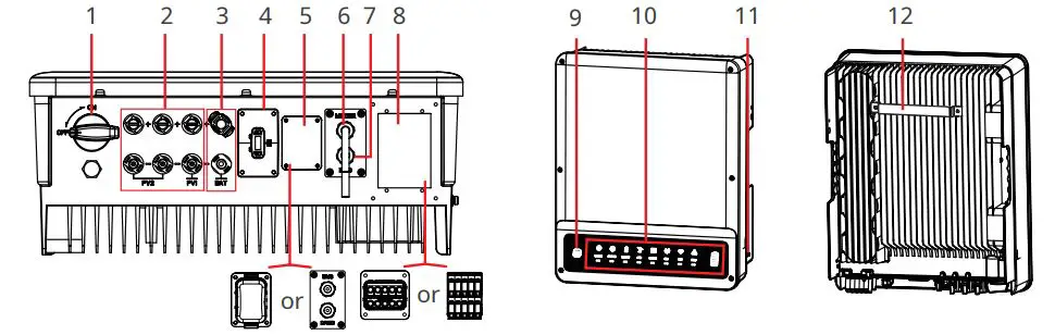
- DC Switch [1]
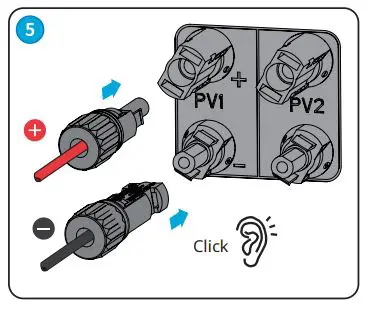
- PV Input Terminal (PV+/PV-)[2]
- Battery Terminal (BAT+/BAT-)
- Communication Module Port (WiFi or Bluetooth)[3]
- COM Terminal
- METER Communication Port
- Communication Port(BMS or EMS)[4]
- AC Terminal (ON-GRID and BACKUP)
- Wi Fi Reset
- Indicators
- PE Terminal
- Mounting Plate
[1] For ET series and ET Plus+ series only. GW5KL-ET, GW6KL-ET, GW8KL-ET,GW10KL-ET: optional.
[2] For ET series and ET Plus+ series only. GW8KL-ET and GW10KL-ET: 2 x PV+/PV-; 3 x PV+/PV- in Australia.
[3] Bluetooth for ET series and ET Plus+ series only.
[4] Subject to actual silkscreen.
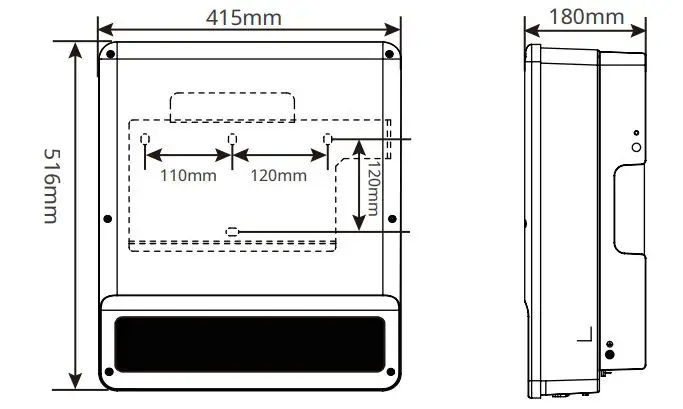
Dimensions
Inverter Installation
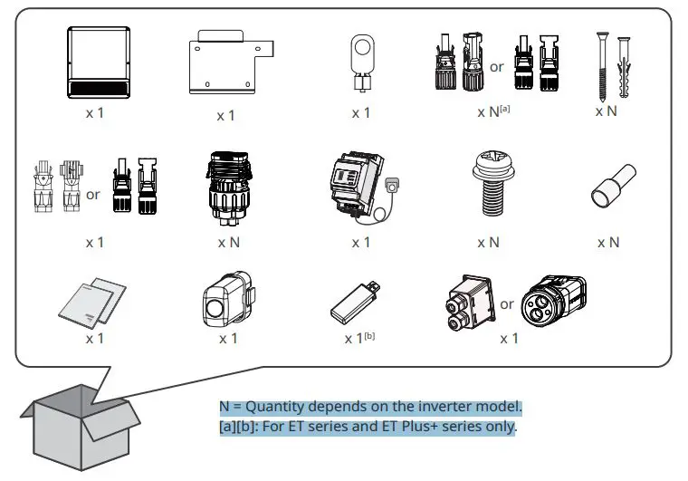
N = Quantity depends on the inverter model.
[a][b]: For ET series and ET Plus+ series only
Space Requirements
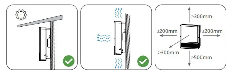
Angle Requirements
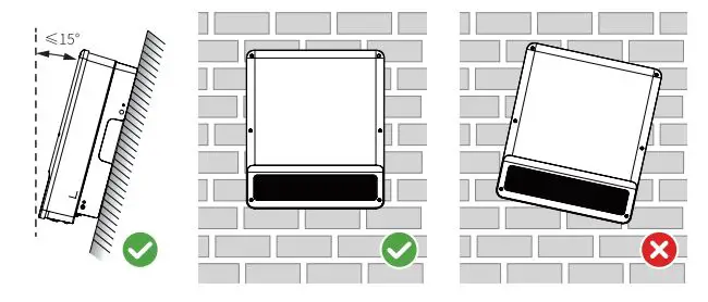
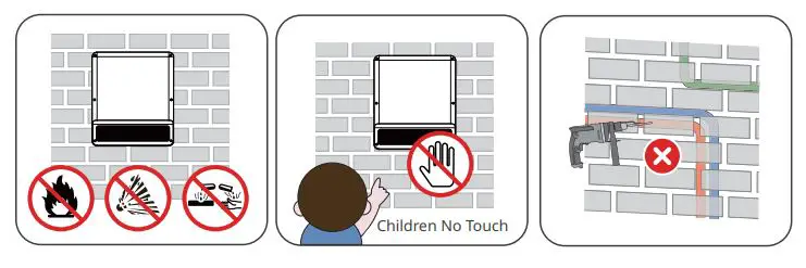
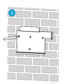
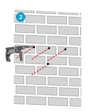
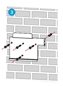
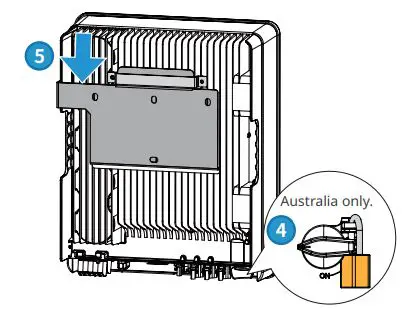
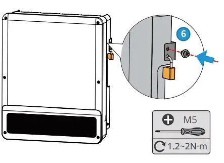
Installing the Inverter
Electrical Connection
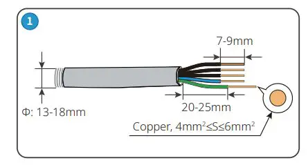
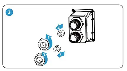
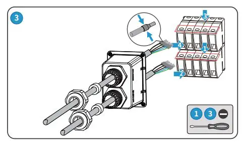
AC Cable (ON-GRID&BACK-UP)
Type One
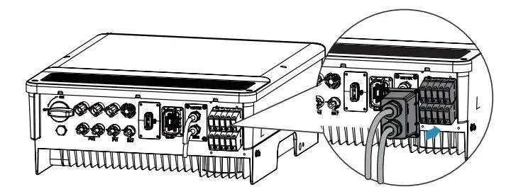
Type Two

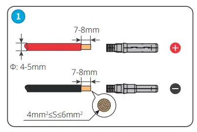
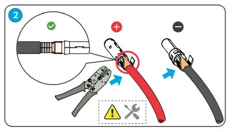
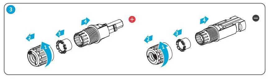
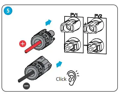
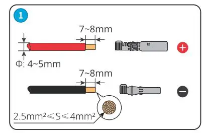
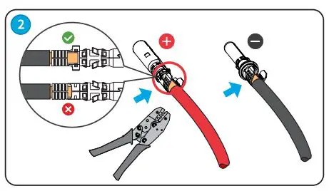
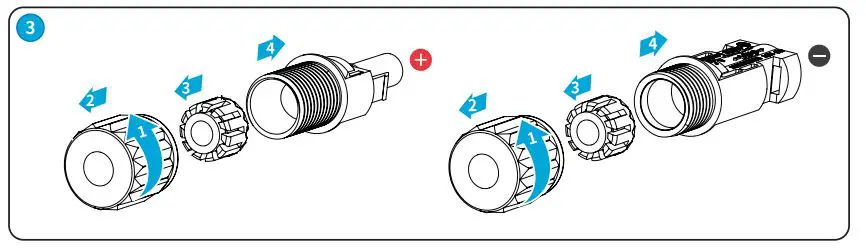
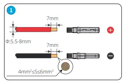
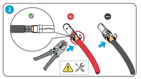
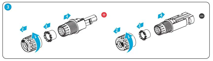
DC Cable (PV)
• For ET series and ET Plus+ series.
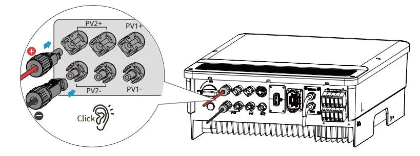
MC4
Devalan
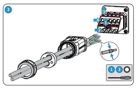
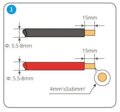
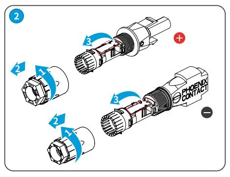
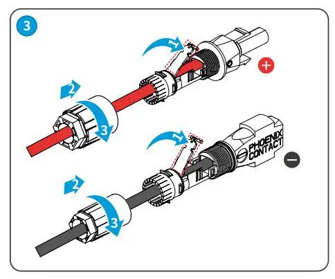
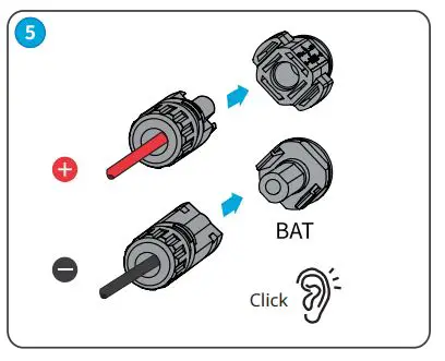
Battery Cable (BATTERY)
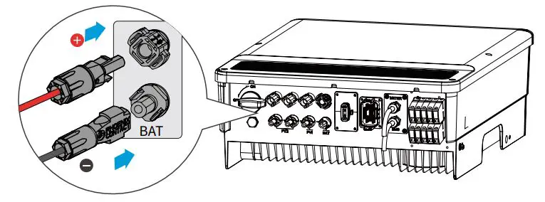
Phoenix
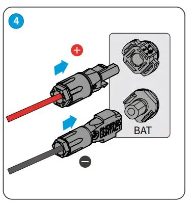
MC4
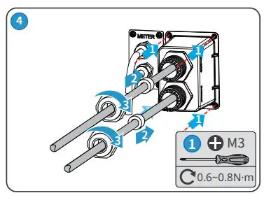
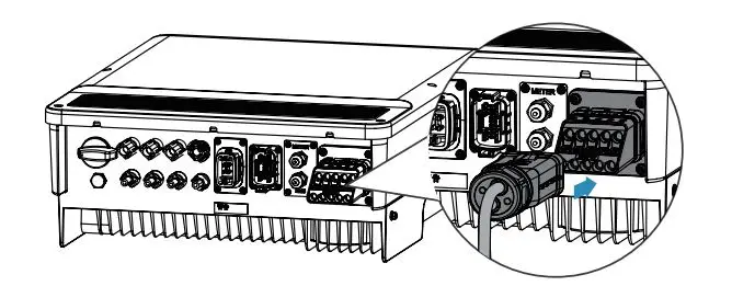
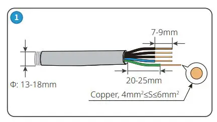
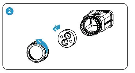
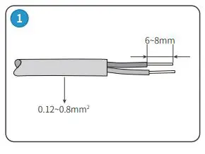
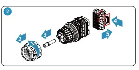
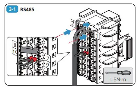
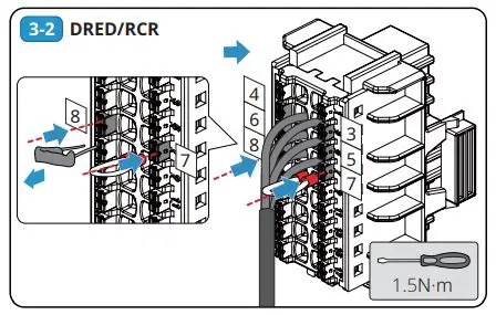
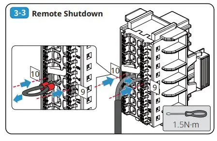
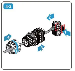
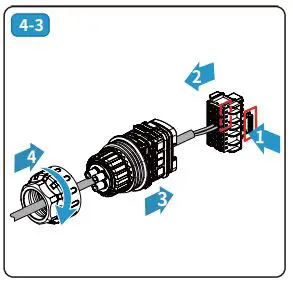
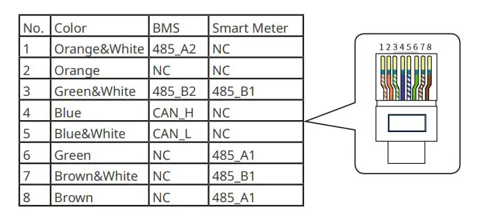
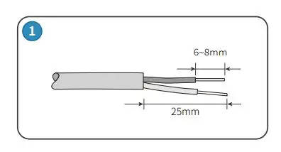
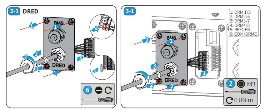
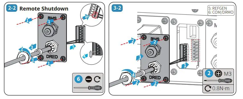
Communication Connection
Type One
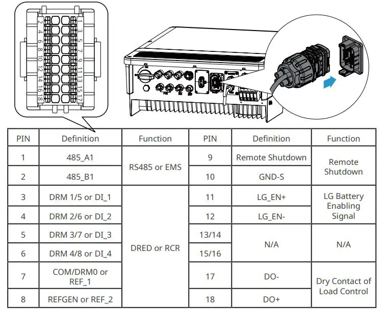
Example:
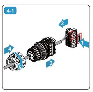
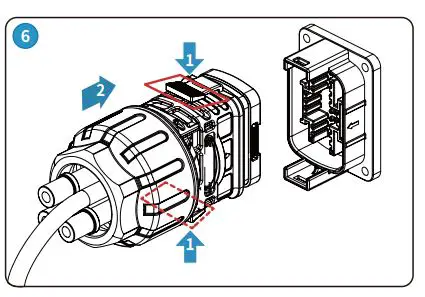
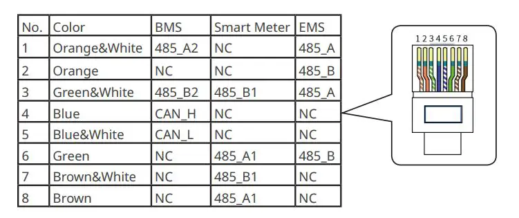
BMS or Smart Meter
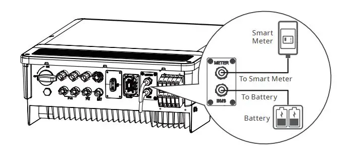
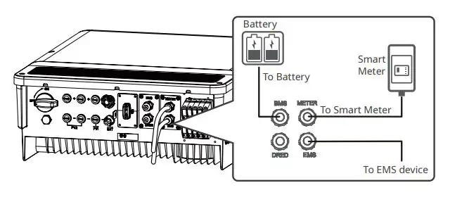
Type Two
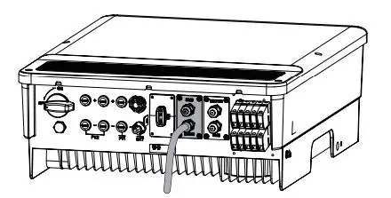
Smart Meter, BMS and EMS
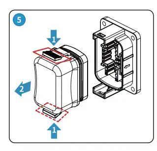
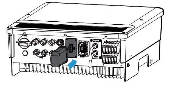
Communication Module
Wi Fi Kit, Bluetooth, Wi-Fi/LAN Kit module: optional
Power On and Off
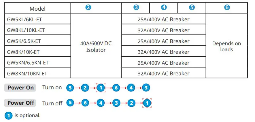
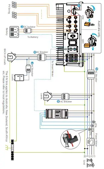
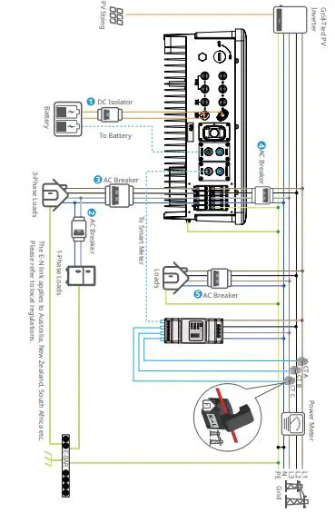
Recommended Circuit Breaker
ET Series and ET Plus+ Series
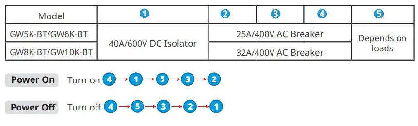
BT Series
Commissioning and Monitoring
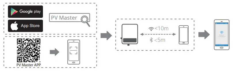
Commissioning via PV Master APP
Monitoring via SEMS Portal App
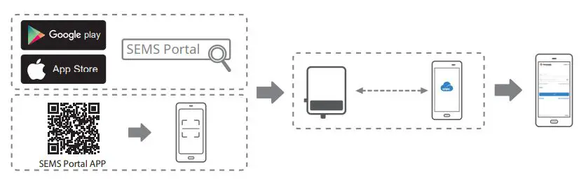
For more detailed instructions, scan the QR codes below


Good We Technologies Co., Ltd.
No. 90 Zijin Rd., New District, Suzhou, 215011, China
www.goodwe.com
[email protected]