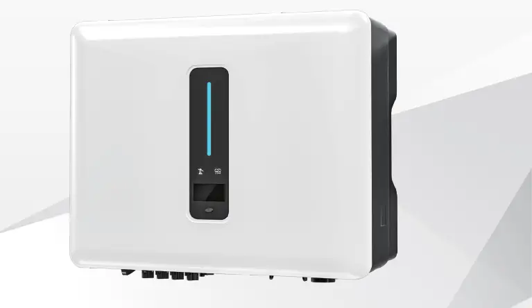
watt sonic 4-5-6-8-10-12KW-25A-3P Gen3 Hybrid Inverter
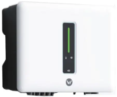
Product Information: Watt sonic Gen3 Hybrid Inverter
The Watt sonic Gen3 Hybrid Inverter is available in different models including 4/5/6/8/10/12KW-25A-3P and 10/12/15/20KW-40A-3P.
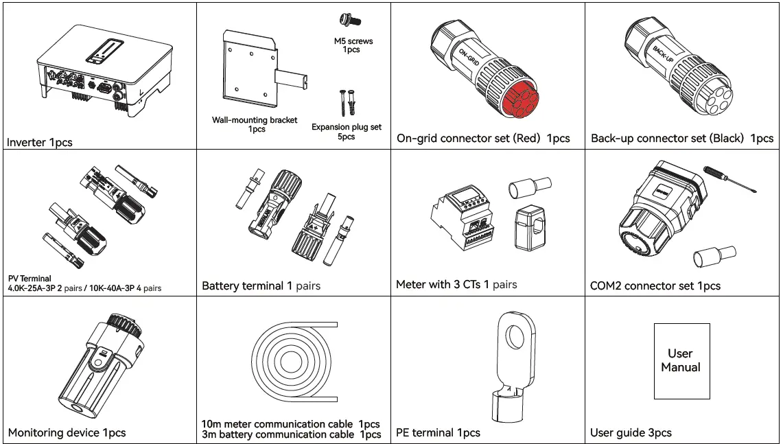
The inverter comes with a wall-mounting bracket, expansion plug set, on-grid connector set (Red), back-up connector set (Black), PV Terminal 4.0K-25A-3P 2 pairs / 10K-40A-3P 4 pairs, battery terminal 1 pair, meter with 3 CTs, monitoring device, 10m-meter communication cable, 3m battery communication cable, and PE terminal. It can be used for both on-grid and back-up power supply.
Product Usage Instructions: Watt sonic Gen3 Hybrid Inverter
- Before installing the Watt sonic Gen3 Hybrid Inverter, check the packing list to ensure all components are included.
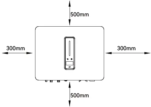
- Determine the installation location based on the provided electrical wiring diagram and the available installation space of at least 300mm x 500mm x 300mm.
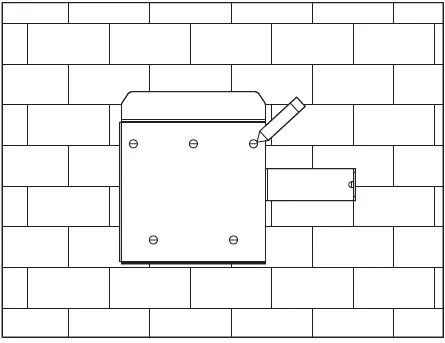
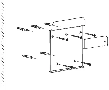
- Mark the position and drill holes for the wall-mounting bracket.
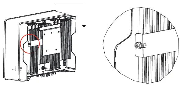
- Fix the wall bracket and mount the inverter on it.
- Connect the PV modules, AC cable, and battery power cable as per the cable requirements provided in the manual.
- Connect the monitoring device and the meter with 3 CTs using the provided communication cables.
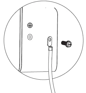
- Connect the grounding terminal to the PE terminal.
- Finally, connect the Watt sonic Gen3 Hybrid Inverter to the utility grid and switch it on.
For further assistance or to purchase terminals of other specifications, please contact Watt sonic.
Installation
Check Packing List
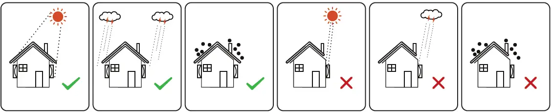
- Installation Location

- Installation Space

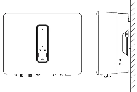
- Installation Angle

- Mark the position and drill holes

- Fix wall bracket

- Mounting inverter

- Grounding terminal connection

Electrical Connection
Cable Requirements
| Cable types AC cable | Cable requirements | |
| Outside diameter 13.0-18.0 mm | Conductor core section 2.5-10.0 mm² | |
| PV cable | 5.9-8.8 mm | 2.5-4.0 mm² |
| Battery power cable | 5.0-8.0 mm | 10 mm² |
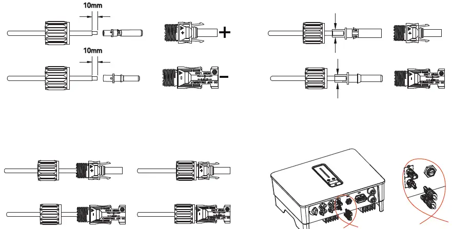
AC Connector: Please distinguish the on-grid and back-up connector, On-grid connector is red and Back-up connector is Black.
Battery power cable: If the conductor core of the battery cable is too small, which may cause poor contact between the terminal and the cable, please use the cable specified in the above table, or contact Watt sonic to purchase terminals of other specifications.
Electrical wiring diagram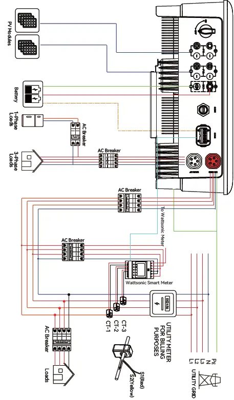 AC Connection
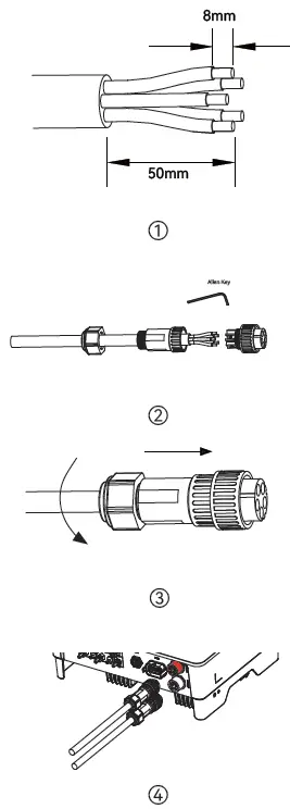 Monitoring Device Installation
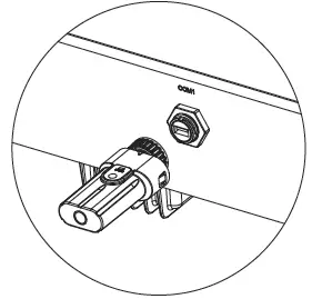 Meter and CT connection
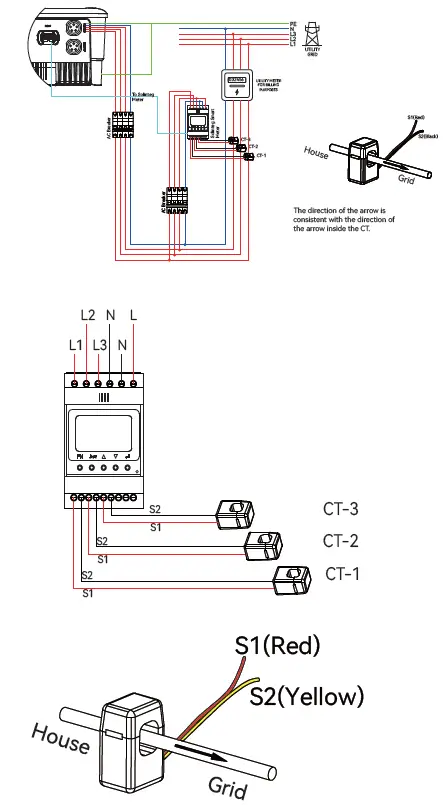 Meter terminals definition
| No. | Definition | Function |
| 5 | L1-S1 | To detect the CT current |
| 6 | L1-S2 | |
| 7 | L2-S1 | |
| 8 | L2-S2 | |
| 9 | L3-S1 | |
| 10 | L3-S2 | |
| 1 | L1 | L1/L2/L3/N connect to grid to detect power grid voltage |
| 2 | L2 | |
| 3 | L3 | |
| 4 | N | |
| 12 | L | Power supplied from grid |
| 13 | N | |
| RS485 | RS485 | Communicate with inverter |
Communication Connection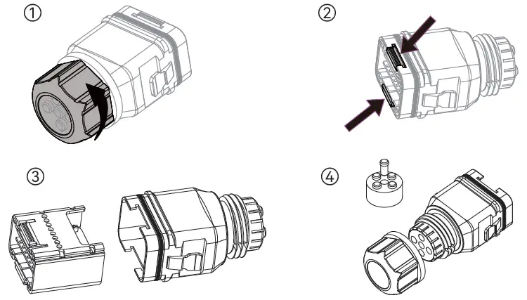
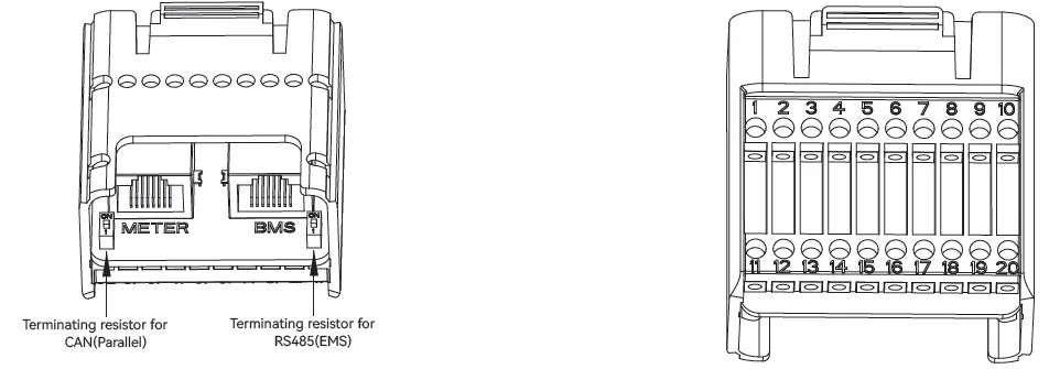
| Pin | Definition | Function |
| RJ45-1 | RS 485 | Communicate with Meter |
| RJ45-2 | CAN | Communicate with BMS |
| 1 | COM | Multifunction Relay |
| 2 | NO (Normally Open) | |
| 3-4 | / | Reserved |
| 5 | DRM4/8 | DRED For Australia and New Zealand |
| 6 | DRM3/7 | |
| 7 | DRM2/6 | |
| 8 | DRM1/5 | |
| 15 | COM D/0 | |
| 16 | REF D/0 | |
| 9-10 | / | Reserved |
| 11 | Fast stop + | Fast stop |
| 12 | Fast stop – | |
| 13 | 485 B1 | EMS |
| 14 | 485 A1 | |
| 17 | CANL_P | CAN for parallel connection of inverters |
| 18 | CANH_P | |
| 19-20 | / | Reserved |
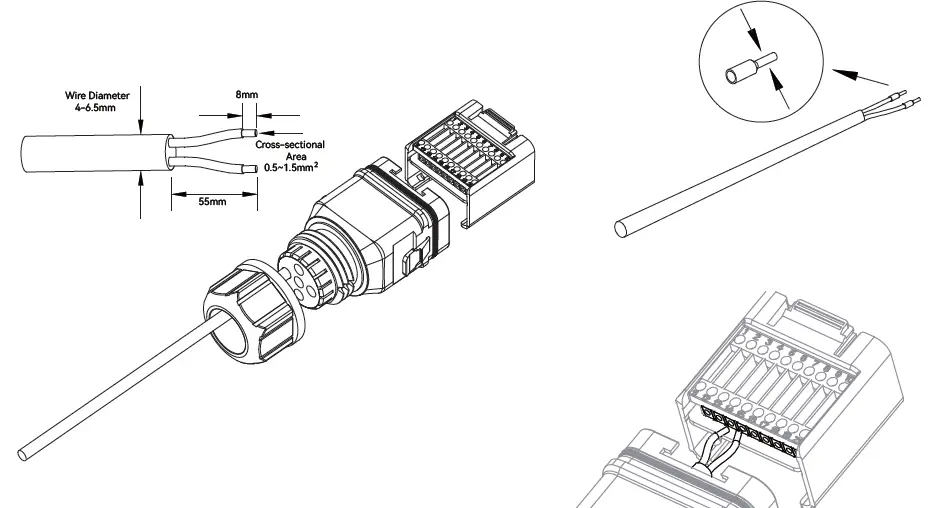
- Connect the Meter and BMS communication cables

- Connect other cables

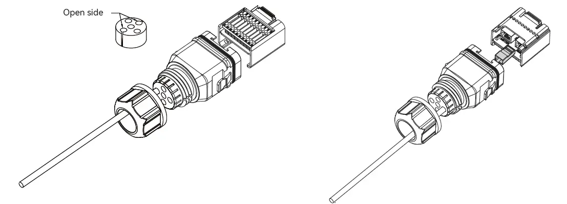
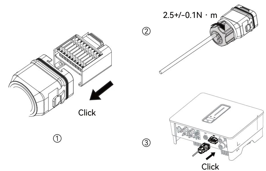
- Installing the COM Connector

PV string connection
PV Max. Input voltage is 950V without battery, or 850V with battery, otherwise inverter will be waiting.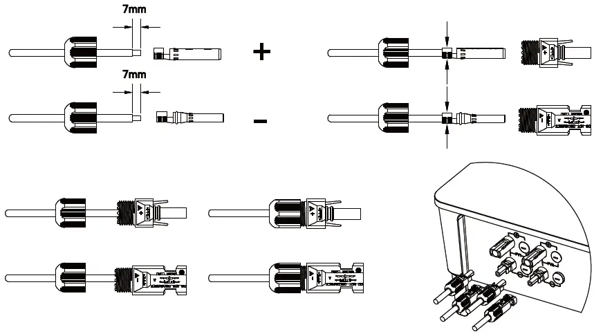 Power cable of the battery connection