VENTS VCUN Centrifugal Fan User Manual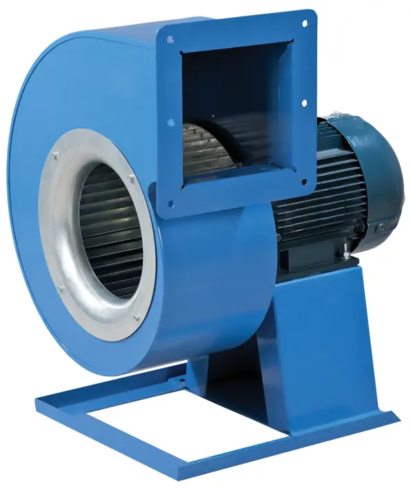
SAFETY REQUIREMENTS
- Please read the user’s manual carefully prior to installing and operating the unit.
- All user’s manual requirements as well as the provisions of all the applicable local and national construction, electrical, and technical norms and standards must be observed when installing and operating the unit.
- The warnings contained in the user’s manual must be considered most seriously since they contain vital personal safety information.
- Failure to follow the rules and safety precautions noted in this user’s manual may result in an injury or unit damage.
- After a careful reading of the manual, keep it for the entire service life of the unit.
- While transferring the unit control, the user’s manual must be turned over to the receiving operator.
UNIT INSTALLATION AND OPERATION SAFETY PRECAUTIONS
- Disconnect the unit from power mains prior to any installation operations.
- Unpack the unit with care.
- The unit must be grounded!
- While installing the unit, follow the safety regulations specific to the use of electric tools.
- Do not change the power cable length at your own discretion.
- Do not bend the power cable.
- Avoid damaging the power cable.
- Do not put any foreign objects on the power cable.
- Do not lay the power cable of the unit in close proximity to heating equipment.
- Do not use damaged equipment or cables when connecting the unit to power mains.
- Do not operate the unit outside the temperature range stated in the user’s manual.
- Do not operate the unit in aggressive or explosive environments.
- Do not touch the unit controls with wet hands.
- Do not carry out the installation and maintenance operations with wet hands.
- Do not wash the unit with water.
- Protect the electric parts of the unit against ingress of water.
- Do not allow children to operate the unit.
- The unit is allowed to be used by children aged from 8 years oldand above and persons with reduced physical, sensory, or mental capabilities or no experience and knowledge provided that they have been given supervision or instruction regarding safe use of the unit and understand the risks involved.
- Disconnect the unit from power mains prior to any technical maintenance.
- Do not store any explosive or highly flammable substances in close proximity to the unit.
- When the unit generates unusual sounds, odour, or emits smoke, disconnect it from power supply and contact the Seller.
- Do not open the unit during operation.
- Do not direct the air flow produced by the unit towards open flame or ignition sources.
- Do not block the air duct when the unit is switched on.
- In case of continuous operation of the unit, periodically check the security of mounting.
- Do not sit on the unit and avoid placing foreign objects on it.
- Use the unit only for its intended purpose.
 THE PRODUCT MUST BE DISPOSED SEPARATELY AT THE END OF ITS SERVICE LIFE.
DO NOT DISPOSE THE UNIT AS UNSORTED DOMESTIC WASTE.
PURPOSE
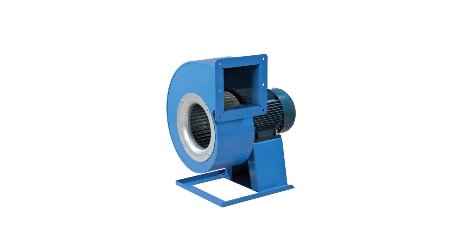
Centrifugal fans in a scroll casing are designed for supply and exhaust ventilation of domestic, public and industrial premises.
The unit is rated for continuous operation.
Transported air must not contain any flammable or explosive mixtures, evaporation of chemicals, sticky substances, fibrous materials, coarse dust, soot and oil particles or environments favourable for the formation of hazardous substances (toxic substances, dust, pathogenic germs).
![]() THE UNIT SHOULD NOT BE OPERATED BY CHILDREN OR PERSONS WITH REDUCED PHYSICAL, MENTAL, OR SENSORY CAPACITIES, OR THOSE WITHOUT THE APPROPRIATE
THE UNIT SHOULD NOT BE OPERATED BY CHILDREN OR PERSONS WITH REDUCED PHYSICAL, MENTAL, OR SENSORY CAPACITIES, OR THOSE WITHOUT THE APPROPRIATE
TRAINING.
THE UNIT MUST BE INSTALLED AND CONNECTED ONLY BY PROPERLY QUALIFIED PERSONNEL AFTER THE APPROPRIATE BRIEFING.
THE CHOICE OF UNIT INSTALLATION LOCATION MUST PREVENT UNAUTHORISED ACCESS BY UNATTENDED CHILDREN.
DELIVERY SET
| Name | Number |
| Fan | 1 pc. |
| User’s manua | 1 pc. |
| Mounting bracket | 1 pc. |
| Packing box | 1 pc. |
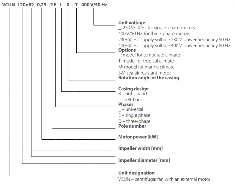
DESIGNATION KEY
TECHNICAL DATA
The fan is designed for ambient temperature ranging from +1 °C up to +40 °C and relative humidity up to 80 %.
The fan design is constantly being improved, thus some models may be slightly different from those described in this manual.
The unit is rated as a Class I electrical appliance.
Hazardous parts access and water ingress protection rating:
- for VCUN fans – IP55.
![]() NEVER TEST RUN OR OPERATE THE FAN, WHICH IS NOT CONNECTED TO THE VENTILATION SYSTEM, IF THE AIR FLOW RATE AND THE CURRENT CONSUMPTION EXCEED THE MAXIMUM VALUE FOR THE GIVEN STANDARD SIZE (SEE TECHNICAL PARAMETERS ON THE LABEL), AND IN THE ABSENCE OF THERMAL PROTECTION OF THE MOTOR
NEVER TEST RUN OR OPERATE THE FAN, WHICH IS NOT CONNECTED TO THE VENTILATION SYSTEM, IF THE AIR FLOW RATE AND THE CURRENT CONSUMPTION EXCEED THE MAXIMUM VALUE FOR THE GIVEN STANDARD SIZE (SEE TECHNICAL PARAMETERS ON THE LABEL), AND IN THE ABSENCE OF THERMAL PROTECTION OF THE MOTOR
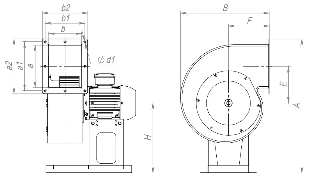
Overall dimensions and position options of the VCUN fan casing
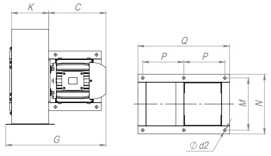
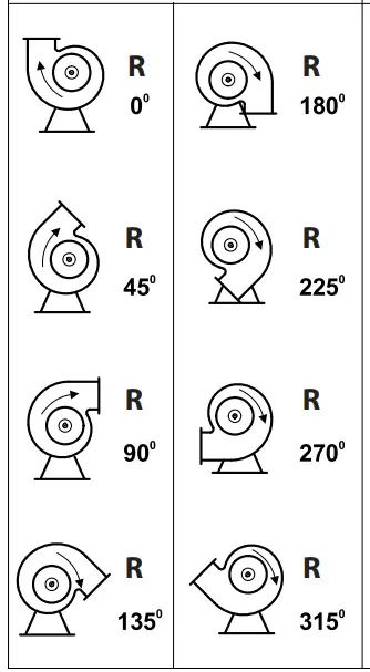
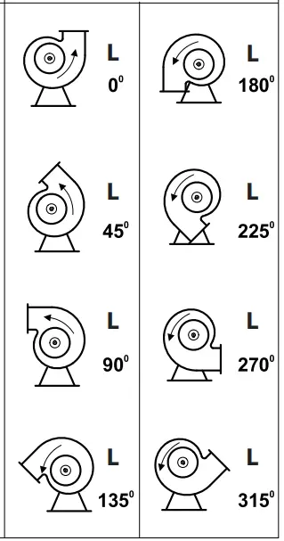
POSSIBLE VARIANTS OF THE VCUN FAN CASING POSITIONS
(View on the supply side)
| Impeller rotation rightwards | Impeller rotation leftwards |
 |  |
| Fan model | Dimensions [mm] | Weight [kg] | ||||||||||||||||||||
| A | B | C | E | F | G | H | K | M | N | Q | P | a | b | a1 | a2 | b1 | b2 | d1 | d2 | |||
| VCUN 120х62-0,25-2D | 329 | 211 | 192 | 82 | 103 | 306 | 175 | 93 | 174 | 191 | 268 | 120 | 93 | 86 | 123 | 145 | 145 | 135 | 8 | 7 | 7.3 | |
| VCUN 120х62-0,25-2E | 329 | 211 | 192 | 82 | 103 | 306 | 175 | 93 | 174 | 191 | 268 | 120 | 93 | 86 | 123 | 145 | 145 | 135 | 8 | 7 | 7.3 | |
| VCUN 146х62-0,37-2D | 385 | 249 | 220 | 100 | 118 | 345 | 203 | 102 | 174 | 191 | 293 | 135 | 114 | 96 | 141 | 165 | 165 | 149 | 8 | 7 | 9.7 | |
| VCUN 146х62-0,37-2E | 385 | 249 | 220 | 100 | 118 | 345 | 203 | 102 | 174 | 191 | 293 | 135 | 114 | 96 | 141 | 165 | 165 | 149 | 8 | 7 | 10.2 | |
| VCUN 160х74-0,12-4D | 414 | 275 | 192 | 109 | 132 | 335 | 215 | 120 | 179 | 201 | 305 | 135 | 125 | 112 | 156 | 180 | 180 | 166 | 8 | 9 | 7 | |
| VCUN 160х74-0,55-2D | 414 | 275 | 220 | 109 | 132 | 362 | 215 | 120 | 179 | 201 | 305 | 135 | 125 | 112 | 156 | 180 | 180 | 166 | 8 | 9 | 7.7 | |
| VCUN 160х74-0,55-2E | 414 | 275 | 220 | 109 | 132 | 362 | 215 | 120 | 179 | 201 | 305 | 135 | 125 | 112 | 156 | 180 | 180 | 166 | 8 | 9 | 8 | |
| VCUN 180х74-0,18-4D | 455 | 304 | 192 | 123 | 143 | 339 | 235 | 123 | 199 | 221 | 345 | 150 | 141 | 116 | 171 | 195 | 195 | 170 | 8 | 9 | 8 | |
| VCUN 180х74-1,1-2D | 455 | 304 | 237 | 123 | 143 | 383 | 235 | 123 | 199 | 221 | 345 | 150 | 141 | 116 | 171 | 195 | 195 | 170 | 8 | 9 | 16 | |
| VCUN 180х74-0,25-4E | 455 | 304 | 220 | 123 | 143 | 366 | 235 | 123 | 199 | 221 | 345 | 150 | 141 | 116 | 171 | 195 | 195 | 170 | 8 | 9 | 9.5 | |
| VCUN 180х74-1,1-2E | 455 | 304 | 237 | 123 | 143 | 383 | 235 | 123 | 199 | 221 | 345 | 150 | 141 | 116 | 171 | 195 | 195 | 170 | 8 | 9 | 16 | |
| VCUN 200х92-0,37-4D | 507 | 334 | 220 | 137 | 155 | 389 | 265 | 146 | 220 | 246 | 400 | 175 | 157 | 138 | 187 | 211 | 211 | 192 | 8 | 11 | 10.5 | |
| VCUN 200х92-1,1-2D | 507 | 334 | 236 | 137 | 155 | 405 | 265 | 146 | 220 | 246 | 400 | 175 | 157 | 138 | 187 | 211 | 211 | 192 | 8 | 11 | 17.5 | |
| VCUN 200х92-1,5-2D | 507 | 334 | 254 | 137 | 155 | 423 | 265 | 146 | 220 | 246 | 400 | 175 | 157 | 138 | 187 | 211 | 211 | 192 | 8 | 11 | 24 | |
| VCUN 200х92-2,2-2D | 507 | 334 | 279 | 137 | 155 | 448 | 265 | 146 | 220 | 246 | 400 | 175 | 157 | 138 | 187 | 211 | 211 | 192 | 8 | 11 | 28 | |
| VCUN 200х92-0,37-4E | 507 | 334 | 220 | 137 | 155 | 389 | 265 | 146 | 220 | 246 | 400 | 175 | 157 | 138 | 187 | 211 | 211 | 192 | 8 | 11 | 11 | |
| VCUN 200х92-1,1-2E | 507 | 334 | 236 | 137 | 155 | 405 | 265 | 146 | 220 | 246 | 400 | 175 | 157 | 138 | 187 | 211 | 211 | 192 | 8 | 11 | 18 | |
| VCUN 200х92-1,5-2E | 507 | 334 | 254 | 137 | 155 | 423 | 265 | 146 | 220 | 246 | 400 | 175 | 157 | 138 | 187 | 211 | 211 | 192 | 8 | 11 | 24.5 | |
| VCUN 225х102-0,75-4D | 598 | 376 | 236 | 154 | 175 | 428 | 324 | 165 | 254 | 290 | 446 | 200 | 177 | 157 | 211 | 241 | 241 | 221 | 8 | 13 | 19.9 | |
| VCUN 225х102-2,2-2D | 598 | 376 | 279 | 154 | 175 | 472 | 324 | 165 | 254 | 290 | 446 | 200 | 177 | 157 | 211 | 241 | 241 | 221 | 8 | 13 | 30.3 | |
| VCUN 225х102-3,0-2D | 598 | 376 | 315 | 154 | 175 | 508 | 324 | 165 | 254 | 290 | 446 | 200 | 177 | 157 | 211 | 241 | 241 | 221 | 8 | 13 | 38.5 | |
| VCUN 225х102-0,75-4E | 598 | 376 | 236 | 154 | 175 | 428 | 324 | 165 | 254 | 290 | 446 | 200 | 177 | 157 | 211 | 241 | 241 | 221 | 8 | 13 | 20.1 | |
| VCUN 250х102-0,37-6D | 625 | 413 | 236 | 171 | 189 | 439 | 324 | 175 | 254 | 290 | 446 | 200 | 197 | 168 | 231 | 261 | 261 | 232 | 8 | 13 | 21 | |
| VCUN 250х102-1,1-4D | 625 | 413 | 254 | 171 | 189 | 457 | 324 | 175 | 254 | 290 | 446 | 200 | 197 | 168 | 231 | 261 | 261 | 232 | 8 | 13 | 27 | |
| VCUN 250х102-3,0-2D | 625 | 413 | 315 | 171 | 189 | 518 | 324 | 175 | 254 | 290 | 446 | 200 | 197 | 168 | 231 | 261 | 261 | 232 | 8 | 13 | 40 | |
| VCUN 250х102-4,0-2D | 625 | 413 | 334 | 171 | 189 | 537 | 324 | 175 | 314 | 350 | 446 | 200 | 197 | 168 | 231 | 261 | 261 | 232 | 8 | 13 | 47 | |
| VCUN 250х102-5,5-2D | 625 | 413 | 409 | 171 | 189 | 613 | 324 | 175 | 314 | 350 | 446 | 200 | 197 | 168 | 231 | 261 | 261 | 232 | 8 | 13 | 62 | |
| VCUN 250х102-1,1-4Е | 625 | 413 | 254 | 171 | 189 | 457 | 324 | 175 | 254 | 290 | 446 | 200 | 197 | 168 | 231 | 261 | 261 | 232 | 8 | 13 | 27 | |
| VCUN 280х102-0,55-6D | 698 | 463 | 236 | 191 | 213 | 444 | 364 | 180 | 254 | 290 | 446 | 200 | 220 | 171 | 255 | 285 | 285 | 237 | 10 | 13 | 23 | |
| VCUN 280х102-1,5-4D | 698 | 463 | 279 | 191 | 213 | 487 | 364 | 180 | 254 | 290 | 446 | 200 | 220 | 171 | 255 | 285 | 285 | 237 | 10 | 13 | 33.5 | |
| VCUN 280х102-2,2-4D | 698 | 463 | 334 | 191 | 213 | 542 | 364 | 180 | 314 | 350 | 446 | 200 | 220 | 171 | 255 | 285 | 285 | 237 | 10 | 13 | 41.5 | |
| VCUN 280х102-4,0-2D | 698 | 463 | 408 | 191 | 213 | 617 | 364 | 180 | 314 | 350 | 446 | 200 | 220 | 171 | 255 | 285 | 285 | 237 | 10 | 13 | 49 | |
| VCUN 280х102-5,5-2D | 698 | 463 | 408 | 191 | 213 | 617 | 364 | 180 | 314 | 350 | 446 | 200 | 220 | 171 | 255 | 285 | 285 | 237 | 10 | 13 | 64 | |
| VCUN 315х143-0,75-6D | 789 | 520 | 254 | 215 | 239 | 518 | 412 | 231 | 314 | 350 | 557 | 240 | 248 | 221 | 288 | 323 | 323 | 297 | 12 | 13 | 39 | |
| VCUN 315х143-1,1-6D | 789 | 520 | 279 | 215 | 239 | 542 | 412 | 231 | 314 | 350 | 557 | 240 | 248 | 221 | 288 | 323 | 323 | 297 | 12 | 13 | 43 | |
| VCUN 315х143-2,2-4D | 789 | 520 | 333 | 215 | 239 | 598 | 412 | 231 | 314 | 350 | 557 | 240 | 248 | 221 | 288 | 323 | 323 | 297 | 12 | 13 | 51 | |
| VCUN 315х143-3,0-4D | 789 | 520 | 333 | 215 | 239 | 598 | 412 | 231 | 314 | 350 | 557 | 240 | 248 | 221 | 288 | 323 | 323 | 297 | 12 | 13 | 52 | |
| VCUN 315х143-4,0-4D | 789 | 520 | 333 | 215 | 239 | 598 | 412 | 231 | 314 | 350 | 557 | 240 | 248 | 221 | 288 | 323 | 323 | 297 | 12 | 13 | 58 | |
| VCUN 355х143-1,1-6D | 882 | 579 | 279 | 242 | 262 | 550 | 462 | 239 | 314 | 350 | 557 | 240 | 280 | 228 | 320 | 355 | 355 | 304 | 12 | 13 | 48 | |
| VCUN 355х143-1,5-6D | 882 | 579 | 315 | 242 | 262 | 587 | 462 | 239 | 314 | 350 | 557 | 240 | 280 | 228 | 320 | 355 | 355 | 304 | 12 | 13 | 55 | |
| VCUN 355х143-2,2-6D | 882 | 579 | 408 | 242 | 262 | 680 | 462 | 239 | 314 | 350 | 557 | 240 | 280 | 228 | 320 | 355 | 355 | 304 | 12 | 13 | 62 | |
| VCUN 355х143-4,0-4D | 882 | 579 | 408 | 242 | 262 | 680 | 462 | 239 | 314 | 350 | 557 | 240 | 280 | 228 | 320 | 355 | 355 | 304 | 12 | 13 | 63 | |
| VCUN 355х143-5,5-4D | 882 | 579 | 408 | 242 | 262 | 680 | 462 | 239 | 314 | 350 | 557 | 240 | 280 | 228 | 320 | 355 | 355 | 304 | 12 | 13 | 76 | |
| VCUN 400х183-1,5-6D | 990 | 655 | 315 | 273 | 298 | 635 | 522 | 287 | 376 | 420 | 685 | 310 | 316 | 276 | 355 | 390 | 390 | 352 | 12 | 15 | 67 | |
| VCUN 400х183-2,2-6D | 990 | 655 | 333 | 273 | 298 | 653 | 522 | 287 | 376 | 420 | 685 | 310 | 316 | 276 | 355 | 390 | 390 | 352 | 12 | 15 | 74 | |
| VCUN 400х183-3,0-6D | 990 | 655 | 408 | 273 | 298 | 728 | 522 | 287 | 376 | 420 | 685 | 310 | 316 | 276 | 355 | 390 | 390 | 352 | 12 | 15 | 88 | |
| VCUN 400х183-5,5-4D | 990 | 655 | 408 | 273 | 298 | 728 | 522 | 287 | 376 | 420 | 685 | 310 | 316 | 276 | 355 | 390 | 390 | 352 | 12 | 15 | 90 | |
| VCUN 400х183-7,5-4D | 990 | 655 | 408 | 273 | 298 | 728 | 522 | 287 | 376 | 420 | 685 | 310 | 316 | 276 | 355 | 390 | 390 | 352 | 12 | 15 | 100 | |
| VCUN 400х183-11,0-4D | 990 | 655 | 487 | 273 | 298 | 807 | 522 | 287 | 466 | 510 | 820 | 375 | 316 | 276 | 355 | 390 | 390 | 352 | 12 | 15 | 153 | |
| VCUN 450х203-3,0-6D | 1106 | 734 | 408 | 307 | 332 | 760 | 584 | 319 | 466 | 510 | 820 | 375 | 356 | 308 | 395 | 430 | 430 | 385 | 12 | 15 | 102.5 | |
| VCUN 450х203-4,0-6D | 1106 | 734 | 408 | 307 | 332 | 760 | 584 | 319 | 466 | 510 | 820 | 375 | 356 | 308 | 395 | 430 | 430 | 385 | 12 | 15 | 114.5 | |
| VCUN 450х203-5,5-6D | 1106 | 734 | 408 | 307 | 332 | 760 | 584 | 319 | 466 | 510 | 820 | 375 | 356 | 308 | 395 | 430 | 430 | 385 | 12 | 15 | 115 | |
| VCUN 450х203-7,5-4D | 1106 | 734 | 408 | 307 | 332 | 760 | 584 | 319 | 466 | 510 | 820 | 375 | 356 | 308 | 395 | 430 | 430 | 385 | 12 | 15 | 118 | |
| VCUN 450х203-11,0-4D | 1106 | 734 | 487 | 307 | 332 | 839 | 584 | 319 | 466 | 510 | 820 | 375 | 356 | 308 | 395 | 430 | 430 | 385 | 12 | 15 | 160 | |
| VCUN 450х203-15,0-4D | 1106 | 734 | 532 | 307 | 332 | 884 | 584 | 319 | 466 | 510 | 820 | 375 | 356 | 308 | 395 | 430 | 430 | 385 | 12 | 15 | 173 | |
| VCUN 500х204-4,0-6D | 1210 | 818 | 408 | 341 | 372 | 776 | 634 | 335 | 466 | 510 | 835 | 375 | 396 | 323 | 435 | 470 | 470 | 401 | 12 | 15 | 126 | |
| VCUN 500х204-5,5-6D | 1210 | 818 | 408 | 341 | 372 | 776 | 634 | 335 | 466 | 510 | 835 | 375 | 396 | 323 | 435 | 470 | 470 | 401 | 12 | 15 | 130 | |
| VCUN 500х204-7,5-6D | 1210 | 818 | 487 | 341 | 372 | 855 | 634 | 335 | 466 | 510 | 835 | 375 | 396 | 323 | 435 | 470 | 470 | 401 | 12 | 15 | 172 | |
| VCUN 500х204-11,0-4D | 1210 | 818 | 487 | 341 | 372 | 855 | 634 | 335 | 466 | 510 | 835 | 375 | 396 | 323 | 435 | 470 | 470 | 401 | 12 | 15 | 175 | |
| VCUN 500х204-15,0-4D | 1210 | 818 | 532 | 341 | 372 | 915 | 634 | 335 | 466 | 510 | 835 | 375 | 396 | 323 | 435 | 470 | 470 | 401 | 12 | 15 | 185 | |
| VCUN 500х204-18,5-4D | 1215 | 818 | 553 | 341 | 372 | 945 | 639 | 335 | 466 | 510 | 835 | 375 | 396 | 323 | 435 | 470 | 470 | 401 | 12 | 15 | 222 | |
| VCUN 500х204-22,0-4D | 1215 | 818 | 591 | 341 | 372 | 983 | 639 | 335 | 504 | 554 | 920 | 400 | 396 | 323 | 435 | 470 | 470 | 401 | 12 | 18 | 255 | |
| VCUN 120х62-0,37-2D (400V/60Hz) | 329 | 211 | 192 | 82 | 103 | 306 | 175 | 93 | 174 | 191 | 268 | 120 | 93 | 86 | 123 | 145 | 145 | 135 | 8 | 7 | 7.5 | |
| VCUN 120х62-0,37-2E (230V/60Hz) | 329 | 211 | 220 | 82 | 103 | 335 | 175 | 93 | 174 | 191 | 268 | 120 | 93 | 86 | 123 | 145 | 145 | 135 | 8 | 7 | 9.3 | |
| VCUN 146х62-0,75-2D (400V/60Hz) | 385 | 249 | 220 | 100 | 118 | 345 | 203 | 102 | 174 | 191 | 293 | 135 | 114 | 96 | 141 | 165 | 165 | 149 | 8 | 7 | 10.2 | |
| VCUN 146х62-0,75-2E (230V/60Hz) | 385 | 249 | 237 | 100 | 118 | 378 | 203 | 102 | 199 | 221 | 345 | 150 | 114 | 96 | 141 | 165 | 165 | 149 | 8 | 9 | 15 | |
| VCUN 160х74-0,18-4D (400V/60Hz) | 414 | 275 | 192 | 109 | 132 | 335 | 215 | 120 | 179 | 201 | 305 | 135 | 125 | 112 | 156 | 180 | 180 | 166 | 8 | 9 | 7.2 | |
| VCUN 160х74-1,1-2D (400V/60Hz) | 414 | 275 | 237 | 109 | 132 | 379 | 215 | 120 | 199 | 221 | 345 | 150 | 125 | 112 | 156 | 180 | 180 | 166 | 8 | 9 | 15.5 | |
| VCUN 160х74-1,1-2E (230V/60Hz) | 414 | 275 | 237 | 109 | 132 | 379 | 215 | 120 | 199 | 221 | 345 | 150 | 125 | 112 | 156 | 180 | 180 | 166 | 8 | 9 | 16 | |
| VCUN 180х74-0,37-4D (400V/60Hz) | 455 | 304 | 220 | 123 | 143 | 366 | 235 | 123 | 199 | 221 | 345 | 150 | 141 | 116 | 171 | 195 | 195 | 170 | 8 | 9 | 9.5 | |
| VCUN 180х74-2,2-2D (400V/60Hz) | 455 | 304 | 280 | 123 | 143 | 433 | 235 | 123 | 220 | 246 | 400 | 175 | 141 | 116 | 171 | 195 | 195 | 170 | 8 | 9 | 27 | |
| VCUN 180х74-0,37-4E (230V/60Hz) | 455 | 304 | 220 | 123 | 143 | 366 | 235 | 123 | 199 | 221 | 345 | 150 | 141 | 116 | 171 | 195 | 195 | 170 | 8 | 9 | 9.5 | |
| VCUN 180х74-2,2-2E (230V/60Hz) | 455 | 304 | 280 | 123 | 143 | 433 | 235 | 123 | 220 | 26 | 400 | 175 | 141 | 116 | 171 | 195 | 195 | 170 | 8 | 11 | 27.5 | |
| VCUN 200х92-0,75-4D (400V/60Hz) | 507 | 334 | 236 | 137 | 155 | 405 | 265 | 146 | 220 | 246 | 400 | 175 | 157 | 138 | 187 | 211 | 211 | 192 | 8 | 11 | 18 | |
| VCUN 200х92-2,2-2D (400V/60Hz) | 507 | 334 | 279 | 137 | 155 | 448 | 265 | 146 | 220 | 246 | 400 | 175 | 157 | 138 | 187 | 211 | 211 | 192 | 8 | 11 | 28.5 | |
| VCUN 200х92-3,0-2D (400V/60Hz) | 507 | 334 | 279 | 137 | 155 | 448 | 265 | 146 | 220 | 246 | 400 | 175 | 157 | 138 | 187 | 211 | 211 | 192 | 8 | 11 | 30 | |
| VCUN 200х92-0,75-4E (230V/60Hz) | 507 | 334 | 236 | 137 | 155 | 405 | 265 | 146 | 220 | 246 | 400 | 175 | 157 | 138 | 187 | 211 | 211 | 192 | 8 | 11 | 19 | |
| VCUN 200х92-2,2-2E (230V/60Hz) | 507 | 334 | 279 | 137 | 155 | 448 | 265 | 146 | 220 | 246 | 400 | 175 | 157 | 138 | 187 | 211 | 211 | 192 | 8 | 11 | 30.5 | |
| VCUN 225х102-0,75-4D (400V/60Hz) | 598 | 376 | 236 | 154 | 175 | 428 | 324 | 165 | 254 | 290 | 446 | 200 | 177 | 157 | 211 | 241 | 241 | 221 | 8 | 13 | 20.5 | |
| VCUN 225х102-1,1-4D (400V/60Hz) | 598 | 376 | 236 | 154 | 175 | 428 | 324 | 165 | 254 | 290 | 446 | 200 | 177 | 157 | 211 | 241 | 241 | 221 | 8 | 13 | 21 | |
| VCUN 225х102-1,5-4D (400V/60Hz) | 598 | 376 | 279 | 154 | 175 | 472 | 324 | 165 | 254 | 290 | 446 | 200 | 177 | 157 | 211 | 241 | 241 | 221 | 8 | 13 | 30 | |
| VCUN 225х102-1,1-4E (230V/60Hz) | 598 | 376 | 279 | 154 | 175 | 472 | 324 | 165 | 254 | 290 | 446 | 200 | 177 | 157 | 211 | 241 | 241 | 221 | 8 | 13 | 30.5 | |
| VCUN 250х102-0,55-6D (400V/60Hz) | 625 | 413 | 236 | 171 | 189 | 439 | 324 | 175 | 254 | 290 | 446 | 200 | 197 | 168 | 231 | 261 | 261 | 232 | 8 | 13 | 22 | |
| VCUN 250х102-1,5-4D (400V/60Hz) | 625 | 413 | 279 | 171 | 189 | 482 | 324 | 175 | 254 | 290 | 446 | 200 | 197 | 168 | 231 | 261 | 261 | 232 | 8 | 13 | 32 | |
| VCUN 250х102-1,5-4E (230V/60Hz) | 625 | 413 | 279 | 171 | 189 | 482 | 324 | 175 | 254 | 290 | 446 | 200 | 197 | 168 | 231 | 261 | 261 | 232 | 8 | 13 | 32 | |
| VCUN 280х102-0,75-6D (400V/60Hz) | 698 | 463 | 236 | 191 | 213 | 444 | 364 | 180 | 254 | 290 | 446 | 200 | 220 | 171 | 255 | 285 | 285 | 237 | 10 | 13 | 23.5 | |
| VCUN 280х102-2,2-4D (400V/60Hz) | 698 | 463 | 334 | 191 | 213 | 542 | 364 | 180 | 314 | 350 | 446 | 200 | 220 | 171 | 255 | 285 | 285 | 237 | 10 | 13 | 41.5 | |
| VCUN 280х102-3,0-4D (400V/60Hz) | 698 | 463 | 334 | 191 | 213 | 542 | 364 | 180 | 314 | 350 | 446 | 200 | 220 | 171 | 255 | 285 | 285 | 237 | 10 | 13 | 42.5 | |
| VCUN 315х143-1,1-6D (400V/60Hz) | 789 | 520 | 279 | 215 | 239 | 542 | 412 | 231 | 314 | 350 | 557 | 240 | 248 | 221 | 288 | 323 | 323 | 297 | 12 | 13 | 44 | |
| VCUN 315х143-1,5-6D (400V/60Hz) | 789 | 520 | 333 | 215 | 239 | 598 | 412 | 231 | 314 | 350 | 557 | 240 | 248 | 221 | 288 | 323 | 323 | 297 | 12 | 13 | 52 | |
| VCUN 315х143-3,0-4D (400V/60Hz) | 789 | 520 | 333 | 215 | 239 | 598 | 412 | 231 | 314 | 350 | 557 | 240 | 248 | 221 | 288 | 323 | 323 | 297 | 12 | 13 | 53 | |
| VCUN 315х143-4,0-4D (400V/60Hz) | 789 | 520 | 333 | 215 | 239 | 598 | 412 | 231 | 314 | 350 | 557 | 240 | 248 | 221 | 288 | 323 | 323 | 297 | 12 | 13 | 53 | |
| VCUN 315х143-5,5-4D (400V/60Hz) | 789 | 520 | 333 | 215 | 239 | 598 | 412 | 231 | 314 | 350 | 557 | 240 | 248 | 221 | 288 | 323 | 323 | 297 | 12 | 13 | 58 | |
| VCUN 355х143-1,5-6D (400V/60Hz) | 882 | 579 | 315 | 242 | 262 | 587 | 462 | 239 | 314 | 350 | 557 | 240 | 280 | 228 | 320 | 355 | 355 | 304 | 12 | 13 | 55 | |
| VCUN 355х143-2,2-6D (400V/60Hz) | 882 | 579 | 408 | 242 | 262 | 680 | 462 | 239 | 314 | 350 | 557 | 240 | 280 | 228 | 320 | 355 | 355 | 304 | 12 | 13 | 63 | |
| VCUN 355х143-3,0-6D (400V/60Hz) | 882 | 579 | 408 | 242 | 262 | 680 | 462 | 239 | 314 | 350 | 557 | 240 | 280 | 228 | 320 | 355 | 355 | 304 | 12 | 13 | 63 | |
| VCUN 355х143-5,5-4D (400V/60Hz) | 882 | 579 | 408 | 242 | 262 | 680 | 462 | 239 | 314 | 350 | 557 | 240 | 280 | 228 | 320 | 355 | 355 | 304 | 12 | 13 | 65 | |
| VCUN 355х143-7,5-4D (400V/60Hz) | 882 | 579 | 408 | 242 | 262 | 680 | 462 | 239 | 314 | 350 | 557 | 240 | 280 | 228 | 320 | 355 | 355 | 304 | 12 | 13 | 88 | |
| VCUN 400х183-3,0-6D (400V/60Hz) | 990 | 655 | 333 | 273 | 298 | 653 | 522 | 287 | 376 | 420 | 685 | 310 | 316 | 276 | 355 | 390 | 390 | 352 | 12 | 15 | 76 | |
| VCUN 400х183-4,0-6D (400V/60Hz) | 990 | 655 | 408 | 273 | 298 | 728 | 522 | 287 | 376 | 420 | 685 | 310 | 316 | 276 | 355 | 390 | 390 | 352 | 12 | 15 | 101 | |
| VCUN 400х183-5,5-6D (400V/60Hz) | 990 | 655 | 408 | 273 | 298 | 728 | 522 | 287 | 376 | 420 | 685 | 310 | 316 | 276 | 355 | 390 | 390 | 352 | 12 | 15 | 103 | |
| VCUN 450х203-5,5-6D (400V/60Hz) | 1106 | 734 | 408 | 307 | 332 | 760 | 584 | 319 | 466 | 510 | 820 | 375 | 356 | 308 | 395 | 430 | 430 | 385 | 12 | 15 | 115.5 | |
| VCUN 450х203-7,5-6D (400V/60Hz) | 1106 | 734 | 487 | 307 | 332 | 839 | 584 | 319 | 466 | 510 | 820 | 375 | 356 | 308 | 395 | 430 | 430 | 385 | 12 | 15 | 162 | |
| VCUN 450х203-11,0-6D (400V/60Hz) | 1106 | 734 | 532 | 307 | 332 | 884 | 584 | 319 | 466 | 510 | 820 | 375 | 356 | 308 | 395 | 430 | 430 | 385 | 12 | 15 | 175 | |
| VCUN 500х204-11,0-6D (400V/60Hz) | 1210 | 818 | 532 | 341 | 372 | 915 | 634 | 335 | 466 | 510 | 835 | 375 | 396 | 323 | 435 | 470 | 470 | 401 | 12 | 15 | 215 | |
| VCUN 500х204-15,0-6D (400V/60Hz) | 1215 | 818 | 591 | 341 | 372 | 983 | 639 | 335 | 504 | 554 | 920 | 400 | 396 | 323 | 435 | 470 | 470 | 401 | 12 | 18 | 270 | |
DESIGN AND OPERATING PRINCIPLE
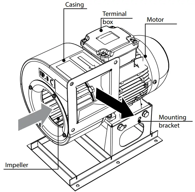
The VCUN fan consists of a metal casing, to which an electric motor and an inlet ring are attached through a flange.
The impeller is attached to the drive shaft.
A bracket for mounting the fan is attached to the bottom of the electric motor. VCUN fans are available in right-hand and left-hand versions.
In the first case, the impeller rotates clockwise and in the second case, the impeller rotates counterclockwise, air intake side view.
MOUNTING AND SET-UP
Having unpacked the fan and prior to installation:
- Carefully read the instructions for installation, start-up, operation and maintenance of the fan.
- Make sure that the fan impeller rotates freely.
- Make sure there is no condensation on the motor.
- Check the electrical resistance of insulation between the motor windings and between each winding and the motor frame.
Follow the safety regulations during the make-ready procedures and fan operation.
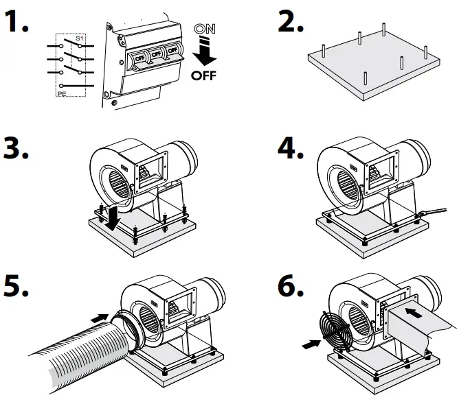
VCUN fan installation sequence:
- Make sure that the fan is disconnected from power mains (Fig. 1).
- Drill holes and fix the bracket using appropriate fasteners (for example, dowels), if necessary, use VVCr or VVCp (optional) antivibration connectors (Fig. 3).
- Ground the fan (Fig. 4).
- Connect the air ducts to the fan.
- On the air supply side, use a FVC-VCU, FVC-VCUN flange (optional) (Fig. 5) or install a RVC VCU, RVC-VCUN protective grille (Fig. 6).

After installing the unit make sure that the fan impeller rotates freely.
CONNECTION TO POWER MAINS
![]() POWER OFF THE POWER SUPPLY PRIOR TO ANY OPERATIONS WITH THE UNIT.
POWER OFF THE POWER SUPPLY PRIOR TO ANY OPERATIONS WITH THE UNIT.
THE UNIT MUST BE CONNECTED TO POWER SUPPLY BY A QUALIFIED ELECTRICIAN.
THE RATED ELECTRICAL PARAMETERS OF THE UNIT ARE GIVEN ON THE MANUFACTURER’S LABEL.
![]() ANY TAMPERING WITH THE INTERNAL CONNECTIONS IS PROHIBITED AND WILL VOID THE WARRANTY.
ANY TAMPERING WITH THE INTERNAL CONNECTIONS IS PROHIBITED AND WILL VOID THE WARRANTY.
The VCUN fan is designed for connection to power mains with the parameters specified in the «Technical data» section.
The connection must be made using durable, insulated and heat-resistant conductors.
When selecting conductors, take into account the maximum permissible wire heating temperature, depending on the type of wire, its insulation, length and method of laying – open, in cable ducts, inside the wall.
The external lead-in must be equipped with an automatic circuit breaker built into the stationary wiring.
The mounting position of the circuit breaker must ensure free access for quick power-off of the unit.
The circuit breaker rated current must correspond to the consumption current of the product (see technical data).
VCUN fan connection sequence:
- Check that there is no voltage on the supply cable.
- Remove the cover from the terminal box located on the motor casing.
- Pull the power supply wires through the cable gland located on the terminal box and strip 7-8 mm of insulation from the ends of the wires.
- Connect the wires to the terminal block, following the wiring diagram and the terminal designations.
- Install the terminal box cover.
Air flow direction must be in compliance with the direction of the arrow on the fan casing.
To check if the rotation direction of the impeller is correct, briefly turn on the fan.
If the rotation direction is not as indicated, switch any two phases at the motor terminals by swapping the corresponding wires on the terminal block in the terminal box.
Connection of the single phase motor 230 V, 50/60 Hz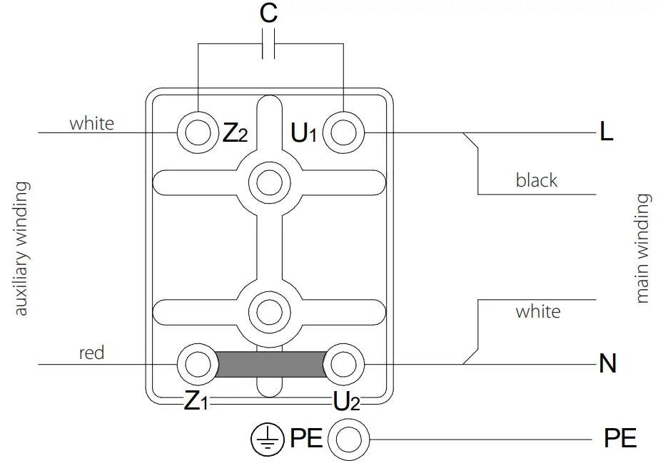
Star connection of a three-phase motor 230/400 V, 50/60 Hz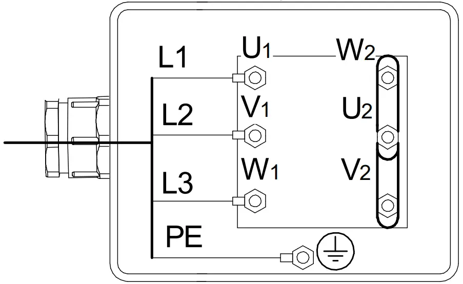
Delta connection of a three-phase motor 400/690 V, 50/60 Hz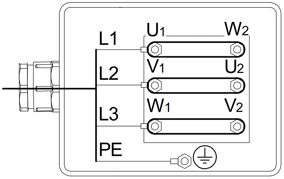
TECHNICAL MAINTENANCE
Prior to performing any technical maintenance and repair disconnect the fan from power mains and wait until its rotating parts come to a complete stop. The technical maintenance includes periodic cleaning of the surfaces from accumulated dust and dirt.
The impeller blades require thorough cleaning once in 6 months.
Connection sequence:
- Cut off power supply to the fan.
- Provide access to the impeller blades.
- For the VCUN fan – unscrew the screws and remove the ring.
- Clean the impeller blades with a dry soft brush or compressed air.
- If the fan is heavily soiled, wet cleaning is recommended.
- To clean the impeller blades, use a soft cloth wetted in a mild detergent solution.
- Avoid liquid dripping on the motor.
Perform all the above operations in the reverse order after cleaning.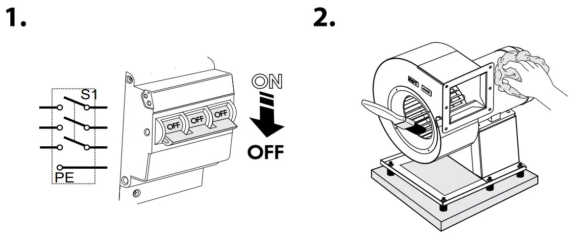
Maintenance checklist
Service the fan regularly to ensure reliable, safe and efficient operation.
General maintenance includes:
- Daily technical maintenance (DTM).
- Technical maintenance (TM-1) after 1000 hours.
- Current repair (CR) after 10 000 hours.
- Overhaul (O) after 20 000 hours. All types of work should be performed according to the schedule, regardless of the technical condition of the fan. A DTM is performed by a locksmith of the 4th or 5th category. A CR and O are performed by a locksmith and an electrician for the repair and operation of equipment.
DTM:
- Check the tightening of the bolts.
- Check the reliability of the grounding.
- Check the absence of unwanted sounds.
TM-1:
- Carry out the DTM operations.
- Eliminate malfunctions of bolted and welded joints.
- Check the clearance between the impeller and the air distribution box.
СR:
- Carry out the TM-1 operations.
- Clean the casing and impeller from dirt.
O:
- Disconnect the air ducts.
- Carry out per-unit disassembly.
- Carry out per-unit assembly from new or repaired parts.
- Check the grease in the bearings, carry out adjustments, tests.
TROUBLESHOOTING
| Problem | Possible reasons | Troubleshooting |
| The fan does not start. | No power supply. | Make sure that the unit is properly connected to the power mains and make any corrections, if necessary. |
| Jammed motor. | Turn off the fan. Troubleshoot the motor jamming. Restart the fan. | |
| Circuit breaker tripping during the fan start. | Excessive electric current consumption caused by a short circuit. | Turn off the fan. Contact the Seller. |
| Noise, vibration. | The fan impeller is soiled. | Clean the impellers. |
| The screw connection is loose. | Check the screw connection and tighten the screws if needed. | |
| Resonance with the mounting structure. | Use VVCr and VVCp vibration dampers recommended for your fan model. |
STORAGE AND TRANSPORTATION REGULATIONS
- Store the unit in the manufacturer’s original packaging box in a dry closed ventilated premise with temperature range from +5 °C to + 40 °C and relative humidity up to 70 %.
- Storage environment must not contain aggressive vapors and chemical mixtures provoking corrosion, insulation, and sealing deformation.
- Use suitable hoist machinery for handling and storage operations to prevent possible damage to the unit.
- Follow the handling requirements applicable for the particular type of cargo.
- The unit can be carried in the original packaging by any mode of transport provided proper protection against precipitation and mechanical damage. The unit must be transported only in the working position.
- Avoid sharp blows, scratches, or rough handling during loading and unloading.
- Prior to the initial power-up after transportation at low temperatures, allow the unit to warm up at operating temperature for at least 3-4 hours.
MANUFACTURER’S WARRANTY
The product is in compliance with EU norms and standards on low voltage guidelines and electromagnetic compatibility. We hereby declare that the product complies with the provisions of Electromagnetic Compatibility (EMC) Directive 2014/30/EU of the European Parliament and of the Council, Low Voltage Directive (LVD) 2014/35/EU of the European Parliament and of the Council and CE-marking Council Directive 93/68/EEC. This certificate is issued following test carried out on samples of the product referred to above.
The manufacturer hereby warrants normal operation of the unit for 24 months after the retail sale date provided the user’s observance of the transportation, storage, installation, and operation regulations. Should any malfunctions occur in the course of the unit operation through the Manufacturer’s fault during the guaranteed period of operation, the user is entitled to get all the faults eliminated by the manufacturer by means of warranty repair at the factory free of charge. The warranty repair includes work specific to elimination of faults in the unit operation to ensure its intended use by the user within the guaranteed period of operation. The faults are eliminated by means of replacement or repair of the unit components or a specific part of such unit component.
The warranty repair does not include:
- routine technical maintenance
- unit installation/dismantling
- unit setup
To benefit from warranty repair, the user must provide the unit, the user’s manual with the purchase date stamp, and the payment paperwork certifying the purchase. The unit model must comply with the one stated in the user’s manual. Contact the Seller for warranty service.
The manufacturer’s warranty does not apply to the following cases:
- User’s failure to submit the unit with the entire delivery package as stated in the user’s manual including submission with missing component parts previously dismounted by the user.
- Mismatch of the unit model and the brand name with the information stated on the unit packaging and in the user’s manual.
- User’s failure to ensure timely technical maintenance of the unit.
- External damage to the unit casing (excluding external modifications as required for installation) and internal components caused by the user.
- Redesign or engineering changes to the unit.
- Replacement and use of any assemblies, parts and components not approved by the manufacturer.
- Unit misuse.
- Violation of the unit installation regulations by the user.
- Violation of the unit control regulations by the user.
- Unit connection to power mains with a voltage different from the one stated in the user’s manual.
- Unit breakdown due to voltage surges in power mains.
- Discretionary repair of the unit by the user.
- Unit repair by any persons without the manufacturer’s authorization.
- Expiration of the unit warranty period.
- Violation of the unit transportation regulations by the user.
- Violation of the unit storage regulations by the user.
- Wrongful actions against the unit committed by third parties.
- Unit breakdown due to circumstances of insuperable force (fire, flood, earthquake, war, hostilities of any kind, blockades).
- Missing seals if provided by the user’s manual.
- Failure to submit the user’s manual with the unit purchase date stamp.
- Missing payment paperwork certifying the unit purchase.
![]() FOLLOWING THE REGULATIONS STIPULATED HEREIN WILL ENSURE A LONG AND TROUBLE-FREE OPERATION OF THE UNIT.
FOLLOWING THE REGULATIONS STIPULATED HEREIN WILL ENSURE A LONG AND TROUBLE-FREE OPERATION OF THE UNIT.
![]() USER’S WARRANTY CLAIMS SHALL BE SUBJECT TO REVIEW ONLY UPON PRESENTATION OF THE UNIT, THE PAYMENT DOCUMENT AND THE USER’S MANUAL WITH THE PURCHASE DATE STAMP.
USER’S WARRANTY CLAIMS SHALL BE SUBJECT TO REVIEW ONLY UPON PRESENTATION OF THE UNIT, THE PAYMENT DOCUMENT AND THE USER’S MANUAL WITH THE PURCHASE DATE STAMP.
CERTIFICATE OF ACCEPTANCE
| Unit Type | Centrifugal fan in a scroll casing |
| Model | VCUN |
| Serial Number | |
| Manufacture Date | |
| Quality Inspector’s Stamp |
SELLER INFORMATION
| Seller | |
| Address | |
| Phone Number | |
| Purchase Date | |
| This is to certify acceptance of the complete unit delivery with the user’s manual. The warranty terms are acknowledged and accepted. | |
| Customer’s Signature | |
Seller’s Stamp
INSTALLATION CERTIFICATE
| The VCUN unit is installed pursuant to the requirements stated in the present user’s manual. | ||
| Company name | ||
| Address | ||
| Phone Number | ||
| Installation Technician’s Full Name | ||
| Installation Date: | Signature: | |
| The unit has been installed in accordance with the provisions of all the applicable local and national construction, electrical and technical codes and standards. The unit operates normally as intended by the manufacturer. | ||
| Signature: | ||
Installation Stamp
WARRANTY CARD
| Unit Type | Centrifugal fan in a scroll casing |
| Model | VCUN |
| Serial Number | |
| Manufacture Date | |
| Purchase Date | |
| Warranty Period | |
| Seller |
Seller’s Stamp
Scan QR code