![]()
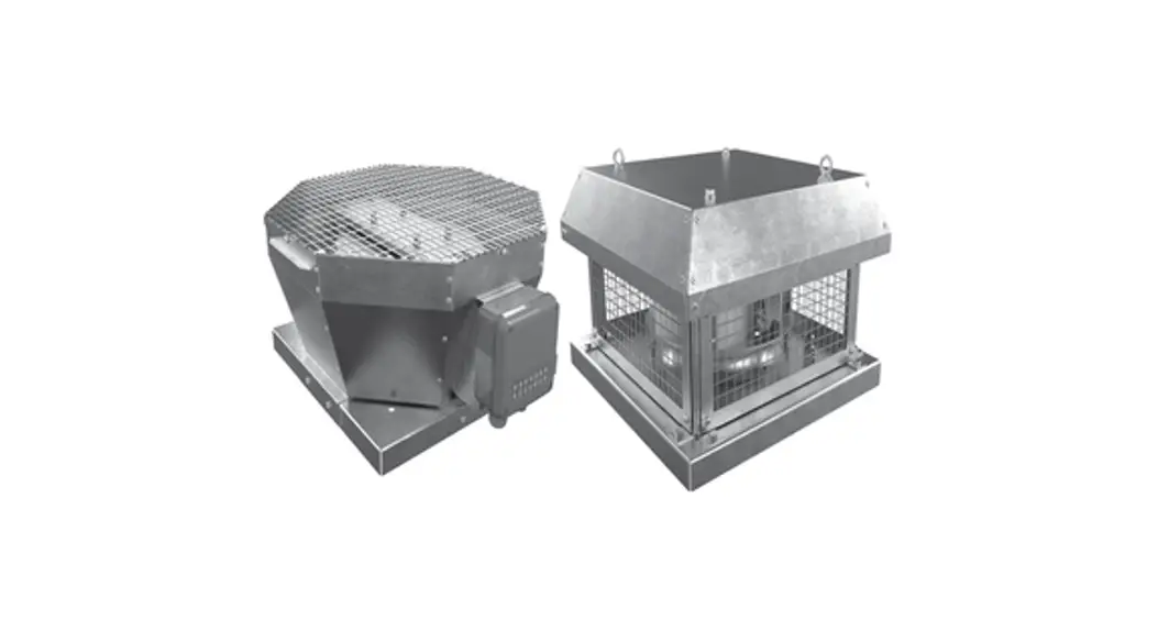
VKV Centrifugal Roof Fan
User Manual
VKV Centrifugal Roof Fan
Centrifugal roof fan
This user manual is a main operating document intended for technical, maintenance, and operating staff.
The manual contains information about the purpose, technical details, operating principle, design, and installation of the VKV/VKH unit and all its modifications.
Technical and maintenance staff must have theoretical and practical training in the field of ventilation systems and should be able to work in accordance with workplace safety rules as well as construction norms and standards applicable in the territory of the country.
SAFETY REQUIREMENTS
All user’s manual requirements as well as the provisions of all the applicable local and national construction, electrical, and technical norms and standards must be observed when installing and operating the unit.
Disconnect the unit from the power supply prior to any connection, servicing, maintenance, and repair operations.
Only qualified electricians with a work permit for electrical units up to 1000 V are allowed for installation. The present user’s manual should be carefully read before beginning work.
Check the unit for any visible damage to the impeller, the casing, and the grille before starting installation. The casing internals must be free of any foreign objects that can damage the impeller blades.
While mounting the unit, avoid compression of the casing! Deformation of the casing may result in motor jams and excessive noise.
Misuse of the unit and any unauthorized modifications are not allowed. Transported air must not contain any dust or other solid impurities, sticky substances, or fibrous
materials.
Do not use the unit in a hazardous or explosive environment containing spirits, gasoline, insecticides, etc.
Do not close or block the intake or extract vents in order to ensure efficient airflow.
Do not sit on the unit and do not put objects on it.
The information in this user’s manual was correct at the time of the document’s preparation. The Company reserves the right to modify the technical characteristics, design, or configuration of its products at any time in order to incorporate the latest technological developments. Never touch the unit with wet or damp hands. Never touch the unit when barefoot.
This unit is not intended for use by persons (including children) with reduced physical, sensory or mental capabilities, or lack of experience and knowledge unless they have een given supervision or instruction concerning use of the unit by a person responsible for their safety. Children should be supervised to ensure that they do not play with the unit.
This appliance can be used by children aged 8 years and above and persons with reduced physical, sensory or mental capabilities or lack of experience and knowledge if they have been given supervision or instruction concerning the use of the appliance in a safe way and understand the hazards involved Cleaning and user maintenance shall not be made by children without supervision Children shall not play with the appliance.
Connection to the mains must be made through a disconnecting device, which is integrated into the fixed wiring system in accordance with the wiring rules for the design of electrical units and has a contact separation in all poles that allows for full disconnection under overvoltage category III conditions.
If the supply cord is damaged, it must be replaced by the manufacturer, its service agent, or similarly qualified persons in order to avoid a safety hazard.
Ensure that the unit is switched off from the supply mains before removing the guard.
WARNING: If there are any unusual oscillating movements, immediately stop using the unit and contact the manufacturer, its service agent, or suitably qualified persons.
The replacement of parts of the safety suspension system device shall be performed by the manufacturer, its service agent, or suitably qualified persons.
Precautions must be taken to avoid the back-flow of gases into the room from the open flue of gas or other fuel-burning appliances.
The manufacturer, designer, installer, and operator are responsible for the correct operation and functioning of the unit.![]() THE PRODUCT MUST BE DISPOSED OF SEPARATELY AT THE END OF ITS SERVICE LIFE. DO NOT DISPOSE OF THE UNIT AS UNSORTED DOMESTIC WASTE
THE PRODUCT MUST BE DISPOSED OF SEPARATELY AT THE END OF ITS SERVICE LIFE. DO NOT DISPOSE OF THE UNIT AS UNSORTED DOMESTIC WASTE THE UNIT SHOULD NOT BE OPERATED BY CHILDREN OR PERSONS WITH REDUCED PHYSICAL, MENTAL, OR SENSORY CAPACITIES, OR THOSE WITHOUT THE APPROPRIATE TRAINING.
THE UNIT MUST BE INSTALLED AND CONNECTED ONLY BY PROPERLY QUALIFIED PERSONNEL AFTER THE APPROPRIATE BRIEFING.
THE CHOICE OF UNIT INSTALLATION LOCATION MUST PREVENT UNAUTHORISED ACCESS BY UNATTENDED CHILDREN.
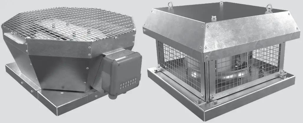
The VKV/VKH roof fans in the metal casing are designed for ventilation systems in industrial premises as well as pools, apartment buildings, offices, hospitals, restaurants, and other premises heated during the winter season. The fan is mounted on the exhaust shaft of the air duct and is used only for exhaust ventilation.
DELIVERY SET
| NAME | NUMBER |
| Fan | 1 pc. |
| User’s manual | 1 pc. |
| Packing box | 1 pc. |
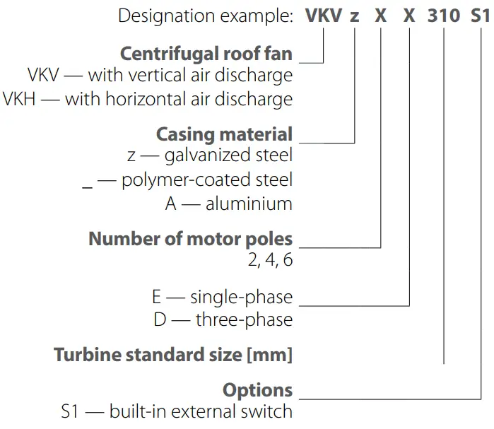
DESIGNATION KEY
TECHNICAL DATA
The unit is rated as a Class I electrical appliance.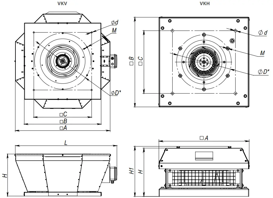
D* – flange connection dimensions.
| Model | Overall and connecting dimensions [mm] | weight [kg] | |||||||
| H [mm] | A [mm] | B [mm] | C [mm] | D [mm] | d [mm] (4 holes) | M [mm] (6 places) | L [mm] | ||
| VKV 2E 190 | 170 | 417 | 355 | 245 | 213 | 9 | M6 | 480 | 7 |
| VAN 2E 220 | 190 | 417 | 355 | 245 | 213 | 9 | M6 | 480 | 7 |
| VAN 2E 225 | 215 | 417 | 355 | 245 | 210 | 9 | M6 | 480 | 7 |
| VIC/ 4E 225 | 215 | 417 | 355 | 245 | 210 | 9 | M6 | 480 | 7 |
| VIC/ 2E 250 | 240 | 481 | 425 | 330 | 285 | 11 | M6 | 540 | 9 |
| VKV 4E 250 | 240 | 481 | 425 | 330 | 285 | 11 | M6 | 540 | 9 |
| VKV 4E 280 | 276 | 547 | 425 | 330 | 291 | 11 | M6 | 600 | 13 |
| VIN 2E 310 | 276 | 547 | 425 | 330 | 285 | 11 | M6 | 600 | 13 |
| VKV4E 310 | 300 | 613 | 477 | 330 | 285 | 11 | M6 | 670 | 20 |
| VKV 4D 310 | 300 | 613 | 477 | 750 | 285 | 11 | M6 | 670 | 19 |
| VKV 4E 355 | 330 | 738 | 598 | 450 | 438 | 11 | M8 | 790 | 26 |
| VKV 4D 355 | 330 | 738 | 598 | 450 | 438 | 11 | M8 | 790 | 26 |
| VKV 4E 400 | 375 | 738 | 598 | 450 | 438 | 11 | M8 | 790 | 33 |
| VKV 6E 400 | 375 | 738 | 598 | 450 | 438 | 11 | M8 | 790 | 31 |
| VKV 4D 400 | 375 | 738 | 598 | 450 | 438 | 11 | M8 | 790 | 33 |
| VKV 4E 450 | 430 | 738 | 668 | 535 | 438 | 11 | M8 | 790 | 41 |
| VKV 6E 450 | 430 | 738 | 668 | 535 | 438 | 11 | M8 | 790 | 41 |
| VKV 4D 450 | 425 | 738 | 668 | 535 | 438 | 11 | M8 | 790 | 41 |
| VKV 6E 500 | 460 | 859 | 668 | 535 | 445 | 11 | M8 | 910 | 52 |
| VKV 4D 500 | 460 | 859 | 668 | 535 | 430 | 11 | M8 | 910 | 52 |
| VKV 6D 500 | 460 | 859 | 668 | 535 | 445 | 11 | M8 | 910 | 52 |
| VKV 6E 560 | 485 | 859 | 833 | 750 | 605 | 11 | M8 | 910 | 63 |
| VKV 4D 560 | 485 | 859 | 833 | 750 | 605 | 11 | M8 | 910 | 63 |
| VKV 6D 560 | 485 | 859 | 833 | 750 | 605 | 11 | M8 | 910 | 63 |
| VKV 6D 630 | 485 | 951 | 939 | 750 | 600 | 20 | M8 | 1000 | 81 |
| VKV 6D 710 | 485 | 992 | 980 | 840 | 674 | 20 | M8 | 1040 | 114 |
| Model | Overall and connecting dimensions [mm] | Weight [kg] | |||||||
| H [mm] | H1 [mm] | A [mm] | B [mm] | C [mm] | D [mm] | d [mm] (4 holes) | M [mm] (6 places) | ||
| VKH 2E 190 | 189 | 195 | 351 | 350 | 245 | 213 | 11 | M6 | 8.2 |
| VKH 2E 220 | 180 | 186 | 337 | 338 | 245 | 213 | 11 | M6 | 7 |
| VKH 2E 225 | 210 | 217 | 351 | 350 | 245 | 210 | 11 | M6 | 9.2 |
| VKH 4E 225 | 233 | 240 | 351 | 350 | 245 | 210 | 11 | M6 | 8.8 |
| VKH 2E 250 | 237 | 244 | 451 | 450 | 330 | 285 | 11 | M6 | 12.7 |
| VKH 4E 250 | 237 | 244 | 451 | 450 | 330 | 285 | 11 | M6 | 12.1 |
| VKH 4E 280 | 265 | 272 | 451 | 450 | 330 | 291 | 11 | M6 | 13.5 |
| VKH 2E 310 | 251 | 258 | 451 | 450 | 330 | 291 | 11 | M6 | 13.2 |
| VKH 4E 310 | 287 | 294 | 451 | 450 | 330 | 285 | 11 | M6 | 14.2 |
| VKH 4D 310 | 287 | 294 | 451 | 450 | 330 | 285 | 11 | M6 | 14.2 |
| VKH 4E 355 | 322 | 361 | 625 | 620 | 450 | 438 | 11 | M8 | 28.3 |
| VKH 4D 355 | 347 | 386 | 625 | 620 | 450 | 438 | 11 | M8 | 30.3 |
| VKH 4E 400 | 376 | 415 | 625 | 620 | 450 | 438 | 11 | M8 | 35 |
| VKH 6E 400 | 376 | 415 | 625 | 620 | 450 | 438 | 11 | M8 | 32.7 |
| VKH 4D 400 | 376 | 415 | 625 | 620 | 450 | 438 | 11 | M8 | 35 |
| VKH 4E 450 | 420 | 459 | 710 | 700 | 535 | 438 | 11 | M8 | 46.6 |
| VKH 6E 450 | 420 | 459 | 710 | 700 | 535 | 438 | 11 | M8 | 45.6 |
| VKH 4D 450 | 420 | 459 | 710 | 700 | 535 | 438 | 11 | M8 | 45.5 |
| VKH 6E 500 | 461 | 501 | 710 | 700 | 535 | 445 | 11 | M8 | 52.8 |
| VKH 4D 500 | 490 | 530 | 710 | 700 | 535 | 430 | 11 | M8 | 46.6 |
| VKH 6D 500 | 461 | 501 | 710 | 700 | 535 | 445 | 11 | M8 | 52.7 |
| VKH 6E 560 | 489 | 528 | 900 | 895 | 750 | 605 | 11 | M8 | 76.4 |
| VKH 4D 560 | 489 | 528 | 900 | 895 | 750 | 605 | 11 | M8 | 814 |
| VKH 6D 560 | 489 | 528 | 900 | 895 | 750 | 605 | 11 | M8 | 76.4 |
| VKH 6D 630 | 520 | 560 | 1000 | 990 | 750 | 600 | 20 | M8 | 96.3 |
| VKH 6D 710 | 570 | 619 | 1060 | 1050 | 840 | 674 | 20 | M8 | 134 |
| VKVNKH 2E 190 | VKVNKH 2E 220 | VKVNKH 2E 225 | VINA41-1 4E 225 | VKVNKH 2E 250 | MWM<H 4E 250 | |||||
| Voltage [V] | 1— 230 | 1— 230 | 1— 230 | 1— 230 | 1— 230 | 1— 230 | ||||
| Frequency [Hz] | 50 | 60 | 50 | 60 | 50 | 60 | 50 | 50 | 60 | 50 |
| Power [W] | 69 | 89 | 108 | 118 | 123 | 169 | 49 | 184 | 232 | 48 |
| Current [A] | 0.30 | 0.40 | 0.49 | 0.54 | 0.54 | 0.70 | 0.22 | 0.81 | 0.90 | 0.23 |
| Max. airflow [m3/h] | 610 | 654 | 880 | 883 | 915 | 1010 | 738 | 1450 | 1320 | 820 |
| RPM [min-1] | 2680 | 2980 | 2580 | 2840 | 2790 | 2820 | 1400 | 2480 | 2320 | 1440 |
| Sound pressure level at 3 m distance [dBA] | 48 | 49 | 50 | 51 | 51 | 52 | 45 | 54 | 53 | 46 |
| Transported air temperature [°C] | -25.. +50 | |||||||||
| SEC class* | C | – | C | – | C | – | C | – | – | – |
| Ingress protection rating | IPX4 | |||||||||
| VKVNKH 4E 280 | VKVNKH 2E 310 | VKVNKH 4E 310 | VKVNKH 4D 310 | VKVNKH 4E 355 | VKVNKH 4D 355 | ||||||
| Voltage [V] | 1— 230 | 1— 230 | 1— 230 | 3— 400 | 1— 230 | 3— 400 | |||||
| Frequency [Hz] | 50 | 60 | 50 | 50 | 60 | 50 | 60 | 50 | 60 | 50 | 60 |
| Power [W] | 125 | 155 | 324 | 141 | 195 | 155 | 202 | 219 | 304 | 264 | 330 |
| Current [A] | 0.61 | 0.99 | 1.42 | 0.64 | 0.87 | 0.29 | 0.32 | 0.96 | 1.33 | 0.58 | 0.64 |
| Max. airflow [rn3/h] | 1490 | 1520 | 2150 | 2265 | 2425 | 2300 | 2442 | 2480 | 2976 | 3290 | 3540 |
| RPM [min1] | 1446 | 1710 | 2620 | 1420 | 1740 | 1410 | 1550 | 1420 | 1580 | 1430 | 1650 |
| Sound pressure level at 3 m distance [dBA] | 46 | 46 | 58 | 47 | 49 | 47 | 48 | 51 | 52 | 52 | 53 |
| Transported air temperature [°C] | -25…+50 | -30.. +60 | |||||||||
| Ingress protection rating | IPX4 | ||||||||||
| VKVNKH 4E 400 | VKVNKH 6E 400 | VKVNKH 4D 400 | VKVNKH 4E 450 | VKVNKH 6E 450 | VKVNKH 4D 450 | VKVNKH 4D 500 | ||
| Voltage [V] | 1— 230 | 1— 230 | 3-400 | 1— 230 | 1— 230 | 3-400 | 3400 | |
| Frequency [Hz] | 50 | 50 | 60 | 50 | 50 | 50 | 50 | 50 |
| Power [W] | 457 | 184 | 249 | 420 | 749 | 268 | 755 | 1527 |
| Current [A] | 2.00 | 0.89 | 1.10 | 0.99 | 3.35 | 1.25 | 1.50 | 2.64 |
| Max. airflow [m3/h] | 3950 | 2740 | 3289 | 3950 | 6180 | 4380 | 5920 | 8435 |
| RPM [min-1] | 1440 | 945 | 1071 | 1440 | 1400 | 940 | 1440 | 1460 |
| Sound pressure level at 3 m distance [dBA] | 55 | 47 | 49 | 55 | 58 | 50 | 57 | 62 |
| Transported air temperature [°C] | -30…+60 | -30…+50 | ||||||
| Ingress protection rating | IPX4 | |||||||
| VKVNKH 6E 500 | VKVNKH 6D 500 | VKVNKH 4D 560 | VKVNKH 6E 560 | VKVNKH 6D 560 | VKVNKH 6D 630 | VKVNKH 6D 710 | |||
| Voltage [V] | 1230 | 3-400 | 3-400 | 1-230 | 3-400 | 3-400 | 3-400 | ||
| Frequency [Hz] | 50 | 60 | 50 | 60 | 50 | 50 | 50 | 50 | 50 |
| Power [W] | 407 | 673 | 440 | 599 | 1970 | 613 | 696 | 1110 | 2583 |
| Current [A] | 1.81 | 3.05 | 1.23 | 1.32 | 3.36 | 2.70 | 1.44 | 2.42 | 4.87 |
| Max. airflow [m3/hl | 5680 | 6532 | 6000 | 6122 | 13560 | 9560 | 9630 | 12640 | 17010 |
| RPM [min-1] | 970 | 1120 | 978 | 1125 | 1400 | 930 | 970 | 957 | 945 |
| Sound pressure level at 3 m distance [dBA] | 52 | 54 | 52 | 54 | 66 | 58 | 58 | 64 | 67 |
| Transported air temperature [°C] | -25.. +60 | -25 ..+50 | -25…+70 | ||||||
| Ingress protection rating | IPX4 | ||||||||
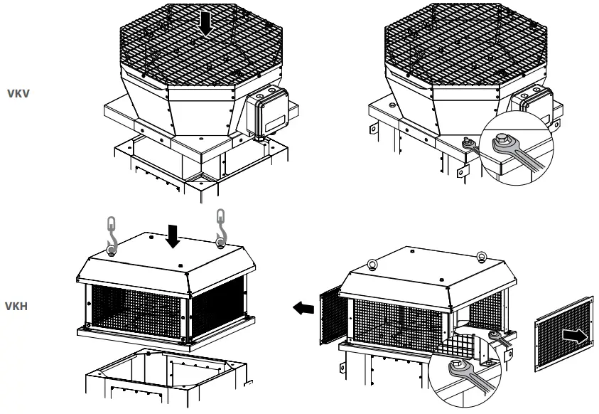
![]() BEFORE MOUNTING MAKE SURE THE CASING DOES NOT CONTAIN ANY FOREIGN OBJECTS (E.G. FOIL, PAPER).
BEFORE MOUNTING MAKE SURE THE CASING DOES NOT CONTAIN ANY FOREIGN OBJECTS (E.G. FOIL, PAPER).![]() WHILE INSTALLING THE UNIT ENSURE CONVENIENT ACCESS FOR SUBSEQUENT MAINTENANCE AND REPAIR.
WHILE INSTALLING THE UNIT ENSURE CONVENIENT ACCESS FOR SUBSEQUENT MAINTENANCE AND REPAIR.
- Fans are designed for horizontal mounting on a flat roof directly above an air duct or a ventilation shaft.
- In order to avoid the ingress of water and snow into the ventilation duct, it is possible to install a fan on the mounting frame.
- The fan is connected to the ventilation duct by means of a counter flange, which is attached directly to the fan base.
- The fan base has holes for fixing bolts that attach the fan to a stationary even surface or to a mounting frame.
- In the VKV 2E 200, VKV 2E 225, VKV 4E 225, VKV 4E 310, VKV 4D 310, VKV/VKH 6E 500, VKV/VKH 4D 500, VKV/VKH 6D 500, VKV/juVKH 6D 630, VKV/VKH 6D 710 models the counter flange is attached together with the fan inlet ring.
- A mounting frame, a counter flange, and mounting bolts are not included in the delivery set and must be purchased separately.
![]() OPERATION OF FANS WITHOUT A CONNECTED AIR DUCT SYSTEM IS IMPROPER
OPERATION OF FANS WITHOUT A CONNECTED AIR DUCT SYSTEM IS IMPROPER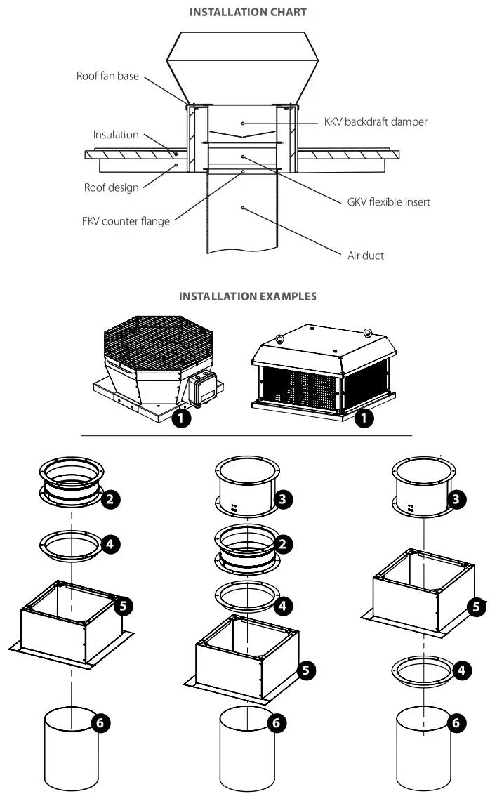
1 – roof fan; 2 – GVK flexible insert; 3 – KKV backdraft damper; 4 – FKV counter flange; 5 – RKV or RKVI mounting frame; 6 – air duct.
CONNECTION TO POWER MAINS
![]() DISCONNECT THE POWER SUPPLY PRIOR TO ANY OPERATIONS WITH THE UNIT. CONNECTION OF THE UNIT TO POWER MAINS IS ALLOWED BY A QUALIFIED ELECTRICIAN WITH A WORK PERMIT FOR THE ELECTRIC UNITS UP TO 1000 V AFTER CAREFUL READING OF THE PRESENT USER’S MANUAL. THE RATED ELECTRICAL PARAMETERS OF THE UNIT ARE GIVEN ON THE MANUFACTURER’S LABEL.
DISCONNECT THE POWER SUPPLY PRIOR TO ANY OPERATIONS WITH THE UNIT. CONNECTION OF THE UNIT TO POWER MAINS IS ALLOWED BY A QUALIFIED ELECTRICIAN WITH A WORK PERMIT FOR THE ELECTRIC UNITS UP TO 1000 V AFTER CAREFUL READING OF THE PRESENT USER’S MANUAL. THE RATED ELECTRICAL PARAMETERS OF THE UNIT ARE GIVEN ON THE MANUFACTURER’S LABEL.![]() ANY TAMPERING WITH THE INTERNAL CONNECTIONS IS PROHIBITED AND WILL VOID THE WARRANTY.
ANY TAMPERING WITH THE INTERNAL CONNECTIONS IS PROHIBITED AND WILL VOID THE WARRANTY.
- The unit is rated for connection to power mains with the parameters specified in the “Technical data” section, according to the wiring diagram.
- The connection must be made using insulated conductors (cables, wires). The actual wire cross-section selection must be based on the maximum load current, and maximum conductor temperature depending on the wire type, insulation, length, and installation method.
- The unit should be connected to the fixed wiring system in compliance with current regulations. Connection to power mains should be made inside the terminal box located on the fan casing, according to the wiring diagram and terminal designation. The terminal designations are shown on the label inside the terminal box. Fan electrical data is shown on the label on the fan casing.
Depending on the modification, the fan motors can have no built-in thermal protection. This should be taken into account when choosing a motor starter or a contractor.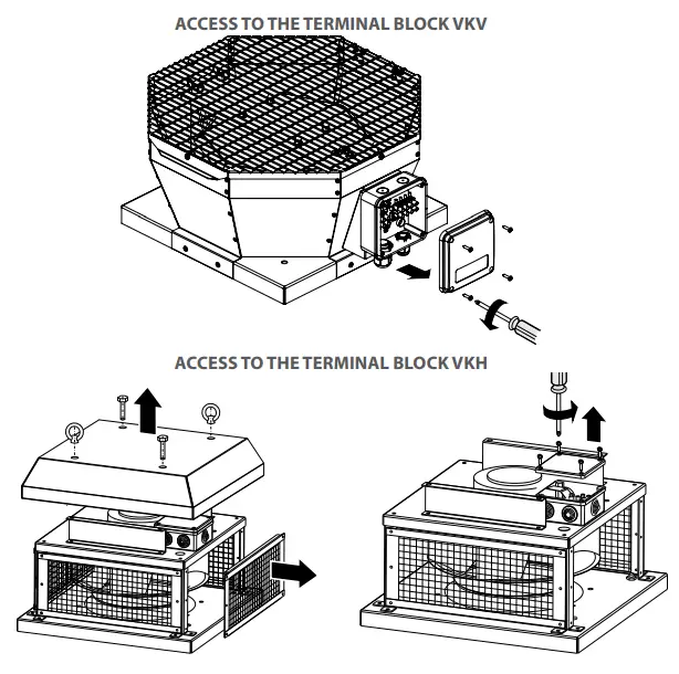
Power supply parameters and examples of wiring diagrams depending on the unit model
Wiring diagram 1: VKV/VKH 2E 190, VKV/VKH 2E 220, VKV/VKH 2E 225, VKV/VKH 4E 225, VKV/VKH 2E 250, VKV/VKH 4E 250, VKV/VKH 4E 280,
VKV/VKH 2E 310, VKV/VKH 4E 310, VKV/VKH 4E 355, VKV/VKH 4E 400, VKV/VKH 6E 400, VKV/VKH 4E 450, VKV/VKH 6E 450 Depending on the modification, the fans can have thermal contacts. Then it is necessary to use wiring diagram 5 instead of wiring
diagram 1.
Wiring diagram 2: VKV/VKH 4D 355.
Wiring diagram 3: VKV/VKH 4D 310, VKV/VKH 4D 400, VKV/VKH 4D 450, VKV/VKH 4D 500, VKV/VKH 4D 560.
Wiring diagram 4: VKV/VKH 6D 710.
Wiring diagram 5: VKV/VKH 6E 500, VKV/VKH 6E 560.
Wiring diagram 6: VKV/VKH 6D 500, VKV/VKH 6D 560, VKV/VKH 6D 630.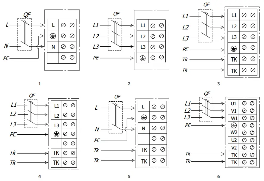
WIRING DIAGRAM DESIGNATIONS:
L(x): phase; N: neutral; QF: automatic circuit breaker; PE: protective ground wire; TK: motor thermal protection contacts.
| Model | Recommended rated current of the automatic circuit breaker [A] | Recommended cable, nxt, where n is the number of wires, and S is the cross-section in mm2 |
| VKVNKH 2E 190…250 VKVNKH 4E 310 | 1 | 3×0.5 |
| VKVNKH 4E 355 | 1.6 | 3×0.5 |
| VKVNKH 4E 400…450 | 4 | 3×1.0 |
| VKVNKH 6E 500…560 | 2.5 | 3×1.0 |
| VKVNKH 4D 310…450 | 1 | 5×0.5 |
| VKVNKH 6D 500…710 EC | 10 | 5×1.5 |
ASYNCHRONOUS ELECTRIC MOTOR STARTING METHODS
There are several methods for starting asynchronous squirrel-cage electric motors. The most common methods are direct-on-line (DOL), with a soft starter (SS), or with a frequency converter (FC).
Direct-on-line starting
In the case of direct-on-line starting (i.e. by connecting the motor to the electric mains with a simple line contactor), the motor starting time significantly increases due to the high inertia of the impeller, which, in turn, results in high in-rush starting currents in the circuit. These currents of long duration may cause voltage slumps (especially if the feed line section falls short of the requirements), which may affect load operation. The in-rush current consumed by an electric motor in case of DOL starting is 5-8 times larger than the rated value (or even 10-14 times larger in some rare instances). It should be noted that the torque developed by the motor also significantly exceeds the rated value. Upon energization, the motor operates as a transformer with a squirrel-cage secondary winding formed by the rotor cage with very low resistance. The rotor develops high induced current causing a rush of current in the feed line. The startup torque during starting averages 0.5-1.5 of the rated torque value. Despite such advantages as simple construction, high startup current, quick start, and low cost, direct-on-line systems are suitable only in the following cases:
- the motor power is low compared to the mains power which limits the adverse effect of the rush of current
- the driven mechanism does not require gradual speed build-up or is equipped with a damping device to smooth out the inrush
- the high startup torque has no adverse effects on the operation of the driven mechanism
Soft start. SS starting.
A soft starter gradually increases the voltage supplied to the motor – from the initial to the rated value.
This starting system can be used to meet the following goals:
- limit the motor current
- regulate the torque
Regulation by limiting the current sets the maximum in-rush current equal to 300-400 % (or 250 % in some rare instances) of the rated current and reduces torque characteristics. This type of regulation is especially suited for turbomachinery such as centrifugal pumps and fans. Regulation by variation of torque optimizes the torque during startup and reduces the in-rush current in the circuit. These conditions are suitable for mechanisms with the constant load resistance. This type of soft starting may differ in the implementation pattern:
- motor start
- motor start and stop
- device bridging at the end of the start sequence
- tart and stop of several motors in stage circuits
Soft start. FC starting.
During the starting, the FC raises the frequency from 0 Hz to the electrical mains frequency (50 or 60 Hz). As the frequency is increased gradually, the motor can be assumed to operate at its rated speed for a given frequency value. Furthermore, on the assumption that the motor runs at its rated speed, the nominal torque should be immediately available whereas the current will be approximately equal to the rated value.
This starting system is used for speed control and regulation and can be used in the following cases:
- start with a high-inertia load
- start with a high load and limited-capacity power supply source
- optimization of electric power consumption depending on turbomachinery speed
The aforementioned starting system can be used for all types of mechanisms.
MAKE SURE THAT THE FAN IMPELLER ROTATES IN THE DIRECTION MARKED BY THE ARROW ON THE FAN CASING.![]() IF NECESSARY, CHANGE THE IMPELLER ROTATION DIRECTION BY ALTERING THE PHASE SEQUENCE ON THE ELECTRIC MOTOR TERMINALS.
IF NECESSARY, CHANGE THE IMPELLER ROTATION DIRECTION BY ALTERING THE PHASE SEQUENCE ON THE ELECTRIC MOTOR TERMINALS.
Problems associated with DOL starting
The problems caused by DOL starting may be divided into two groups:
- An abrupt start causes mechanical shock, jolts in the mechanism, shock removal of free play, etc.
- A heavy start cannot be completed.
Let us review three variations of a heavy start:
- The feed line performance is barely sufficient or insufficient to maintain the induced current.
Typical symptoms: Upon starting the circuit breakers at the system input are tripped; the lights, certain relays, and contactors go off, and the supply generator shuts down.
Solution: In the best-case scenario an SS device may help reduce the in-rush current to 250 % of the motor-rated current. If this is insufficient, an FC is necessary. - The motor cannot start the mechanism with DOL starting.
Typical symptoms: The motor fails to turn or “freezes” at a certain speed which is maintained until the actuation of the protection suite.
Solution: This problem may not be solved with an SS device. The motor develops insufficient shaft torque. However, this problem can be addressed by using an FC, but each case may be different. - The motor spins up the mechanism with authority but fails to reach the rated rotation speed.
Typical symptoms: The input automatic circuit breaker is tripped during spin-up. This often happens with heavy-weight fans with a considerable rotation speed.
Solution: Such problems may be addressed with an SS device, but not with 100 % certainty. The closer the motor speed to the rated value during the actuation of the protective equipment, the higher the chances of success. The use of an FC in this case helps solve the problem fundamentally.
Standard switching equipment (automatic circuit breakers, contactors, and motor starters) is not designed to withstand prolonged overloads normally causing the fan to shut down automatically DOL starting that continues for a long period of time.
Using switching equipment with a higher maximum current rating renders the electric motor protection system less sensitive. As a result, the switching equipment will not be able to detect motor overload in time due to a high current sensing threshold. Such problems as mentioned above can only be addressed by utilizing a soft starter or a frequency converter to start the fan.![]() THE ORGANISATION RESPONSIBLE FOR THE COMMISSIONING SHALL BE RESPONSIBLE FOR PROPER MOTOR PHASING AND STARTING PATTERN SELECTION.
THE ORGANISATION RESPONSIBLE FOR THE COMMISSIONING SHALL BE RESPONSIBLE FOR PROPER MOTOR PHASING AND STARTING PATTERN SELECTION.![]() DURING STARTING THE IN-RUSH CURRENTS OF THE FAN MAY SEVERAL TIMES EXCEED THE RATED VALUES.
DURING STARTING THE IN-RUSH CURRENTS OF THE FAN MAY SEVERAL TIMES EXCEED THE RATED VALUES.
SEE “ASYNCHRONOUS ELECTRIC MOTOR STARTING METHODS” IN THE “CONNECTION TO POWER MAINS” SECTION
- After fan starting make sure that the electric motor rotates properly without undue vibration and abnormal noise.
- Make sure that the fan impeller rotates in the direction marked by the arrow on the fan casing. If necessary, change the rotation direction of the impeller by reversing the phase sequence (for a three-phase motor) or by rewiring according to the wiring diagram located inside the terminal box (for a single-phase motor).
- Make sure that the fan energy consumption complies with the value given on the equipment nameplate and check the motor for overheating.
- The phase current should be checked once the fan reaches the rated operating conditions.
- Do not switch the fan on and off several times without pauses as this may result in damage to the winding or insulation due to overheating.
In conditions of low temperatures and high humidity, in order to avoid freezing or water ingress into the duct, the unit must be operated continuously.
TECHNICAL MAINTENANCE
![]() DISCONNECT THE UNIT FROM THE POWER SUPPLY BEFORE ANY MAINTENANCE OPERATIONS!
DISCONNECT THE UNIT FROM THE POWER SUPPLY BEFORE ANY MAINTENANCE OPERATIONS!
MAKE SURE THE UNIT IS DISCONNECTED FROM POWER MAINS BEFORE REMOVING THE PROTECTION![]() PRIOR TO COMMENCING ANY TECHNICAL MAINTENANCE PUT UP A PROHIBITORY SIGN ON THE FAN STARTING PANEL:
PRIOR TO COMMENCING ANY TECHNICAL MAINTENANCE PUT UP A PROHIBITORY SIGN ON THE FAN STARTING PANEL:
“DO NOT SWITCH IT ON! MEN AT WORK!”![]() AVOID LIQUID SPILLS ON THE MOTOR! DO NOT USE AGGRESSIVE SOLVENTS AND SHARP OBJECTS FOR CLEANING!
AVOID LIQUID SPILLS ON THE MOTOR! DO NOT USE AGGRESSIVE SOLVENTS AND SHARP OBJECTS FOR CLEANING!
- The technical maintenance includes periodic cleaning of the surfaces from accumulated dust and dirt.
- When carrying out fan maintenance, it is necessary to partially disassemble it in order to access contaminated parts of the fan.
- The impeller blades require thorough cleaning once in 6 months.
- Use a soft dry cloth, brush, or compressed air to remove dust.
- Carry out wet cleaning using warm water and mild household detergent.
- Protect the electric motor against liquid ingress.
- Do not immerse the unit in the water!
- Do not use aggressive solvents or sharp objects as they may damage the impeller.
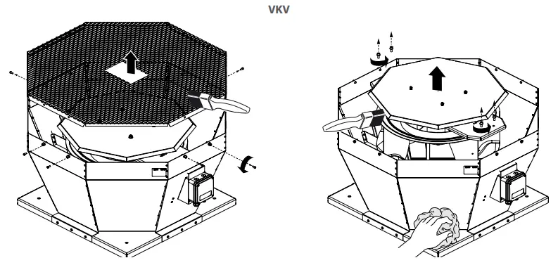
VKV 2E 190, VKV 2E 220, VKV 2E 225, VKV 4E 225, VKV 2E 250, VKV 4E 250, VKV 4E 280, VKV 2E 310, VKV 4E 310, VKV 4D 310, VKV 4E 355, VKV 4D 355
with a hinged cover and a motor 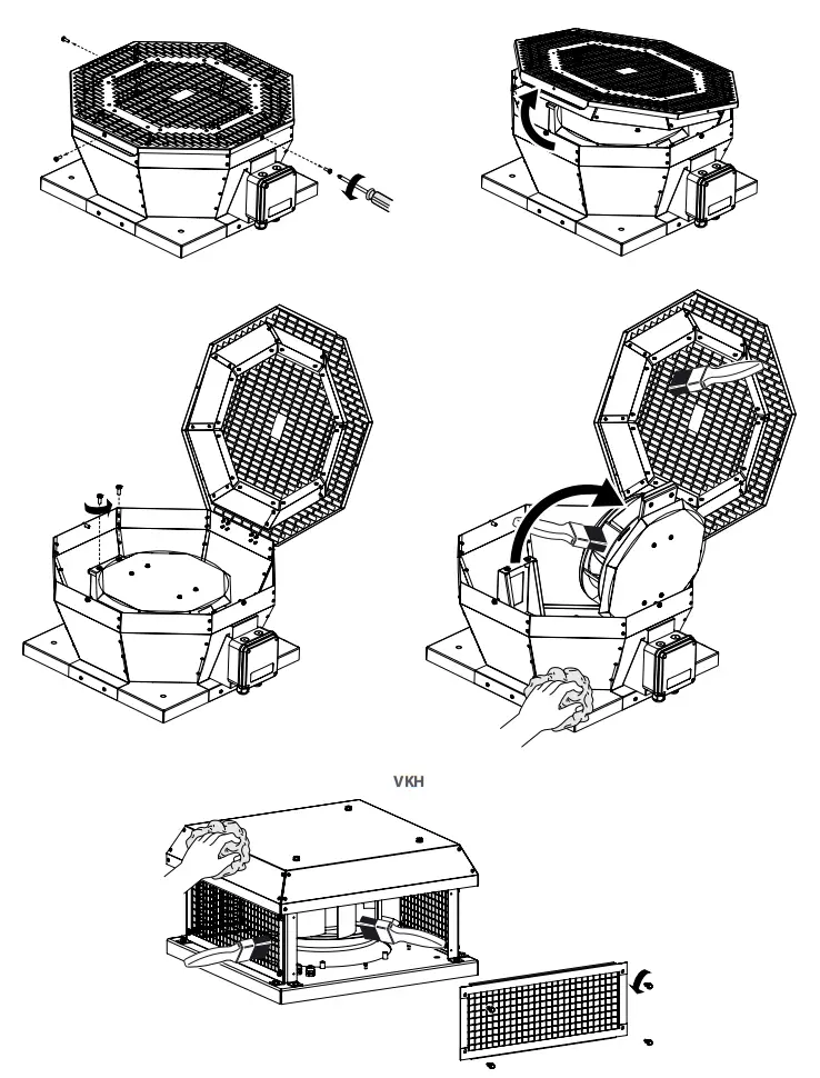
TROUBLESHOOTING
| Problem Possible reasons Elimination | ||
| The fan will not start. | No power supply. | Check the main switch. Check the electrical connections according to the wiring diagram. |
| Jammed motor. | Carefully check the fan impeller for possible seizure and eliminate it, if necessary. If the impeller is in order, replace the electric motor. | |
| The switching equipment activates upon fan start-up. | Short circuit in the fan or the electric circuit between the fan and the switching equipment. | Eliminate the cause of a short circuit. |
| Excessive current consumption due to an overload in the electric mains. | Eliminate the cause of excessive current consumption. | |
| Improper fan starting method. | Use a soft starter or frequency converter to start the motor (see “Asynchronous Electric Motor Starting Methods” in the “Connection to power mains” section). | |
| Improper switching equipment. | Re-select the switching equipment in accordance with the current regulations and equipment specifications. | |
| The installed switching equipment is of poor quality or its actual performance falls short of the rated values stated by the manufacturer. | Re-select the switching equipment by choosing a unit that successfully passed commutation and load tests and has a technical compliance certificate. The selection should be limited to the top five foreign switching equipment manufacturers. | |
| The fan fails to reach the required rotation speed due to serious overheating of the fan motor. | Fan motor overloaded. | Eliminate the overload. |
| Improper fan starting method. | Use a soft starter or frequency converter to start the motor (see”Asynchronous Electric Motor Starting Methods” in the “Connection to power mains” section). | |
| The fan motor runs at overload capacity with current consumption in excess of the rated value. | The fan supplies more air than expected upon motor capacity selection. | Measure network resistance. Throttle down the network (add aerodynamic resistance to the air duct network). |
| Wrong motor phasing.The impeller rotates in the opposite direction of the arrow on the fan casing. | If necessary, change the impeller rotation direction by changing the phase sequence on the electric motor terminals. | |
| Air ducts are clogged. | Clean the air duct or the impeller. | |
| The fan supplies more air than expected. | The resistance values used during the ventilation network calculations are too conservative. | Check the air ducts for proper shape and cross-section as well as for any dampers present. |
| The cross-section of air ducts increased and their number reduced during the installation. | Throttle down the network (add aerodynamic resistance to the air duct network). | |
| Wrong choice of the fan. | Replace the fan with a unit of proper standard size. |
| The fan supplies less air than expected. | Wrong calculation of the ventilation network and wrong selection of the fan. | Re-calculate the network parameters and select a matching fan. |
| The network resistance exceeds the design calculations. | Re-arrange the ventilation network to decrease its aerodynamic resistance. | |
| Wrong direction of the impeller rotation. | If necessary, change the impeller rotation direction by changing the phase sequence on the electric motor terminals (see the “Commissioning” section). | |
| Air leak through a loose air duct connection. | Eliminate the air leak. Seal the air duct connection. | |
| Impeller or air duct contamination with foreign objects or debris. | Clean the impeller or the air ducts from foreign objects or debris. | |
| Excessive noise or vibration both inside the fan and in the circuit. | Loose screw connections. | Check the screw connections for proper tightness. |
| No flexible joints between the fan and the ventilation network on the suction and discharge sides. | Install flexible joints. | |
| Loose connection of valves and dampers to the air ducts. | Tighten up the fasteners of valves and dampers. | |
| Impeller or air duct contamination with foreign objects or debris. | Clean the impeller or the air ducts from foreign objects or debris. | |
| Worn bearings. | Replace the bearings. | |
| Unstable power supply, unstable motor operation. | Check the stability of power supply parameters and electric motor operation. |
STORAGE AND TRANSPORTATION REGULATIONS
- Store the unit in the manufacturer’s original packaging box in a dry closed ventilated premise with a temperature range from +5 ˚C to +40 ˚C and relative humidity up to 70 %.
- The storage environment must not contain aggressive vapors and chemical mixtures provoking corrosion, insulation, and sealing deformation.
- Use suitable hoist machinery for handling and storage operations to prevent possible damage to the unit.
- Follow the handling requirements applicable for the particular type of cargo.
- The unit can be carried in the original packaging by any mode of transport providing proper protection against precipitation and mechanical damage. The unit must be transported only in the working position.
- Avoid sharp blows, scratches, or rough handling during loading and unloading.
- Prior to the initial power-up after transportation at low temperatures, allow the unit to warm up at operating temperature for at least 3-4 hours.
MANUFACTURER’S WARRANTY
The product is in compliance with EU norms and standards on low voltage guidelines and electromagnetic compatibility. We hereby declare that the product complies with the provisions of the Electromagnetic Compatibility (EMC) Directive 2014/30/EU of the European Parliament and of the Council, Low Voltage Directive (LVD) 2014/35/EU of the European Parliament and of the Council and CE-marking Council Directive 93/68/EEC. This certificate is issued following a test carried out on samples of the product referred to above. The manufacturer hereby warrants normal operation of the unit for 24 months after the retail sale date provided the user’s observance of the transportation, storage, installation, and operation regulations. Should any malfunctions occur in the course of the unit operation through the Manufacturer’s fault during the guaranteed period of operation, the user is entitled to get all the faults eliminated by the manufacturer by means of warranty repair at the factory free of charge. The warranty repair includes work specific to the elimination of faults in the unit operation to ensure its intended use by the user within the guaranteed period of operation. The faults are eliminated by means of replacement or repair of the unit components or a specific part of the such unit component.
The warranty repair does not include:
- routine technical maintenance
- unit installation/dismantling
- unit setup
To benefit from a warranty repair, the user must provide the unit, the user’s manual with the purchase date stamp, and the payment paperwork certifying the purchase. The unit model must comply with the one stated in the user’s manual. Contact the Seller for warranty service.
The manufacturer’s warranty does not apply to the following cases:
- User’s failure to submit the unit with the entire delivery package as stated in the user’s manual including submission with missing component parts previously dismounted by the user.
- Mismatch of the unit model and the brand name with the information stated on the unit packaging and in the user’s manual.
- User’s failure to ensure timely technical maintenance of the unit.
- External damage to the unit casing (excluding external modifications as required for installation) and internal components caused by the user.
- Redesign or engineering changes to the unit.
- Replacement and use of any assemblies, parts, and components not approved by the manufacturer.
- Unit misuse.
- Violation of the unit installation regulations by the user.
- Violation of the unit control regulations by the user.
- Unit connection to power mains with a voltage different from the one stated in the user’s manual.
- Unit breakdown due to voltage surges in power mains.
- Discretionary repair of the unit by the user.
- Unit repair by any persons without the manufacturer’s authorization.
- Expiration of the unit warranty period.
- Violation of the unit transportation regulations by the user.
- Violation of the unit storage regulations by the user.
- Wrongful actions against the unit are committed by third parties.
- Unit breakdown due to circumstances of insuperable force (fire, flood, earthquake, war, hostilities of any kind, blockades).
- Missing seals if provided by the user’s manual.
- Failure to submit the user’s manual with the unit purchase date stamp.
- Missing payment paperwork certifying the unit purchase.
![]() FOLLOWING THE REGULATIONS STIPULATED HEREIN WILL ENSURE A LONG AND TROUBLE-FREE OPERATION OF THE UNIT.
FOLLOWING THE REGULATIONS STIPULATED HEREIN WILL ENSURE A LONG AND TROUBLE-FREE OPERATION OF THE UNIT.![]() USER’S WARRANTY CLAIMS SHALL BE SUBJECT TO REVIEW ONLY UPON PRESENTATION OF THE UNIT, THE PAYMENT DOCUMENT AND THE USER’S MANUAL WITH THE PURCHASE DATE STAMP.
USER’S WARRANTY CLAIMS SHALL BE SUBJECT TO REVIEW ONLY UPON PRESENTATION OF THE UNIT, THE PAYMENT DOCUMENT AND THE USER’S MANUAL WITH THE PURCHASE DATE STAMP.
CERTIFICATE OF ACCEPTANCE
| Unit Type | Centrifugal roof fan |
| Model | |
| Serial Number | |
| Manufacture Date | |
| Quality Inspector’s Stamp |
SELLER INFORMATION
| Seller | |
| Address | |
| Phone Number | |
| Purchase Date | |
| This is to certify acceptance of the complete unit delivery with the user’s manual. The warranty terms are acknowledged and accepted. | |
| Customer’s Signature | |
![]()
WARRANTY CARD
| Unit Type | Centrifugal roof fan |
| Model | |
| Serial Number | |
| Manufacture Date | |
| Purchase Date | |
| Warranty Period | |
| Seller |
![]()

http://vents.ua/


