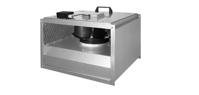
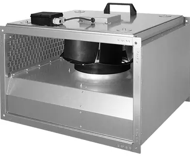
VENTS VKPFI Centrifugal Rectangular Duct Fan
SAFETY REQUIREMENTS
- This appliance can be used by children aged from 8 years and above and persons with reduced physical, sensory or mental capabilities or lack of experience and knowledge if they have been given supervision or instruction concerning use of the appliance in a safe way and understand the hazards involved
- Cleaning and user maintenance shall not be made by children without supervision
- Children shall not play with the appliance.
- Connection to the mains must be made through a disconnecting device, which is integrated into the fixed wiring system in accordance with the wiring rules for design of electrical units, and has a contact separation in all poles that allows for full disconnection under overvoltage category III conditions.
- If the supply cord is damaged, it must be replaced by the manufacturer, its service agent, or similarly qualified persons in order to avoid a safety hazard.
- This appliance can be used by children aged from 8 years and above and persons with reduced physical, sensory or mental capabilities or lack of experience and knowledge if they have been given supervision or instruction concerning use of the appliance in a safe way and understand the hazards involved
- Cleaning and user maintenance shall not be made by children without supervision
- Children shall not play with the appliance.
- Fixing means for attachment to the ceiling such as hooks or other devices shall be fixed with a sufficient strength to withstand 4 times the weight of the appliance.
- The mounting of the suspension system shall be performed by the manufacturer, its service agent or suitably qualified persons.
- The appliance is to be installed so that the blades are more than 2.3 m above the floor. Precautions must be taken to avoid the back-flow of gases into the room from the open flue of gas or other fuel-burning appliances.
- The installation site of the fan must have protective elements that prevent foreign objects from entering the fan.
- When starting, setting up and operating the fan, the exhaust and supply spigots must be protected to prevent injury from the rotating parts of the fan.
- Do not attach the product to the support using glue or adhesives. Use only the fastening method specified in the «User’s manual». All operations described in this manual must be performed by qualified personnel only, properly trained and qualified to install, make electrical connections and maintain ventilation units.
- Do not attempt to install the product, connect it to the mains, or perform maintenance yourself. This is unsafe and impossible without special knowledge.
- Disconnect the power supply prior to any operations with the unit.
- All user’s manual requirements as well as the provisions of all the applicable local and national construction, electrical, and technical norms and standards must be observed when installing and operating the unit.
- Disconnect the unit from the power supply prior to any connection, servicing, maintenance, and repair operations.
- Only qualified electricians with a work permit for electrical units up to 1000 V are allowed for installation. The present user’s manual should be carefully read before beginning works.
- Check the unit for any visible damage of the impeller, the casing, and the grille before starting installation. The casing internals must be free of any foreign objects that can damage the impeller blades.
- While mounting the unit, avoid compression of the casing! Deformation of the casing may result in motor jam and excessive noise.
- Misuse of the unit and any unauthorized modifications are not allowed.
- Do not expose the unit to adverse atmospheric agents (rain, sun, etc.).
- Transported air must not contain any dust or other solid impurities, sticky substances, or fibrous materials.
- Do not use the unit in a hazardous or explosive environment containing spirits, gasoline, insecticides, etc.
- Do not close or block the intake or extract vents in order to ensure the efficient air flow.
- Do not sit on the unit and do not put objects on it.
- The information in this user’s manual was correct at the time of the document’s preparation. The Company reserves the right to modify the technical characteristics, design, or configuration of its products at any time in order to incorporate the latest technological developments. Never touch the unit with wet or damp hands.
- Never touch the unit when barefoot.
PURPOSE
- The duct rectangular fan is designed for supply and exhaust ventilation of domestic, public and industrial premises with high requirements to the noise level and with limited space for mounting.
- The unit is rated for continuous operation.
- The unit is a component part and is not designed for stand-alone operation.
- Transported air must not contain any flammable or explosive mixtures, evaporation of chemicals, sticky substances, fibrous materials, coarse dust, soot and oil particles or environments favorable for the formation of hazardous substances (toxic substances, dust, pathogenic germs).
DELIVERY SET
NAME : NUMBER
- Fan : 1 pc.
- User’s manual : 1 pc.
- Packing box : 1 pc.
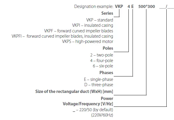
DESIGNATION KEY
TECHNICAL DATA
The unit is designed for indoor application with the ambient temperature ranging from 0 °C up +45 °C and relative humidity up to 80 %.
The unit is rated as a Class I electrical appliance.
The unit design is constantly being improved, thus some models may be slightly different from those described in this manual.
| VKP/VKPI | 2E 400*200 | 2E 500*250 | 4E 500*300 | 4D 500*300 | |||||||||||
| Voltage [V] | 1~ 220-240 | 1~ 220-240 | 1~ 220-240 | 3~ 400 | |||||||||||
| Frequency [Hz] | 50 | 60 | 50 | 60 | 50 | 60 | 50 | 60 | |||||||
| Power [W] | 138 | 200 | 305 | 380 | 140 | 175 | 136 | 165 | |||||||
| Current [A] | 0.60 | 0.88 | 1.32 | 1.65 | 0.57 | 0.73 | 0.34 | 0.53 | |||||||
| Maximum air flow [m3/h] | 930 | 1070 | 1720 | 1850 | 1700 | 1855 | 1380 | 1620 | |||||||
| RPM [min-1] | 2600 | 2850 | 2550 | 2830 | 1390 | 1530 | 1360 | 1600 | |||||||
| Sound pressure level at 3 m distance [dBA] | 50/45* | 52/47* | 57/51* | 58/52* | 53/48* | 55/50* | 52/47* | 55/50* | |||||||
| Transported air temperature [°С] | -25…+45 | -25…+45 | -25…+45 | -25…+45 | -25…+45 | -25…+50 | -25…+65 | -25…+55 | |||||||
| Ingress protection rating of the unit | IPX4 | IPX4 | IPX4 | IPX4 | IPX4 | IPX4 | IPX4 | IPX4 | |||||||
| Electric motor IP rating | IP44 | IP44 | IP44 | IP44 | IP54 | IP54 | IP54 | IP54 | |||||||
| VKP/VKPI | 4E 600*300 | 4D 600*300 | 4E 600*350 | ||||||||||||
| Voltage [V] | 1~ 220-240 | 3~ 400 | 1~ 220-240 | ||||||||||||
| Frequency [Hz] | 50 | 60 | 50 | 60 | 50 | 60 | |||||||||
| Power [W] | 220 | 310 | 230 | 235 | 470 | 700 | |||||||||
| Current [A] | 0.9 | 1.38 | 0.52 | 0.53 | 2.37 | 3.15 | |||||||||
| Maximum air flow [m3/h] | 2470 | 2510 | 2530 | 2630 | 2950 | 3515 | |||||||||
| RPM [min-1] | 1400 | 1450 | 1360 | 1600 | 1370 | 1460 | |||||||||
| Sound pressure level at 3 m distance [dBA] | 52/46* | 52/46* | 51/45* | 53/47* | 52/47* | 53/47* | |||||||||
| Transported air temperature [°С] | -25…+45 | -25…+45 | -25…+70 | -25…+65 | -30…+80 | -30…+55 | |||||||||
| Ingress protection rating of the unit | IPX4 | IPX4 | IPX4 | IPX4 | IPX4 | IPX4 | |||||||||
| Electric motor IP rating | IP54 | IP54 | IP54 | IP54 | IP54 | IP54 | |||||||||
| VKP/VKPI | 4D 600*350 | 4D 1000*500 | 6D 1000*500 | ||||||||||||
| Voltage [V] | 3~ 400 Δ | 3~ 400 Y | 3~ 400 | 3~ 400 | |||||||||||
| Frequency [Hz] | 50 | 60 | 50 | 60 | 50 | 50 | |||||||||
| Power [W] | 510 | 750 | 380 | 515 | 3800 | 1198 | |||||||||
| Current [A] | 1.41 | 1.44 | 0.7 | 0.93 | 6.6 | 2,7 | |||||||||
| Maximum air flow [m3/h] | 2970 | 3410 | 2660 | 2730 | 15000 | 10500 | |||||||||
| RPM [min-1] | 1415 | 1610 | 1235 | 1220 | 1360 | 900 | |||||||||
| Sound pressure level at 3 m distance [dBA] | 51/46* | 53/46* | 50/46* | 50/46* | 70 | 69 | |||||||||
| Transported air temperature [°С] | -30…+60 | -30…+60 | -30…+80 | -30…+40 | -30…+60 | -25 …+50 | |||||||||
| Ingress protection rating of the unit | IPX4 | IPX4 | IPX4 | IPX4 | IPX4 | IPX4 | |||||||||
| Electric motor IP rating | IP54 | IP54 | IP54 | IP54 | IP54 | IP54 | |||||||||
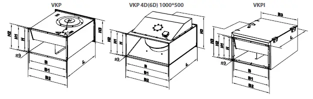
| Model | Dimensions [mm] | Weight [kg] | ||||||||||||||||||||||||
| B | B1 | B2 | H | H1 | H2 | H3 | L | |||||||||||||||||||
| VKP 2E 400*200 | 400 | 420 | 440 | 200 | 220 | 240 | 240 | 500 | 11.25 | |||||||||||||||||
| VKP 2E 500*250 | 500 | 520 | 540 | 250 | 270 | 290 | 290 | 640 | 17.88 | |||||||||||||||||
| VKP 4E 500*300 | 500 | 520 | 540 | 300 | 320 | 340 | 340 | 680 | 19.80 | |||||||||||||||||
| VKP 4D 500*300 | 500 | 520 | 540 | 300 | 320 | 340 | 340 | 680 | 19.80 | |||||||||||||||||
| VKP 4E 600*300 | 600 | 620 | 640 | 300 | 320 | 340 | 342 | 680 | 27.77 | |||||||||||||||||
| VKP 4D 600*300 | 600 | 620 | 640 | 300 | 320 | 340 | 342 | 680 | 27.77 | |||||||||||||||||
| VKP 4E 600*350 | 600 | 620 | 640 | 350 | 370 | 390 | 390 | 735 | 36.38 | |||||||||||||||||
| VKP 4D 600*350 | 600 | 620 | 640 | 350 | 370 | 390 | 390 | 735 | 36.38 | |||||||||||||||||
| B | B1 | B2 | H | H1 | H2 | H3 | L | |||||||||||||||||||
| VKP 4D(6D) 1000*500 | 1000 | 1020 | 1040 | 500 | 520 | 540 | 720 | 1150 | 126.0 | |||||||||||||||||
| B | B1 | B2 | B3 | H | H1 | H2 | H3 | L | ||||||||||||||||||
| VKPI 2E 400*200 | 400 | 420 | 440 | 500 | 200 | 220 | 240 | 360 | 500 | 24.5 | ||||||||||||||||
| VKPI 2E 500*250 | 500 | 520 | 540 | 600 | 250 | 270 | 290 | 410 | 640 | 27.6 | ||||||||||||||||
| VKPI 4E 500*300 | 500 | 520 | 540 | 600 | 300 | 320 | 340 | 460 | 680 | 37.2 | ||||||||||||||||
| VKPI 4D 500*300 | 500 | 520 | 540 | 600 | 300 | 320 | 340 | 460 | 680 | 37.2 | ||||||||||||||||
| VKPI 4E 600*300 | 600 | 620 | 640 | 700 | 300 | 320 | 340 | 460 | 680 | 43.5 | ||||||||||||||||
| VKPI 4D 600*300 | 600 | 620 | 640 | 700 | 300 | 320 | 340 | 460 | 680 | 43.5 | ||||||||||||||||
| VKPI 4E 600*350 | 600 | 620 | 640 | 700 | 350 | 370 | 390 | 530 | 735 | 56.2 | ||||||||||||||||
| VKPI 4D 600*350 | 600 | 620 | 640 | 700 | 350 | 370 | 390 | 530 | 735 | 56.2 | ||||||||||||||||
| VKP | 4D 700*400 | 4D 800*500 | VKPS 4E 600*350 | |
| Voltage [V] | 3~ 400 | 3~ 400 | 1~ 220-240 | |
| Frequency [Hz] | 50 | 50 | 50 | 60 |
| Power [W] | 828 | 1508 | 447 | 679 |
| Current [A] | 1,62 | 2,71 | 1,97 | 2,99 |
| Maximum air flow [m3/h] | 5580 | 7800 | 4070 | 4500 |
| RPM [min-1] | 1418 | 1440 | 1380 | 1600 |
| Sound pressure level at 3 m distance [dBA] | 57 | 58 | 54 | 56 |
| Transported air temperature [°С] | -30…+60 | -30…+60 | -30…+60 | -30…+60 |
| Ingress protection rating of the unit | IPX4 | IPX4 | IPX4 | IPX4 |
| Electric motor IP rating | IP54 | IP54 | IP54 | IP54 |
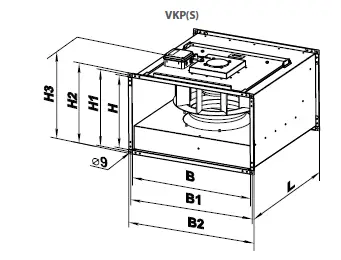
| Model | Dimensions [mm] | Weight [kg] | |||||||
| B | B1 | B2 | H | H1 | H2 | H3 | L | ||
| VKPS 4E 600*350 | 600 | 620 | 640 | 350 | 370 | 390 | 428 | 652 | 30 |
| VKP 4D 700*400 | 700 | 720 | 740 | 400 | 420 | 440 | 475 | 753 | 41 |
| VKP 4D 800*500 | 800 | 820 | 840 | 500 | 520 | 540 | 578 | 903 | 54 |
| VKPF/VKPFI | 4E 400*200 | 4D 400*200 | 4E 500*250 | 4D 500*250 | 6E 500*250 |
| Unit voltage [V/50 (60) Hz] | 1~ 230 | 3~ 400 | 1~ 230 | 3~ 400 | 1~ 230 |
| Power [W] | 295 | 282 | 535 | 570 | 244 |
| Current [A] | 1.32 | 0.60 | 2.49 | 0.94 | 1.22 |
| Maximum air flow [m3/h] | 1440 | 1470 | 1750 | 1850 | 1460 |
| RPM [min-1] | 1350 | 1300 | 1250 | 1270 | 910 |
| Sound pressure level at 3 m distance [dBA] | 50/42* | 52/43* | 53/44* | 54/44* | 45/37* |
| Transported air temperature [°С] | -25…+40 | -25…+45 | -20…+40 | -20…+40 | -20…+50 |
| Ingress protection rating of the unit | IPX4 | IPX4 | IPX4 | IPX4 | IPX4 |
| Electric motor IP rating | IP54 | IP54 | IP54 | IP54 | IP54 |
| VKPF/VKPFI | 6D 500*250 | 4E 500*300 | 4D 500*300 | 6E 500*300 | 6D 500*300 |
| Unit voltage [V/50 (60) Hz] | 3~ 400 | 1~ 230 | 3~ 400 | 1~ 230 | 3~ 400 |
| Power [W] | 274 | 710 | 855 | 283 | 303 |
| Current [A] | 0.67 | 3.10 | 1.70 | 1.59 | 0.8 |
| Maximum air flow [m3/h] | 1490 | 2350 | 2350 | 1550 | 1620 |
| RPM [min-1] | 930 | 1230 | 1300 | 890 | 910 |
| Sound pressure level at 3 m distance [dBA] | 45/38* | 57/47* | 56/47* | 47/39* | 51/41* |
| Transported air temperature [°С] | -20…+60 | -25…+70 | -20…+50 | -20…+70 | -20…+60 |
| Ingress protection rating of the unit | IPX4 | IPX4 | IPX4 | IPX4 | IPX4 |
| Electric motor IP rating | IP54 | IP54 | IP54 | IP54 | IP54 |
| VKPF/VKPFI | 4E 600*300 | 4D 600*300 | 6E 600*300 | 6D 600*300 | 4E 600*350 |
| Unit voltage [V/50 (60) Hz] | 1~ 230 | 3~ 400 | 1~ 230 | 3~ 400 | 1~ 230 |
| Power [W] | 1240 | 1560 | 419 | 397 | 2840 |
| Current [A] | 6.45 | 2.73 | 2.05 | 0.78 | 13.90 |
| Maximum air flow [m3/h] | 2950 | 3740 | 2260 | 2320 | 4260 |
| RPM [min-1] | 1210 | 1310 | 870 | 920 | 1260 |
| Sound pressure level at 3 m distance [dBA] | 59/51* | 57/50* | 50/42* | 49/41* | 59/51* |
| Transported air temperature [°С] | -25…+50 | -25…+65 | -20…+70 | -20…+70 | -20…+40 |
| Ingress protection rating of the unit | IPX4 | IPX4 | IPX4 | IPX4 | IPX4 |
| Electric motor IP rating | IP54 | IP54 | IP54 | IP54 | IP54 |
| VKPF/VKPFI | 4D 600*350 | 6E 600*350 | 6D 600*350 | 4D 700*400 |
| Unit voltage [V/50 (60) Hz] | 3~ 400 | 1~ 230 | 3~ 400 | 3~ 400 |
| Power [W] | 2460 | 720 | 743 | 3630 |
| Current [A] | 3.93 | 3.6 | 1.47 | 6.00 |
| Maximum air flow [m3/h] | 5020 | 2755 | 3310 | 6450 |
| RPM [min-1] | 1300 | 820 | 940 | 1320 |
| Sound pressure level at 3 m distance [dBA] | 60/52* | 51/43* | 55/46* | 65/56* |
| Transported air temperature [°С] | -20…+40 | -20…+60 | -20…+70 | -25…+40 |
| Ingress protection rating of the unit | IPX4 | IPX4 | IPX4 | IPX4 |
| Electric motor IP rating | IP54 | IP54 | IP54 | IP54 |
| VKPF/VKPFI | 6D 700*400 | 4D 800*500 | 6D 800*500 | 8D 800*500 |
| Unit voltage [V/50 (60) Hz] | 3~ 400 | 3~ 400 | 3~ 400 | 3~ 400 |
| Power [W] | 1150 | 5850 | 2790 | 1377 |
| Current [A] | 2.3 | 9.35 | 5.18 | 3.40 |
| Maximum air flow [m3/h] | 4050 | 8120 | 7610 | 5620 |
| RPM [min-1] | 890 | 1140 | 830 | 710 |
| Sound pressure level at 3 m distance [dBA] | 58/49* | 67/61* | 59/53* | 58/49 |
| Transported air temperature [°С] | -20…+70 | -25…+40 | -20…+50 | -20…+40 |
| Ingress protection rating of the unit | IPX4 | IPX4 | IPX4 | IPX4 |
| Electric motor IP rating | IP54 | IP54 | IP54 | IP54 |
| VKPF/VKPFI | 6D 900*500 | 8D 900*500 | 6D 1000*500 | 8D 1000*500 |
| Unit voltage [V/50 (60) Hz] | 3~ 400 | 3~ 400 | 3~ 400 | 3~ 400 |
| Power [W] | 3870 | 2000 | 3870 | 2000 |
| Current [A] | 7.0 | 4.1 | 7.0 | 4.1 |
| Maximum air flow [m3/h] | 9540 | 7175 | 9540 | 7175 |
| RPM [min-1] | 930 | 680 | 930 | 680 |
| Sound pressure level at 3 m distance [dBA] | 61/55* | 59/50* | 61/55* | 59/51* |
| Transported air temperature [°С] | -20…+55 | -20…+40 | -20…+55 | -20…+40 |
| Ingress protection rating of the unit | IPX4 | IPX4 | IPX4 | IPX4 |
| Electric motor IP rating | IP54 | IP54 | IP54 | IP54 |
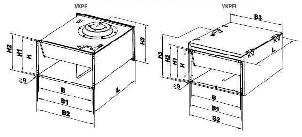
| Model | Dimensions [mm] | Weight [kg] | |||||||||||||||||||||||||
| B | B1 | B2 | H | H1 | H2 | H3 | L | ||||||||||||||||||||
| VKPF 4E 400*200 | 400 | 420 | 440 | 200 | 220 | 240 | 255 | 500 | 17.5 | ||||||||||||||||||
| VKPF 4D 400*200 | 400 | 420 | 440 | 200 | 220 | 240 | 255 | 500 | 17.5 | ||||||||||||||||||
| VKPF 4E 500*250 | 500 | 520 | 540 | 250 | 270 | 290 | 335 | 640 | 24 | ||||||||||||||||||
| VKPF 4D 500*250 | 500 | 520 | 540 | 250 | 270 | 290 | 335 | 640 | 24 | ||||||||||||||||||
| VKPF 6E 500*250 | 500 | 520 | 540 | 250 | 270 | 290 | 335 | 640 | 24 | ||||||||||||||||||
| VKPF 6D 500*250 | 500 | 520 | 540 | 250 | 270 | 290 | 335 | 640 | 24 | ||||||||||||||||||
| VKPF 4E 500*300 | 500 | 520 | 540 | 300 | 320 | 340 | 365 | 680 | 33 | ||||||||||||||||||
| VKPF 4D 500*300 | 500 | 520 | 540 | 300 | 320 | 340 | 365 | 680 | 33 | ||||||||||||||||||
| VKPF 6E 500*300 | 500 | 520 | 540 | 300 | 320 | 340 | 365 | 680 | 33 | ||||||||||||||||||
| VKPF 6D 500*300 | 500 | 520 | 540 | 300 | 320 | 340 | 365 | 680 | 33 | ||||||||||||||||||
| VKPF 4E 600*300 | 600 | 620 | 640 | 300 | 320 | 340 | 375 | 680 | 35 | ||||||||||||||||||
| VKPF 4D 600*300 | 600 | 620 | 640 | 300 | 320 | 340 | 375 | 680 | 35 | ||||||||||||||||||
| VKPF 6E 600*300 | 600 | 620 | 640 | 300 | 320 | 340 | 375 | 680 | 35 | ||||||||||||||||||
| VKPF 6D 600*300 | 600 | 620 | 640 | 300 | 320 | 340 | 375 | 680 | 35 | ||||||||||||||||||
| VKPF 4E 600*350 | 600 | 620 | 640 | 350 | 370 | 390 | 425 | 735 | 49.5 | ||||||||||||||||||
| VKPF 4D 600*350 | 600 | 620 | 640 | 350 | 370 | 390 | 425 | 735 | 49.5 | ||||||||||||||||||
| VKPF 6E 600*350 | 600 | 620 | 640 | 350 | 370 | 390 | 425 | 735 | 49.5 | ||||||||||||||||||
| VKPF 6D 600*350 | 600 | 620 | 640 | 350 | 370 | 390 | 425 | 735 | 49.5 | ||||||||||||||||||
| VKPF 4D 700*400 | 700 | 720 | 740 | 400 | 420 | 440 | 480 | 780 | 60 | ||||||||||||||||||
| VKPF 6D 700*400 | 700 | 720 | 740 | 400 | 420 | 440 | 480 | 780 | 56 | ||||||||||||||||||
| VKPF 4D 800*500 | 800 | 820 | 840 | 500 | 520 | 540 | 580 | 820 | 74 | ||||||||||||||||||
| VKPF 6D 800*500 | 800 | 820 | 840 | 500 | 520 | 540 | 580 | 820 | 70 | ||||||||||||||||||
| VKPF 8D 800*500 | 800 | 820 | 840 | 500 | 520 | 540 | 580 | 820 | 70 | ||||||||||||||||||
| VKPF 6D 900*500 | 900 | 920 | 940 | 500 | 520 | 540 | 580 | 954 | 90 | ||||||||||||||||||
| VKPF 8D 900*500 | 900 | 920 | 940 | 500 | 520 | 540 | 580 | 954 | 90 | ||||||||||||||||||
| VKPF 6D 1000*500 | 1000 | 1020 | 1040 | 500 | 520 | 540 | 580 | 954 | 95 | ||||||||||||||||||
| VKPF 8D 1000*500 | 1000 | 1020 | 1040 | 500 | 520 | 540 | 580 | 954 | 95 | ||||||||||||||||||
| B | B1 | B2 | B3 | H | H1 | H2 | H3 | L | |||||||||||||||||||
| VKPFI 4E 400*200 | 400 | 420 | 440 | 470 | 200 | 220 | 240 | 360 | 500 | 29 | |||||||||||||||||
| VKPFI 4D 400*200 | 400 | 420 | 440 | 470 | 200 | 220 | 240 | 360 | 500 | 29 | |||||||||||||||||
| VKPFI 4E 500*250 | 500 | 520 | 540 | 570 | 250 | 270 | 290 | 410 | 640 | 40.5 | |||||||||||||||||
| VKPFI 4D 500*250 | 500 | 520 | 540 | 570 | 250 | 270 | 290 | 410 | 640 | 40.5 | |||||||||||||||||
| VKPFI 6E 500*250 | 500 | 520 | 540 | 570 | 250 | 270 | 290 | 410 | 640 | 40.5 | |||||||||||||||||
| VKPFI 6D 500*250 | 500 | 520 | 540 | 570 | 250 | 270 | 290 | 410 | 640 | 40.5 | |||||||||||||||||
| VKPFI 4E 500*300 | 500 | 520 | 540 | 570 | 300 | 320 | 340 | 460 | 680 | 52.5 | |||||||||||||||||
| VKPFI 4D 500*300 | 500 | 520 | 540 | 570 | 300 | 320 | 340 | 460 | 680 | 52.5 | |||||||||||||||||
| VKPFI 6E 500*300 | 500 | 520 | 540 | 570 | 300 | 320 | 340 | 460 | 680 | 52.5 | |||||||||||||||||
| VKPFI 6D 500*300 | 500 | 520 | 540 | 570 | 300 | 320 | 340 | 460 | 680 | 52.5 | |||||||||||||||||
| VKPFI 4E 600*300 | 600 | 620 | 640 | 670 | 300 | 320 | 340 | 480 | 680 | 56 | |||||||||||||||||
| VKPFI 4D 600*300 | 600 | 620 | 640 | 670 | 300 | 320 | 340 | 480 | 680 | 56 | |||||||||||||||||
| VKPFI 6E 600*300 | 600 | 620 | 640 | 670 | 300 | 320 | 340 | 480 | 680 | 56 | |||||||||||||||||
| VKPFI 6D 600*300 | 600 | 620 | 640 | 670 | 300 | 320 | 340 | 480 | 680 | 56 | |||||||||||||||||
| VKPFI 4E 600*350 | 600 | 620 | 640 | 670 | 350 | 370 | 390 | 530 | 735 | 72 | |||||||||||||||||
| VKPFI 4D 600*350 | 600 | 620 | 640 | 670 | 350 | 370 | 390 | 530 | 735 | 72 | |||||||||||||||||
| VKPFI 6E 600*350 | 600 | 620 | 640 | 670 | 350 | 370 | 390 | 530 | 735 | 72 | |||||||||||||||||
| VKPFI 6D 600*350 | 600 | 620 | 640 | 670 | 350 | 370 | 390 | 530 | 735 | 72 | |||||||||||||||||
| VKPFI 4D 700*400 | 700 | 720 | – | 800 | 400 | 420 | – | 620 | 880 | 103 | |||||||||||||||||
| VKPFI 6D 700*400 | 700 | 720 | – | 800 | 400 | 420 | – | 620 | 880 | 99 | |||||||||||||||||
| VKPFI 6D 800*500 | 800 | 820 | – | 900 | 500 | 520 | – | 720 | 935 | 120 | |||||||||||||||||
| VKPFI 4D 800*500 | 800 | 820 | – | 900 | 500 | 520 | – | 720 | 935 | 127 | |||||||||||||||||
| VKPFI 8D 800*500 | 800 | 820 | – | 900 | 500 | 520 | – | 720 | 935 | 120 | |||||||||||||||||
| VKPFI 6D 900*500 | 900 | 920 | – | 1000 | 500 | 520 | – | 720 | 1000 | 142 | |||||||||||||||||
| VKPFI 8D 900*500 | 900 | 920 | – | 1000 | 500 | 520 | – | 720 | 1000 | 142 | |||||||||||||||||
| VKPFI 6D 1000*500 | 1000 | 1020 | – | 1100 | 500 | 520 | – | 720 | 1000 | 150 | |||||||||||||||||
| VKPFI 8D 1000*500 | 1000 | 1020 | – | 1100 | 500 | 520 | – | 720 | 1000 | 150 | |||||||||||||||||
MOUNTING AND SET-UP
BEFORE MOUNTING MAKE SURE THE CASING DOES NOT CONTAIN ANY FOREIGN OBJECTS (E.G. FOIL, PAPER). WHILE INSTALLING THE UNIT ENSURE CONVENIENT ACCESS FOR SUBSEQUENT MAINTENANCE AND REPAIR.
- The fan can operate at any position.
- When positioned under the ceiling, it is advisable to mount the fan with the motor cover downwards for easy access to the terminal box and the motor.
- Check the fan power cables for integrity and make sure the impeller has smooth rotation prior to mounting.
- Install flexible connectors on both sides of the fan.
- Mount the fan in such a way that the arrow on the fan casing matches the air flow direction in the system.
- The fan should always be installed on its own hangers so that it does not load the flexible connectors and the connected air ducts. The most suitable mounting option is fixing the unit to the ceiling with anchors or suspending it on perforated metal plates.
- Before mounting, apply a self-adhesive seal to the end surfaces of the fan.
- Connect the fan to the air ducts with M8 bolts and nuts.
- Since the fan belongs to Class 1 in terms of electrical hazard protection proper grounding is a must:
- the PE terminal must be connected to the protective ground.
The fan design is constantly being improved, thus some models may be slightly different from those described in this manual.
VARIANT OF FAN MOUNTING BETWEEN SEGMENTS OF RECTANGULAR AIR DUCTS
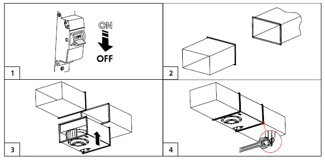
DISCONNECT THE POWER SUPPLY PRIOR TO ANY OPERATIONS WITH THE UNIT.
CONNECTION OF THE UNIT TO POWER MAINS IS ALLOWED BY A QUALIFIED ELECTRICIAN WITH A WORK PERMIT FOR THE ELECTRIC UNITS UP TO 1000 V AFTER CAREFUL READING OF THE PRESENT USER’S MANUAL.
THE RATED ELECTRICAL PARAMETERS OF THE UNIT ARE GIVEN ON THE MANUFACTURER’S LABEL.
- Depending on the fan type it is rated for connection either to single-phase AC 230 V/50/60 Hz or three-phase AC 380-400 V/50/60 Hz power mains.
- The connection must be made using durable, insulated and heat-resistant conductors (cables, wires).
- The external lead-in must be equipped with a circuit breaker built into the stationary wiring to disconnect all the mains phases.
- The QF external circuit breaker location must ensure free access for quick shutdown of the fan.
- The trip current must be in compliance with current consumption.
- The recommended rated current of the circuit beaker and the conductor cross section for various types of fans are shown in the table. The given conductor cross sections are for reference only.
- The actual conductor cross–section selection must be based on its type, the maximum permissible heating, insulation, length and installation method (in the air, pipes or inside walls).
- The recommended type of circuit breakers is D.
The recommended circuit breaker rated current and conductor cross section
| Model | Rated current of the circuit breaker | Recommended cable, n x S, where n is the number of wires, and S is the cross section in mm2 |
| VKP, VKPI 2E 400*200 | 3 | 3 x 0.75 |
| VKP, VKPI 2E 500*250 | 6 | 3 x 0.75 |
| VKP, VKPI 4E 500*300 | 2 | 3 x 0.75 |
| VKP, VKPI 4D 500*300 | 2 | 5 x 0.75 |
| VKP, VKPI 4E 600*300 | 4 | 5 x 0.75 |
| VKP, VKPI 4D 600*300 | 2 | 5 x 0.75 |
| VKP, VKPI 4E 600*350 | 10 | 3 x 1.5 |
| VKP, VKPI 4D 600*350 (400 Δ) | 4 | 5 x 0.75 |
| VKP, VKPI 4D 600*350 (400 Y) | 3 | 5 x 0.75 |
| VKP 4D 1000*500 | 25 | 5 x 1.5 |
| VKP 6D 1000*500 | 10 | 5 x 0.75 |
| VKPS 4E 600*350 | 10 | 3 x 0.75 |
| VKP 4D 700*400 | 6 | 5 x 0.75 |
| VKP 4D 800*500 | 10 | 5 x 0.75 |
| VKPF, VKPFI 4E 400*200 | 4 | 3 x 0.75 |
| VKPF, VKPFI 4D 400*200 | 2 | 5 x 0.75 |
| VKPF, VKPFI 4E 500*250 | 10 | 3 x 0.75 |
| VKPF, VKPFI 4D 500*250 | 3 | 5 x 0.75 |
| VKPF, VKPFI 4E 500*300 | 10 | 3 x 0.75 |
| VKPF, VKPFI 4D 500*300 | 6 | 5 x 0.75 |
| VKPF, VKPFI 4E 600*300 | 20 | 3×1 |
| VKPF, VKPFI 4D 600*300 | 10 | 5×0.75 |
| VKPF, VKPFI 4E 600*350 | 40 | 3×1.5 |
| VKPF, VKPFI 4D 600*350 | 16 | 5×0.75 |
| VKPF, VKPFI 4D 700*400 | 20 | 5×1 |
| VKPF, VKPFI 4D 800*500 | 32 | 5 x 1.5 |
| VKPF, VKPFI 6E 500*250 | 4 | 3×0.75 |
| VKPF, VKPFI 6D 500*250 | 2 | 5×0.75 |
| VKPF, VKPFI 6E 500*300 | 6 | 3×0.75 |
| VKPF, VKPFI 6D 500*300 | 3 | 5×0.75 |
| VKPF, VKPFI 6E 600*300 | 10 | 3×0.75 |
| VKPF, VKPFI 6D 600*300 | 3 | 5×0.75 |
| VKPF, VKPFI 6E 600*350 | 16 | 3×0.75 |
| VKPF, VKPFI 6D 600*350 | 6 | 5×0.75 |
| VKPF, VKPFI 6D 700*400 | 10 | 5×0.75 |
| VKPF, VKPFI 6D 800*500 | 20 | 5×1 |
| VKPF, VKPFI 6D 900*500 | 25 | 5×1 |
| VKPF, VKPFI 6D 1000*500 | 25 | 5×1 |
| VKPF, VKPFI 8D 800*500 | 16 | 5×0.75 |
| VKPF, VKPFI 8D 900*500 | 16 | 5×0.75 |
| VKPF, VKPFI 8D 1000*500 | 16 | 5×0.75 |
- Wiring diagram for VKP/VKPI 2Е 400*200; VKP/VKPI 2Е 500*250; VKP/VKPI 4Е 500Х300; VKP/VKPI 4Е 600Х300; VKP/VKPI 4Е 600Х350; VKPS 4Е 600*350 units with a single-phase motor

- Wiring diagram for VKP/VKPI 4D 500*300 units (first option) with a three-phase motor, without thermal contacts

- Wiring diagram for VKP/VKPI 4D 500*300 (second option), VKP/VKPI 4D 600*300; VKP 4D 700*400; VKP 4D 800*500 units with a three-phase motor

- Wiring diagram for VKPF(I) 4E 400*200; VKPF(I) 4E 500*250; VKPF(I) 4E 500*250; VKPF(I) 6E 500*300; VKPF(I) 6E 500*300; VKPF(I) 4E 600*300; VKPF(I) 6E 600*300; VKPF(I) 4E 600*350; VKPF(I) 6E 600*350 fans with a single-phase motor

- VKPF(I) 6D 600*320;VKPF(I) 6D 500*300; VKPF(I) 4D 600*300; VKPF(I) 6D 600*300; VKPF(I) 4D 600*350; VKPF(I) 6D 600*350; VKPF(I) 4D 700*400; VKPF(I) 6D 700*400; VKPF(I) 4D 800*500; VKPF(I) 6D 800*500; VKPF(I) 8D 800*500; VKPF(I) 6D 900*500; VKPF(I) 8D 900*500; VKP 4D 1000*500; VKP 6D 1000*500; VKPF(I) 6D 1000*500; VKPF(I) 8D 1000*500 fans

- Recommended wiring diagram for a single-phase motor with thermal protection

- Recommended wiring diagram a three-phase motor with thermal protection

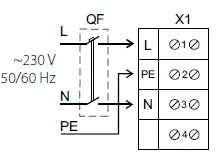
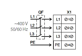
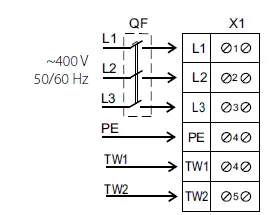
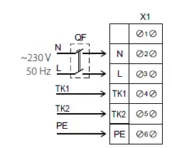
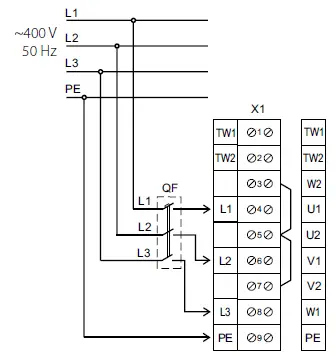
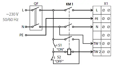
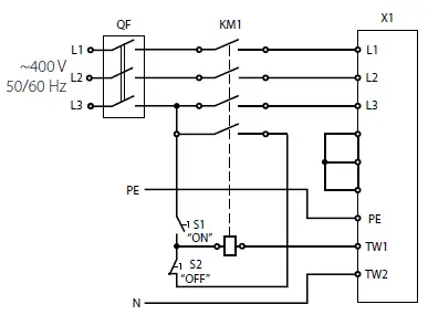
X1 – terminal block, QF – circuit breaker, KM1 – magnetic starter, S1, S2 – control buttons (QF, KM1, S1, S2 are not included in the delivery
set)
The TW1, TW2 (TK1, TK2) are the electrical leads of the normally closed contact of the motor overheating protection.
Connect the contact in series to power circuit of the magnetic starter coil KM1 that starts the motor after pressing the S1 button.
After the motor overheating the contact gets broken and switches the starter coil off to cut power off and stop the motor.
The QF circuit breaker, the magnetic starter KM1, the control knobs S1 and S2 are not included in the delivery set and must be installed
by the user.
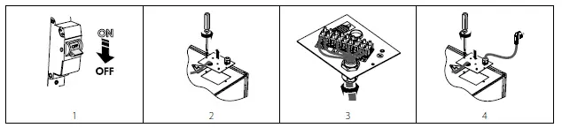
VKP(S), VKPI, VKPF, VKPFI 400*200, 500*250, 500*300, 600*300, 600*350
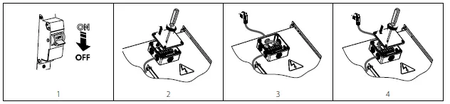
VKPF, VKPFI 700*400, 800*500, 900*500, 1000*500
ASYNCHRONOUS ELECTRIC MOTOR STARTING METHODS
There are several methods for starting asynchronous squirrel-cage electric motors.
The most common methods are: direct-on-line (DOL), with a soft starter (SS) or with a frequency converter (FC).
Direct-on-line starting
In case of direct-on-line starting (i.e. by connecting the motor to the electric mains with a simple line contactor), the motor starting time significantly increases due to high inertia of the impeller, which, in turn, results in high in-rush starting currents in the circuit. These currents of long duration may cause voltage slumps (especially if the feed line section falls short of the requirements), which may affect load operation.
The in-rush current consumed by an electric motor in case of DOL starting is 5-8 times larger than the rated value (or even 10-14 times larger in some rare instances). It should be noted that the torque developed by the motor also significantly exceeds the rated value. Upon energisation the motor operates as a transformer with a squirrel-cage secondary winding formed by the rotor cage with a very low resistance.
The rotor develops high induced current causing a rush of current in the feed line.
The startup torque during starting averages 0.5-1.5 of the rated torque value.
Despite such advantages as simple construction, high startup current, quick start and low cost, direct-on-line systems are suitable only in the following cases:
- the motor power is low compared to the mains power which limits the adverse effect of the rush of current
- the driven mechanism does not require gradual speed build-up or is equipped with a damping device to smooth out the inrush
- the high startup torque has no adverse effects on the operation of the driven mechanism
Soft start. SS starting.
A soft starter gradually increases the voltage supplied to the motor – from the initial to the rated value. This starting system can be used to meet the following goals:
- limit the motor current
- regulate the torque
Regulation by limiting the current sets the maximum in-rush current equal to 300-400 % (or 250 % in some rare instances) of the rated current and reduces torque characteristics. This type of regulation is especially suited for turbomachinery such as centrifugal pumps and fans.
Regulation by variation of torque optimizes the torque during startup and reduces in-rush current in the circuit. These conditions are suitable for mechanisms with constant load resistance.
This type of soft starting may differ in the implementation pattern:
- motor start
- motor start and stop
- device bridging at the end of start sequence
- start and stop of several motors in stage circuits
Soft start. FC starting.
During the starting the FC raises the frequency from 0 Hz to the electrical mains frequency (50 or 60 Hz). As the frequency is increased gradually, the motor can be assumed to operate at its rated speed for a given frequency value. Furthermore, on the assumption that the motor runs at its rated speed the nominal torque should be immediately available whereas the current will be approximately equal to the rated value.
This starting system is used for speed control and regulation and can be used in the following cases:
- start with high-inertia load
- start with high load and limited-capacity power supply source
- optimization of electric power consumption depending on turbomachinery speed The aforementioned starting system can be used for all types of mechanisms.
Problems associated with DOL starting
The problems caused by DOL starting may be divided into two groups:
- An abrupt start causes mechanical shock, jolts in the mechanism, shock removal of free play etc.
- A heavy start cannot be completed.
Let us review three variations of a heavy start:
- The feed line performance is barely sufficient or insufficient to maintain the induced current.
Typical symptoms: Upon starting the circuit breakers at the system input are tripped; the lights, certain relays and contactors go off, and the supply generator shuts down.
Solution: In the best-case scenario an SS device may help reduce the in-rush current to 250 % of the motor rated current. If this is insufficient, an FC is necessary. - The motor cannot start the mechanism with DOL starting.
Typical symptoms: The motor fails to turn or “freezes” at certain speed which is maintained until actuation of the protection suite. Solution: This problem may not be solved with an SS device. The motor develops insufficient shaft torque. However, this problem can be addressed by using an FC, but each case may be different. - The motor spins up the mechanism with authority, but fails to reach the rated rotation speed.
Typical symptoms: The input automatic circuit breaker is tripped during spin-up. This often happens with heavy-weight fans with a considerable rotation speed.
Solution: Such problems may be addressed with an SS device, but not with 100 % certainty. The closer the motor speed to the rated value during the actuation of the protective equipment, the higher the chances of success. The use of an FC in this case helps solve the problem fundamentally.
Standard switching equipment (automatic circuit breakers, contactors and motor starters) is not designed to withstand prolonged overloads normally causing the fan to shut down automatically DOL starting that continues for a long period of time.
Using switching equipment with a higher maximum current rating renders the electric motor protection system less sensitive. As a result the switching equipment will not be able to detect motor overload in time due to a high current sensing threshold. Such problems as mentioned above can only be addressed by utilizing a soft starter or a frequency converter to start the fan.
MAKE SURE THAT THE FAN IMPELLER ROTATES IN THE DIRECTION MARKED BY THE ARROW ON THE FAN CASING.
IF NECESSARY, CHANGE THE IMPELLER ROTATION DIRECTION BY ALTERING THE PHASE SEQUENCE ON THE ELECTRIC MOTOR TERMINALS.
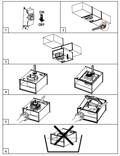
TECHNICAL MAINTENANCE
DISCONNECT THE UNIT FROM POWER SUPPLY BEFORE ANY MAINTENANCE OPERATIONS!
MAKE SURE THE UNIT IS DISCONNECTED FROM POWER MAINS BEFORE REMOVING THE PROTECTION
Prior to performing any technical maintenance and repair disconnect the fan from the electric mains and wait until its rotating parts come to a complete stop.
The technical maintenance includes periodic cleaning of the surfaces from accumulated dust and dirt.
Use a soft brush or compressed air to remove dust from metal surfaces of the fan. Use a vacuum cleaner to remove dust from the sound insulating surface.
The impeller blades require thorough cleaning once in 6 months.
Detach air ducts from the fan before starting maintenance works.
Clean the impeller blades with a soft cloth wetted in mild water detergent solution. Avoid liquid dripping on the motor.
Wipe the fan surfaces dry after cleaning.
While cleaning the fan make sure the balance counterweights are not shifted and the impeller is not misaligned.
TROUBLESHOOTING
| Problem | Possible reasons | Troubleshooting |
| The fan does not run. | No power supply. | Check the automatic circuit breaker. Check the electric connections. |
| Noisy operation. | Impeller imbalance. | Clean the impeller. |
STORAGE AND TRANSPORTATION REGULATIONS
- Store the unit in the manufacturer’s original packaging box in a dry closed ventilated premise with temperature range from +5 ˚C to +40 ˚C and relative humidity up to 70 %.
- Storage environment must not contain aggressive vapors and chemical mixtures provoking corrosion, insulation, and sealing deformation.
- Use suitable hoist machinery for handling and storage operations to prevent possible damage to the unit.
- Follow the handling requirements applicable for the particular type of cargo.
- The unit can be carried in the original packaging by any mode of transport provided proper protection against precipitation and mechanical damage. The unit must be transported only in the working position.
- Avoid sharp blows, scratches, or rough handling during loading and unloading.
- Prior to the initial power-up after transportation at low temperatures, allow the unit to warm up at operating temperature for at least
3- 4 hours.
MANUFACTURER’S WARRANTY
The product is in compliance with EU norms and standards on low voltage guidelines and electromagnetic compatibility. We hereby declare that the product complies with the provisions of Electromagnetic Compatibility (EMC) Directive 2014/30/EU of the European Parliament and of the Council, Low Voltage Directive (LVD) 2014/35/EU of the European Parliament and of the Council and CE-marking Council Directive 93/68/EEC. This certificate is issued following test carried out on samples of the product referred to above.
The manufacturer hereby warrants normal operation of the unit for 24 months after the retail sale date provided the user’s observance of the transportation, storage, installation, and operation regulations. Should any malfunctions occur in the course of the unit operation through the Manufacturer’s fault during the guaranteed period of operation, the user is entitled to get all the faults eliminated by the manufacturer by means of warranty repair at the factory free of charge. The warranty repair includes work specific to elimination of faults in the unit operation to ensure its intended use by the user within the guaranteed period of operation. The faults are eliminated by means of replacement or repair of the unit components or a specific part of such unit component.
The warranty repair does not include:
- routine technical maintenance
- unit installation/dismantling
- unit setup
To benefit from warranty repair, the user must provide the unit, the user’s manual with the purchase date stamp, and the payment paperwork certifying the purchase. The unit model must comply with the one stated in the user’s manual. Contact the Seller for warranty service.
The manufacturer’s warranty does not apply to the following cases:
- User’s failure to submit the unit with the entire delivery package as stated in the user’s manual including submission with missing component parts previously dismounted by the user.
- Mismatch of the unit model and the brand name with the information stated on the unit packaging and in the user’s manual.
- User’s failure to ensure timely technical maintenance of the unit.
- External damage to the unit casing (excluding external modifications as required for installation) and internal components caused by the user.
- Redesign or engineering changes to the unit.
- Replacement and use of any assemblies, parts and components not approved by the manufacturer.
- Unit misuse.
- Violation of the unit installation regulations by the user.
- Violation of the unit control regulations by the user.
- Unit connection to power mains with a voltage different from the one stated in the user’s manual.
- Unit breakdown due to voltage surges in power mains.
- Discretionary repair of the unit by the user.
- Unit repair by any persons without the manufacturer’s authorization.
- Expiration of the unit warranty period.
- Violation of the unit transportation regulations by the user.
- Violation of the unit storage regulations by the user.
- Wrongful actions against the unit committed by third parties.
- Unit breakdown due to circumstances of insuperable force (fire, flood, earthquake, war, hostilities of any kind, blockades).
- Missing seals if provided by the user’s manual.
- Failure to submit the user’s manual with the unit purchase date stamp.
- Missing payment paperwork certifying the unit purchase.
FOLLOWING THE REGULATIONS STIPULATED HEREIN WILL ENSURE A LONG AND TROUBLE-FREE OPERATION OF THE UNIT.
USER’S WARRANTY CLAIMS SHALL BE SUBJECT TO REVIEW ONLY UPON PRESENTATION OF THE UNIT, THE PAYMENT DOCUMENT AND THE USER’S MANUAL WITH THE PURCHASE DATE STAMP.


