Autonics DRW190837AE TR1D Series Independent Single Display PID Temperature Controllers
Thank you for choosing our Autonics product.
Read and understand the instruction manual and manual thoroughly before using the product. For your safety, read and follow the below safety considerations before using. For your safety, read and follow the considerations written in the instruction manual, other manuals and Autonics website. Keep this instruction manual in a place where you can find easily. The specifications, dimensions, etc are subject to change without notice for product improvement Some models may be discontinued without notice. Follow Autonics website for the latest information.
Safety Considerations
- Observe all ‘Safety Considerations’ for safe and proper operation to avoid hazards.
- symbol indicates caution due to special circumstances in which hazards may occur.
Warning:Failure to follow instructions may result in serious injury or death
- Fail-safe device must be installed when using the unit with machinery that may cause serious injury or substantial economic loss.(e.g. nuclear power control, medical equipment, ships, vehicles, railways, aircraft, combustion apparatus, safety equipment, crime/disaster prevention devices, etc.)
Failure to follow this instruction may result in personal injury, economic loss or fire. - Do not use the unit in the place where flammable/explosive/corrosive gas, high humidity, direct sunlight, radiant heat, vibration, impact or salinity may be present.
Failure to follow this instruction may result in explosion or fire. - Install the unit on DIN rail to use.
Failure to follow this instruction may result in electric shock. - Do not connect, repair, or inspect the unit while connected to a power source.
Failure to follow this instruction may result in fire or electric shock. - Check ‘Connections’ before wiring.
Failure to follow this instruction may result in fire. - Do not disassemble or modify the unit.
Failure to follow this instruction may result in fire or electric shock.
Caution Failure to follow instructions may result in injury or product damage
- When connecting the power input and relay output, use AWG 20 (0.50 mm2) cable or over, and tighten the terminal screw with a tightening torque of 0.74 to 0.90 N m.
When connecting the sensor input and communication cable without dedicated cable, use AWG 28 to 16 cable and tighten the terminal screw with a tightening torque of 0.74 to 0.90 N m.
Failure to follow this instruction may result in fire or malfunction due to contact failure. - Use the unit within the rated specifications.
Failure to follow this instruction may result in fire or product damage - Use a dry cloth to clean the unit, and do not use water or organic solvent. Failure to follow this instruction may result in fire or electric shock.
- Keep the product away from metal chip, dust, and wire residue which flow into the unit.
Failure to follow this instruction may result in fire or product damage.
Cautions during Use
- Follow instructions in ‘Cautions during Use’. Otherwise, it may cause unexpected accidents.
- Check the polarity of the terminals before wiring the temperature sensor. For RTD temperature sensor, wire it as 3-wire type, using cables in same thickness and length. For thermocouple (CT) temperature sensor, use the designated compensation wire for extending wire.
- Keep away from high voltage lines or power lines to prevent inductive noise .In case of installing power line and input signal line closely, use line filter or varistor at power line and shielded wire at input signal line.Do not use near the equipment which generates strong magnetic force or high frequency noise.
- Do not apply excessive power when connecting or disconnecting the connectors of the product.
- Install a power switch or circuit breaker in the easily accessible place for supplying or disconnecting the power.
- Do not use the unit for other purpose (e.g. voltmeter, ammeter), but temperature controller.
- When changing the input sensor, turn off the power first before changing. After changing the input sensor, modify the value of the corresponding parameter.
- Do not overlapping communication line and power line. Use twisted pair wire for communication line and connect ferrite bead at each end of line to reduce the effect of external noise.
- Make a required space around the unit for radiation of heat. For accurate temperature measurement, warm up the unit over 20 min after turning on the power.
- Make sure that power supply voltage reaches to the rated voltage within 2 sec after supplying power.
- Do not wire to terminals which are not used.
- This unit may be used in the following environments.
- Indoors (in the environment condition rated in ‘Specifications’)
- Altitude Max. 2,000 m
- Pollution degree 2
- Installation category II
Ordering Information
| Model | Control output1 | Control output2 | Option output | Additional function |
| TR1D-14RN 01) | Relay | – | – | – |
| TR1D-14RR | Relay | Relay ↔ Alarm | – | CT input, Dual alarm output 02) |
| TR1D-R4RR | Relay | Relay ↔ Alarm | Transmission | CT input, Dual alarm output 02) |
| TR1D-T4RR | Relay | Relay ↔ Alarm | Communication | CT input, Dual alarm output02) |
| TR1D-14CN 01) | Current/SSR | – | – | – |
| TR1D-14CC | Current/SSR | Current/SSR ↔ Transmission | – | CT input |
| TR1D-R4CC | Current/SSR | Current/SSR ↔ Transmission | Transmission | CT input, Dual transmission output |
| TR1D-T4CC | Current/SSR | Current/SSR ↔ Transmission | Communication | CT input |
- The model does not support terminal for the control output 2 is not available to use heating&cooling control and alarm outputs at the same time.
- It is not possible to use dual alarm output and heating&cooling control at the same time.
Product Components
- Product
- Instruction manual
Manual
For proper use of the product, refer to the manuals and be sure to follow the safety considerations in the manuals.
Download the manuals from the Autonics website.
Software
Download the installation file and the manuals from the Autonics website.
DAQMaster
DAQMaster is comprehensive device management program. It is available for parameter setting, monitoring.
Unit Descriptions
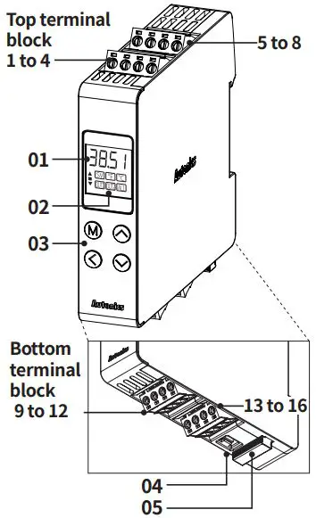
- PV / SV display part (Red)
RUN mode: Displays PV (Present value) and SV (Setting value).
Parameter: Displays name and setting value of parameters. - Indicator
Indicator ON contition SV SV display OUT□ Control output□ ON AL1 AL1 alarm output ON ■ The difference between PV and SV is less than 2℃
▲/▼ The difference between PV and SV is greater than 2℃
℃ or ℉ ‘2-2 Temperature unit’ parameter setting - Control key
[M]: MODE key
[◀ ] / [▲] / [▼]: Setting value control key - PC loader port
Communication converter (Sold separately) connection - Bracket handle
Use to mount and detach the DIN rail.
Specifications
| Series | TR1D Series | |
| Power supply | 100 – 240 VACᜠ 50/60 Hz | |
| Allowable voltage range | 90 to 110% of rated voltage | |
| Power consumption | ≤ 8 VA | |
| Sampling period | 50, 100, 250 ms | |
| Input specification | Refer to ‘Input Type and Using Range’. | |
| Option input | CT input | • 0.0-50.0 A (primary current measurement range) • CT ratio: 1/1,000, • Measurement accuracy: ±5% F.S. ±1digit |
| Control output | relay | 250 VACᜠ 3 A 1a |
| SSR | 12 VDCᜡ ±3 V, ≤ 20 mA | |
| Current | DC 4-20 mA or DC 0-20 mA (parameter), Load: ≤ 500 Ω | |
| Option output | Alarm | AL1, AL2: 250 VACᜠ 3 A 1a |
| Transmission | DC4-20 mA (Load resistance: ≤ 500 Ω, Output accuracy: ±0.3% F.S.) | |
| RS485 comm. | Modbus RTU / ASCII | |
| Display type | 7 segment (red), 4-digit | |
| Control type | ON/OFF, P, PI, PD, PID Control | |
| Hysteresis | Control output: 1 to 100 ℃/℉ (0.1 to 100.0 ℃/℉) Alarm output: 1 to 100 ℃/℉ (0.1 to 50.0 ℃/℉) | |
| Proportional band (P) | 0.1 to 999.9 ℃ | |
| Integral time (I) | 0 to 9,999 sec | |
| Derivative time (D) | 0 to 9,999 sec | |
| Control cycle (T) | Relay output: 0.5 to 120.0 sec, SSR drive output: 0.5 to 120.0 sec | |
| Manual reset | 0.0 to 100.0% | |
| Dielectric strength | Between the power part and the case: 3,000 VACᜠ 50/60 Hz for 1 min | |
| Vibration | 0.75 mm amplitude at frequency of 5 to 55Hz (for 1 min) in each X, Y, Z direction for 2 hours | |
| Relay life cycle | Mechanical | OUT1/2, AL1/2: ≥ 5,000,000 operations |
| Electrical | OUT1/2, AL1/2: ≥ 100,000 operations (resistance load: 250 VACᜠ 5 A) | |
| Insulation resistance | ≥ 100 MΩ (500 VDCᜡ megger) | |
| Insulation type | Double insulation or reinforced insulation (dielectric strength between the power part and the case: 3 kV) | |
| Noise immunity | Square shaped noise (pulse width: 1 ㎲) by noise simulator ±2 kV R-phase, S-phase | |
| Memory retention | ≈ 10 years (non-volatile semiconductor memory type) | |
| Ambient temperature | -10 to 50 ℃, storage: -20 to 60 ℃ (no freezing or condensation) | |
| Ambient humidity | 35 to 85%RH, storage: 35 to 85%RH (no freezing or condensation) | |
| Approval | ᜢ | |
| Unit weight (packaged) | ≈ 123.5 g (≈ 194.5 g) | |
Communication Interface
| Communication protocol | Modbus RTU / ASCII |
| Application standard | EIA RS485 compliance with |
| Maximum connection | 31 units (address: 01 to 127) |
| Synchronous method | Asynchronous |
| Communication method | Two-wire half duplex |
| Communication effective range | ≤ 800 m |
| Communication speed | 4,800 – 9,600 (default) – 19,200 – 38,400 – 57,600 – 115,200 bps (parameter) |
| Response time | 5 to 99 ms (default: 20 ms) |
| Start bit | 1 bit (fixed) |
| Data bit | 8 bit (fixed) |
| Parity bit | None (default), Odd, Even |
| Stop bit | 1 bit, 2 bit (default) |
- It is recommended to use Autonics communication Please use twisted pair wire, which is suitable for
Input Type and Using Range
- The setting range of some parameters is limited when using the decimal point display.
| Input type | Decimal point | Display Method | Using range(℃) | Using range(℉) | |
|
Thermo -couple | K (CA) | 1 | KCaH | -50 to 1,200 | -58 to 2,192 |
| 0.1 | KCaL | -50.0 to 999.9 | -58.0 to 999.9 | ||
| J (IC) | 1 | JIcH | -30 to 800 | -22 to 1,472 | |
| 0.1 | JIcL | -30.0 to 800.0 | -22.0 to 999.9 | ||
| L (IC) | 1 | LIcH | -40 to 800 | -40 to 1,472 | |
| 0.1 | LIcL | -40.0 to 800.0 | -40.0 to 999.9 | ||
| T (CC) | 1 | TCcH | -50 to 400 | -58 to 752 | |
| 0.1 | TCcL | -50.0 to 400.0 | -58.0 to 752.0 | ||
| R (PR) | 1 | RPR | 0 to 1,700 | 32 to 3,092 | |
| S (PR) | 1 | 5PR | 0 to 1,700 | 32 to 3,092 | |
|
RTD | DPt100 Ω | 1 | DPtH | -100 to 400 | -148 to 752 |
| 0.1 | DPtL | -100.0 to 400.0 | -148.0 to 752.0 | ||
| CU50 Ω | 1 | CUsH | -50 to 200 | -58 to 392 | |
| 0.1 | CU%L | -50.0 to 200.0 | -58.0 to 392.0 | ||
| Nickel120 Ω | 1 | NI12 | -80 to 260 | -112 to 500 | |
Display accuracy
- The setting range of some parameters is limited when using the decimal point display.
| Input type | Using temperature | Measurement accuracy |
|
Thermocouple RTD |
At room temperature (23℃±5 ℃) | (PV ±0.3% or ±1 ℃ higher one) ±1-digit • Thermocouple R (PR), S (PR) below 200 ℃: (PV ±0.5% or ±3 ℃ higher one) ±1-digit, Over 200 ℃: (PV ±0.5% or ±2 ℃ higher one) ±1-digit, • Thermocouple L (IC), RTD Cu50 Ω: (PV ±0.5% or ±2 ℃ higher one) ±1-digit |
| Out of room temperature range | (PV ±0.5% or ±2 ℃ higher one) ±1-digit • Thermocouple R (PR) , S (PR): (±1.0% or ±5 ℃ higher one) ±1-digit • Thermocouple L (IC), RTD Cu50 Ω: (PV ±0.5% or ±3 ℃ higher one) ± 1-digit |
- When multiple products (or more) are mounted without separation, ±1°C is added to all accuracy.
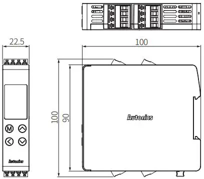
Dimensions
- Unit: mm, For the detailed drawings, follow the Autonics website.

Connections
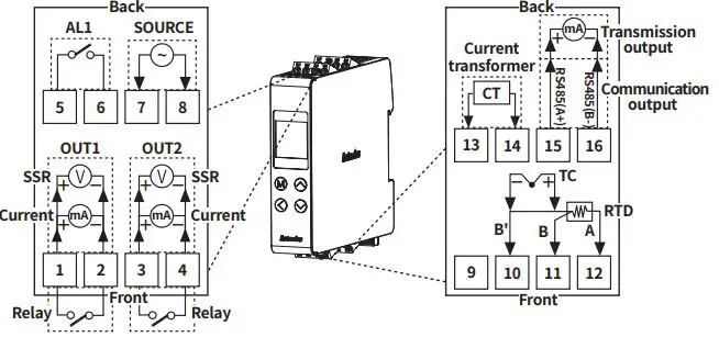
Terminal support by model
| Terminal No. | 1 | 2 | 3 | 4 | 5 | 6 | 7 | 8 | 9 | 10 | 11 | 12 | 13 | 14 | 15 | 16 |
| Function
Model | Control output 1 | Control output 2 | Alarm output | Power | – | Temperature sensor input | CT input | Option output | ||||||||
| TR1D-14RN | Relay | – | Relay | ○ | – | TC | – | – | – | – | – | |||||
| RTD | ||||||||||||||||
| TR1D-14RR | Relay | Relay | Relay | ○ | – | TC | – | ○ | – | – | ||||||
| RTD | ||||||||||||||||
| TR1D-R4RR | Relay | Relay | Relay | ○ | – | TC | – | ○ | Trans -mission | |||||||
| RTD | ||||||||||||||||
| TR1D-T4RR | Relay | Relay | Relay | ○ | – | TC | – | ○ | Communi -cation | |||||||
| RTD | ||||||||||||||||
| TR1D-14CN | Current | – | Relay | ○ | – | TC | – | – | – | – | – | |||||
| SSR | RTD | |||||||||||||||
| TR1D-14CC | Current | Current | Relay | ○ | – | TC | – | ○ | – | – | ||||||
| SSR | SSR | RTD | ||||||||||||||
| TR1D-R4CC | Current | Current | Relay | ○ | – | TC | – | ○ | Trans -mission | |||||||
| SSR | SSR | RTD | ||||||||||||||
| TR1D-T4CC | Current | Current | Relay | ○ | – | TC | – | ○ | Communi -cation | |||||||
| SSR | SSR | RTD | ||||||||||||||
Initial Display When Power is ON
When power is supplied, after all display will flash for a while, series and model name are displayed sequentially. After input sensor type will flash twice, enter into RUN mode.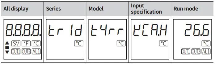
Errors
| Display | Description | Troubleshooting |
| OPEN | Flashes if input sensor is disconnected or sensor is not connected. | Check input sensor status. |
| HHHH | Flashes when PV is higher than input range. | When input is within the rated temperature range, this display disappears. |
| LLLL | Flashes when PV is lower than input range. |
Installation Method
Mounting on DIN rail
- Mount the metal part with a spanner so that a large force is not applied to the body.
Install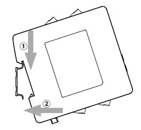
- Hang the top of backside holder to 35 mm width DIN rail.
- Press the unit in the direction of the arrow until there is clicking sound.
Uninstall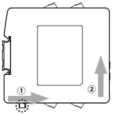
- Pull the bracket handle on the bottom of the unit in the direction of the arrow.
- Lift the unit up while pulling the handle bracket to remove.
Attaching and Dettaching a Terminal Unit
Detaching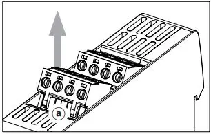
Lift the lower part of the terminal unit ⓐ upwards by using a tool (e.g. flat-head driver).
Attaching
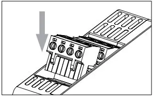
Press the terminal unit downwards to insert.
- When disconnecting terminal unit and wiring, refer to ‘Connections’ to attach to right position. Failure to follow this instruction may result in fire product damage or malfunction.
Mode Setting
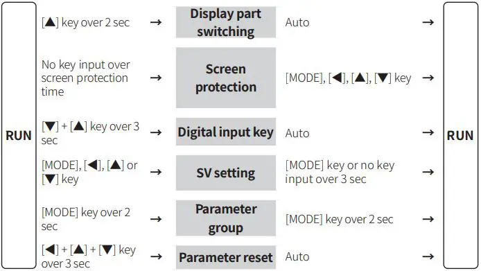
Parameter Setting
- Some parameters are activated/deactivated depending on the model or setting of other parameters. Refer to the descriptions of each item.
- Select group by [▲], [▼] key and press [MODE] key to parameter setting mode in parameter group setting mode.
- [MODE] key: Move to next item after saving / Return to upper level with save (≥ 2 sec) ] key: Move digits / Return to the upper level without saving (≥ 2 sec) / Return to RUN mode without saving (≥ 3 sec) ], [▼] key: Select parameter / Change setting value • Return to the upper level without saving when there is no key input for more than 30 seconds.
- The range in parentheses ‘( )’ is the setting range when the set value of the ‘input specification’ parameter is used with one decimal point.
- Recommended parameter setting sequence: Parameter 2 group → Parameter 1 group → SV setting mode
Parameter 1 group
| Parameter | Display | Default | Setting range | Condition |
|
1-1 Lock |
LOCK |
OFF | OFF LOC1: Lock parameter 2 group LOC2: Lock parameter 1, 2 group LOC3: Lock parameter 1, 2 group + SV setting lock • It is possible to check the value only in lock mode. |
– |
| Heater 1-2 current monitoring | CT-A | – | [CT input model] 0.0 to 50.0 A | 2-10/11 Control output 1/2: SSR |
| 1-3 Auto tuning | AT | OFF | OFF, ON: Execution | 2-9 Control type: PID |
| 1-4 AL1 alarm temperature | AL1 | 1250 | Deviation alarm: -F.S. to F.S. ℃/℉ Absolute value alarm: Within input specification • Changing the ‘2-16/19 AL1/2 alarm operation’ and ‘2-17/20 AL1/2 alarm option’ will automatically reset the value to the maximum or minimum that will not be output. | 2-16/19 AL1/2 alarm operation: AM1 to AM6, HBA |
| 1-5 AL2 alarm temperature | AL2 | 1250 | ||
| Heating 1-6 proportional band | H-P | 10 | 0.1 to 999.9 ℃/℉ | – |
| 1-7 Heating integral time | H-I | 240 | 0 (OFF) to 9999 sec | – |
| Heating 1-8 derivative time | H-D | 49 | 0 (OFF) to 9999 sec | – |
| Cooling 1-9 proportional band | C-P | 10 | 0.1 to 9999 ℃/℉ | – |
| 1-10 Cooling integral time | C-I | 240 | 0 (OFF) to 9999 sec | – |
| Cooling 1-11 derivative time | C-D | 49 | 0 (OFF) to 9999 sec | – |
| 1-12 Dead band 01) |
DB |
0 | -Proportional band to +Proportional band ℃/℉ | 2-9 Control type: P.P, P.ON, ON.P |
| -999 to 999 (-199.9 to 999.9) ℃/℉ | 2-9 Control type: ON.ON | |||
| 1-13 Manual reset | REST | 50 | 0.0 to 100.0% | 1-7/10 Heating/ Cooling integral time: 0 |
| 1-14 Heating hysteresis | hHYS | 2 | 1 to 100 (0.1 to 100.0) ℃/℉ | 2-9 Control type: ONOF & 2-8 Control output mode 02) |
| 1-15 Heating OFF offset | hOST | 0 | 0 to 100 (0.0 to 100.0) ℃/℉ | |
| 1-16 Cooling hysteresis | cHYS | 2 | 1 to 100 (0.1 to 100.0) ℃/℉ | |
| 1-17 Cooling OFF offset | cOST | 0 | 0 to 100 (0.0 to 100.0) ℃/℉ |
- When set to the + value, the dead band is formed based on SV and does not control any control.
When set to the – value, the overlap band is formed based on SV, perform the heating and cooling control at the same time. - Parameter display following to the setting value of ‘2-8 Control output mode’
HEAT: ‘1-14 & 15 Heating hysteresis & OFF offset’
COOL: ‘1-16 & 17 Cooling hysteresis & OFF offset’
H-C: ‘1-14 & 15 Heating hysteresis & OFF offset’, ‘1-16 & 17 Cooling hysteresis & OFF offset’
| Parameter | Display | Default | Setting range | Condition | |
| 2-1 | Input specification | IN-T | KCaH | Refer to ‘Input Type and Using Range’ | – |
| 2-2 | Temperature unit | UNIT | ?C | ℃, ℉ | – |
| 2-3 | Sampling period | SPlT | 50 | 50, 100, 250 ms | – |
| 2-4 | Input correction | IN-B | 0 | -999 to 999 (-199.9 to 999.9) ℃/℉ | – |
| 2-5 | Input digital filter | MAvF | )1 | 0.1 to 120.0 sec | – |
| 2-6 | SV low limit value | L-SV | -50 | Within 2-1 Input specification L-SV ≤ H-SV – 1-digit ℃/℉ H-SV ≥ L-SV + 1-digit ℃/℉ | – |
| 2-7 | SV high limit value | H-SV | 1200 | – | |
| 2-8 | Control output mode | O-FT | H-C | HEAT: Heating, COOL: Cooling, H-C: Heating&Cooling | – |
| 2-9 | Control type | C-MD | pP | PID, ONOF: ON/OFF, P.P: PID-PID*, ON.ON: ON/OFF-ON/OFF*, P.ON: PID-ON/OFF*, ON.P: ON/OFF-PID* | * 2-8 Control output mode: H-C |
| 2-10 | Control output 1 | OUT1 | CURR | [Current/SSR output model] SSR, CURR: Current | – |
| 2-11 | Control output 2 | OUT2 | |||
| 2-12 | Control output 1 range | O!MA | 4-20 | 4-20, 0-20 mA | 2-10/11 Control output 1/2: CURR |
| 2-13 | Control output 2 range | O@MA | |||
| 2-14 | Heating control cycle | H-T | 2)0 | [Relay output model] 0.5 to 120.0 sec | – |
| @0 | [Current/SSR output model] 0.5 to 120.0 sec | 2-10/11 Control output 1/2: SSR | |||
| 2-15 | Cooling control cycle | C-T | 2)0 | [Relay output model] 0.5 to 120.0 sec | – |
| @0 | [Current/SSR output model] 0.5 to 120.0 sec | 2-10/11 Control output 1/2: SSR | |||
|
2-16 |
AL1 alarm operation |
AL-1 |
AM!A □□□.■ | □□□ AM0: OFF AM1: Deviation high limit alarm AM2: Deviation low limit alarm AM3: Deviation high, low limit alarm AM4: Deviation high, low limit reserve alarm AM5: Absolute value high limit alarm AM6: Absolute value low limit alarm SBA: Sensor break alarm LBA: Loop break alarm HBA: Heater break alarm |
– |
|
2-17 |
AL1 alarm option | ■ A: Standard alarm, B: Alarm latch, C: Standby sequence 1, D: Alarm latch and sequence 1, E: Standby sequence 2, F: Alarm latch and sequence 2 • Enter to option setting: Press [◀] key in 2-16 AL-1 alarm operation. |
– | ||
| 2-18 | AL1 Hysteresis | A!HY | 1 | 1 to 100 (0.1 to 50.0) ℃/℉ | 2-16/17 AL1/2 Alarm operation: AM1 to AM6 or HBA |
| 2-19 | AL2 alarm operation | AL-2 | AM!A | [Dual alarm output model] Same as ‘2-16/17 AL1 alarm operation/ option’ | 2-8 Control output mode: HEAT or COOL |
| 2-20 | AL2 alarm option | ||||
| 2-21 | AL2 hysteresis | A@HY | 1 | [Dual alarm output model] 1 to 100 (0.1 to 50.0) ℃/℉ | 2-16/17 AL1/2 Alarm operation: AM1 to AM6 or HBA |
| 2-22 | LBA time 01) | LBaT | 0 | 0 to 9999 sec or auto setting 02) | 2-16/17 AL1/2 alarm operation: LBA |
| 2-23 | LBA band | LBaB | 2 | 0 to 999 (0.0 to 999.9) ℃/℉ or Auto setting 03) | |
| 2-24 | Transmission output1 mode | AoM1 | PV | [Transmission output model] PV, SV, H-MV: Heating MV), C-MV: Cooling MV |
– |
| 2-25 | Transmission output1 low limit | FS!L | -50 | [Transmission output model] Refer to ‘Input Type and Using Range’ | |
| 2-26 | Transmission output1 high limit | FS!H | 1200 | ||
| 2-27 | Transmission output2 mode | AoM2 | PV | [Dual transmission output model] PV, SV, H-MV: Heating MV, C-MV: Cooling MV |
2-8 Control output mode: HEAT or COOL |
| 2-28 | Transmission output2 low limit | FS!L | -50 | [Dual transmission output model] Refer to ‘Input Type and Using Range’ | |
| 2-29 | Transmission output2 high limit | FS!H | 1200 | ||
| 2-30 | Digital input key | DI-K | STOP | STOP: Stop control output, ALRE: Alarm reset, AT: Auto tuning execution, OFF | – |
|
2-31 |
Sensor error, MV |
ErMV |
0 | 0.0 (OFF) to 100.0 (ON) | 2-8 Control output mode: HEAT or COOL |
| -100 (Cooling ON) to 0.0 (OFF) to 100 (Heating ON) | 2-8 Control output mode: H-C | ||||
| 2-32 | Screen protection | DSP | OFF | OFF, 1, 30, 60 min | – |
| 2-33 | Comm. protocol | PRCL | RTU | RTU: Modbus RTU, ASCI: Modbus ASCII | – |
| 2-34 | Comm. address | ADRS | 1 | 1 to 99 | – |
| 2-35 | Comm. speed | BPS | 96 | 48, 96, 192, 384, 576, 1152 (×100) bps | – |
| 2-36 | Comm. parity bit | PRTY | NONE | None, Even, Odd | – |
| 2-37 | Comm. stop bit | STP | 2 | 1, 2 bit | – |
| 2-38 | Response time | RSwT | 20 | 5 to 99 ms | – |
| 2-39 | Comm. write | COMW | EnA | EN.A: Enable, DIS.A: Disable | – |
| 2-40 | Parameter reset | INIT | NO | YES, NO | – |
- Initialization condition of LBA time (alarm output status)
Alarm reset, change ‘2-8 Control output mode’ (standard alarm: OFF, alarm latch: OFF), Change ‘2-4 Input correction’ or SV (Standard alarm: latch, alarm latch: latch), Error status: OPEN, HHHH, LLLL (Standard alarm: Immediately ON, alarm latch: Immediately ON) Stop condition of LBA operation (Alarm output status) Set ‘2-22/23 LBA time/band: 0’ (standard alarm: OFF, alarm latch: latch) Stop control output, execute auto tuning (standard alarm: OFF, alarm latch: latch), If ‘2-1 Input specification’ is changed, the settings are initialized. - After auto tuning, the range is set as twice of the integral time automatically. If the previous setting value is outside of the range automatically set, it is set to the nearest Max. or Min. value of the range.
- After auto tuning, the range is set as 10% of the proportion band automatically. If the previous setting value is outside of the range automatically set, it is set to the nearest Max. or Min. value of the range.
18, Bansong-ro 513Beon-gil, Haeundae-gu, Busan, Republic of Korea, 48002
www.autonics.com | +82-51-519-3232 | [email protected]


