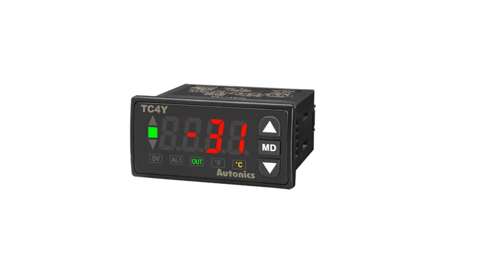
Autonics TC Series TC4Y-N4R Single Display PID Temperature Controllers Instruction Manual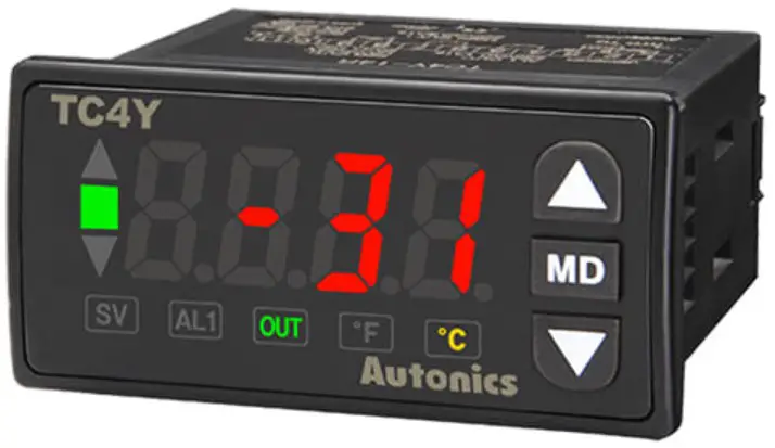
Read and understand the instruction manual and manual thoroughly before using the product.
For your safety,read and follow the below safety considerations before using.
For your safety,read and follow the considerations written in the instruction manual, other manuals andAutonics website.
Keep this instruction manual in a place where you can find easily.
The specifications, dimensions, etc are subjectto change without notice for product improvement Some models may be discontinued without notice.
Safety Considerations
- Observe all ‘Safety Considerations’ for safe and proper operation to avoid hazards.
- ᜠsymbol indicates caution due to special circumstances in which hazards may occur.
![]() Warning Failure to follow instructions may resulting serious injury or death
Warning Failure to follow instructions may resulting serious injury or death
- Fail-safe device must be installed when using the unit with machinery that may cause serious injury or substantial economic loss.(e.g. nuclear power control, medical equipment, ships, vehicles, railways, aircraft, combustion apparatus, safety equipment, crime/disaster prevention devices, etc.)
Failure to follow this instruction may result in personal injury, economic loss or fire. - Do not use the unit in the place where flammable/explosive/corrosive gas, high humidity, direct sunlight, radiant heat, vibration, impact or salinity may be present.
Failure to follow this instruction may resultin explosion orfire. - Install on a device panelto use.
Failure to follow this instruction may resultin fire or electric shock. - Do not connect, repair, or inspect the unit while connected to a power source.
Failure to follow this instruction may resultin fire or electric shock. - Check ‘Connections’ before wiring.
Failure to followthis instruction may resultin fire. - Do not disassemble or modify the unit.
Failure to follow this instruction may resulting fire or electric shock.
![]() Caution Failure to follow instructions may resultin injury or product damage
Caution Failure to follow instructions may resultin injury or product damage
- When connecting the powerinput and relay output, use AWG 20 (0.50 mm2 ) cable or over and tighten the terminal screw with a tightening torque of 0.74 to 0.90 N m. When connecting the sensor input and communication cable without dedicated cable, use AWG 28 to 16 cable and tightenthe terminal screw wit a tightening torque of 0.74 to 0.90 N m.
Failure to followthis instruction may resultin fire or malfunction due to contact failure. - Use the unit within the rated specifications.
Failure to followthis instruction may resultin fire or product damage - Use a dry cloth to clean the unit, and do not use water or organic solvent.
Failure to follow this instruction may resultin fire or electric shock. - Keep the product away from metal chip, dust, and wire residue which flow into the unit.
Failure to follow this instruction may resultin fire or product damage.
Cautions during Use
- Follow instructions in ‘Cautions during Use’. Otherwise, it may cause unexpected
accidents. - Check the polarity of the terminals before wiring the temperature sensor. For RTD
temperature sensor ,wire it as 3-wire type, using cables in same thickness and length. For thermocouple (TC)temperature sensor, use the designated compensation wire for
extending wire. - Keep away from high voltage lines or power lines to prevent inductive noise. In case installing power line and input signal line closely, use line filter or visitor at power line and shielded wire at input signal line. Do not use near the equipment which generates strong magnetic force or high frequency noise.
- Install a power switch or circuit breaker in the easily accessible place for supplying or disconnecting the power.
- Do not use the unit for other purpose (e.g. voltmeter, ammeter), but temperature controller.
- When changing the input sensor, turn off the power first before changing. After changing the input sensor, modify the value of the corresponding parameter.
- 24 VACᜠ, 24-48 VDCᜠ power supply should be insulated and limited voltage/current or Class 2, SELV power supply device.
- Make a required space around the unitforradiation of heat. For accurate temperature measurement, warm up the unit over 20 min afterburning on the power.
- Make sure that power supply voltage reaches to the rated voltage within 2 sec after supplying power.
- Do not wire to terminals which are not used.
- This unit may be used in the following environments.
- Indoors (in the environment condition rated in ‘Specifications’)
- AltitudeMax. 2,000 m
- Pollution degree 2
- Installation category II
Ordering Information
This is only for reference, the actual product does not support all combinations. For selecting the specified model, follow the Autonics website .
- Size
S: DIN W 48× H 48 mm
SP: DIN W 48× H 48 mm (11 pin plug type)
Y: DIN W 72× H 36 mm
M: DIN W 72× H 72 mm
H: DIN W 48× H 96 mm
W: DIN W 96× H 48 mm
L: DIN W 96× H 96 mm - Alarm output
N:No alarm- 1 alarm
- 2 alarm
- Power supply
2: 24VACᜠ 50/60Hz, 24-48 VDCᜠ
4: 100-240 VACᜠ50/60 Hz - Control output
N: Indicator – without control output
R:Relay + SSR drive
Product Components
- Product
- Bracket
- Instruction manual
Sold Separately
- 11 pin socket: PG-11, PS-11 (N)
- Terminal protection cover: RSA / RMA / RHA / RLA Cover
Specifications
| Series | TC4□-□2□ | TC4□-□4□ | |
| Power supply | 24 VACᜠ 50/60 Hz ±10%24-48 VDCᜡ ±10% | 100 – 240 VACᜠ 50/60 Hz ±10% | |
| Power consumption | AC: ≤ 5 VA, DC: ≤ 3 W | ≤ 5 VA | |
| Sampling period | 100 ms | ||
| Input specification | Refer to ‘Input Type and Using Range’. | ||
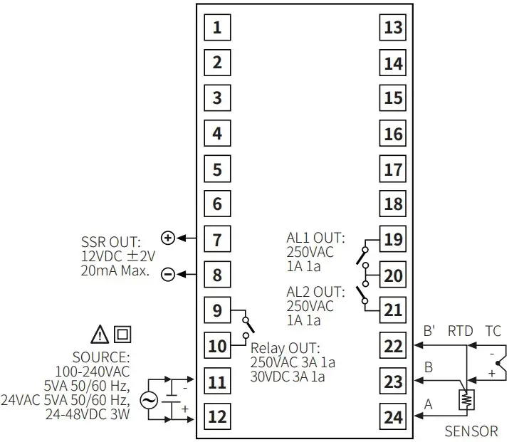
| Control output | Relay | 250 VACᜠ 3 A, 30 VDCᜡ 3 A, 1a | |
| SSR | 12 VDCᜡ±2 V, ≤ 20 mA | ||
| Alarm output | 250 VACᜠ 1 A 1a | ||
| Display type | 7 Segment (red, green, yellow), LED type | ||
| Control type | Heating,Cooling | ON/OFF, P, PI, PD, PID Control | |
| Hysteresis | 1 to 100 (0.1 to 50.0) ℃/℉ | ||
| Proportional band (P) | 0.1 to 999.9 ℃/℉ | ||
| Integral time (I) | 0 to 9,999 sec | ||
| Derivative time (D) | 0 to 9,999 sec | ||
| Control cycle (T) | 0.5 to 120.0 sec | ||
| Manual reset | 0.0 to 100.0% | ||
| Relay life cycle | Mechanical | OUT1/2, AL1/2: ≥ 5,000,000 operations | |
| Electrical | OUT1/2: ≥ 200,000 operations (load resistance: 250 VACᜠ 3A) AL1/2: ≥ 300,000 operations (load resistance: 250 VACᜠ 1 A ) | ||
| Dielectric strength | Between input terminal and power terminal: 1,000 VACᜠ 50/60 Hz for 1 min | Between input terminal and power terminal: 2,000 VACᜠ 50/60 Hz 1 min | |
| Vibration | 0.75 mm amplitude at frequency 5 to 55Hz (for 1 min) in each X, Y, Zdirection for 2 hours | ||
| Insulation resistance | ≥ 100 MΩ (500 VDCᜡ megger) | ||
| Noise immunity | Square shaped noise (pulse width: 1 ㎲) by noise simulator ±2 kV R-phase, S-phase | ||
| Memory retention | ≈ 10 years (non-volatile semiconductor memory type) | ||
| Ambient temperature | -10 to 50 ℃, storage: -20 to 60 ℃ (no freezing or condensation) | ||
| Ambient humidity | 35 to 85%RH, storage: 35 to 85%RH (no freezing or condensation) | ||
| Insulation type | Mark: ▱, double or reinforced insulation (dielectric strength between the measuring input part and the power part: 1 kV) | Mark: ▱, double or reinforced insulation (dielectric strength between the measuring input part and the power part: 2 kV) | |
| Approval | ᜢ ᜧ ᜫ | ||
Unit weight (packaged) |
|
| |
|
| ||
|
| ||
| |||
Input Type and Using Range
| Input type | Decimalpoint | Display | Using range (℃) | Using range (℉) | |||||
| Thermo-couple | K (CA) | 1 | KC | -50 | to | 1,200 | -58 | to | 2,192 |
| J (IC) | 1 | JIC | -30 | to | 500 | -22 | to | 932 | |
| L (IC) | 1 | LIC | -40 | to | 800 | -40 | to | 1,472 | |
RTD | Cu50 Ω | 1 | CU | -50 | to | 200 | -58 | to | 392 |
| 0.1 | CU L | -50.0 | to | 200.0 | -58.0 | to | 392.0 | ||
| DPt100 Ω | 1 | DPt | -100 | to | 400 | -148 | to | 752 | |
| 0.1 | DPtL | -100.0 | to | 400.0 | -148.0 | to | 752.0 | ||
Display accuracy
| Input type | Using temperature | Display accuracy |
| Thermo-coupleRTD | At room temperature(23℃ ±5 ℃) | (PV ±0.5% or ±1 ℃ higher one) ±1-digit
|
| Out of room temperature range | (PV ±0.5% or ±2 ℃ higher one) ±1-digit
|
- In case of TC4SP Series, ±1℃ will be added.
- If the input specification is set to ‘decimal point 0.1’ display, add ±1℃ by accuracy standard.
Unit Descriptions
- Temperature Display part (Red)
- Run mode: Displays PV (Present value).
- Setting mode :Displays parameter name,
- indicator
- Input key
| Display | Name |
| [MODE] | Mode key |
| [◀], [▼], [▲] | Setting value control key |
| Display | Name | Description |
| ▲■▼ | Deviation | Displays PV deviation based on SV (Setting value) by LED.▲: ON when deviation is over +2 ℃■: ON when deviation is within ±2 ℃▼: ON when deviation is under -2 ℃Flashes during auto tuning every 1 sec |
| SV | Setting value | Turns ON when SV is displayed on temperature display part. |
| ℃, ℉ | Temperature unit | Displays selected unit (parameter). |
| AL1/2 | Alarm output | Turns ON when each alarm output is ON. |
| OUT | Control output | Turns ON when control output is ON.• CYCLE/PHASE control of SSR drive output: Turns ON when MV is over 3.0%. (only for AC power model) |
Errors
| Display | Description | Troubleshooting |
| OPEN | Flashes when input sensor is disconnected or sensor is not connected. | Check input sensor status. |
| Flashes when PV is higher than input range. | When input is within the rated inputrange, this display disappears. | |
| LLLL | Flashes when PV is lower than input range. |
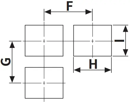
Dimensions
- Unit: mm, Forthe detailed drawings, follow the Autonics website.
- Below is based on TC4S Series.


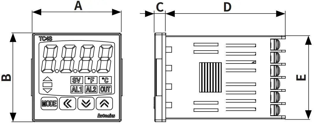
| Series | Body | Panel cut-out | |||||||
| A | B | C | D | E | F | G | H | I | |
| TC4S | 48 | 48 | 6 | 64.5 | 45 | ≥ 65 | ≥ 65 | 45+0.60 | 45+0.60 |
| TC4SP | 48 | 48 | 6 | 72.2 | 45 | ≥ 65 | ≥ 65 | 45+0.60 | 45+0.60 |
| TC4Y | 72 | 36 | 7 | 77 | 30 | ≥ 91 | ≥ 40 | 68+0.70 | 31.5+0.50 |
| TC4W | 96 | 48 | 6 | 64.5 | 44.7 | ≥ 115 | ≥ 65 | 92+0.80 | 45+0.60 |
| TC4M | 72 | 72 | 6 | 64.5 | 67.5 | ≥ 90 | ≥ 90 | 68+0.70 | 68+0.70 |
| TC4H | 48 | 96 | 6 | 64.5 | 91.5 | ≥ 65 | ≥ 115 | 45+0.60 | 92+0.80 |
| TC4L | 96 | 96 | 6 | 64.5 | 91.5 | ≥ 115 | ≥ 115 | 92+0.80 | 92+0.80 |
Bracket 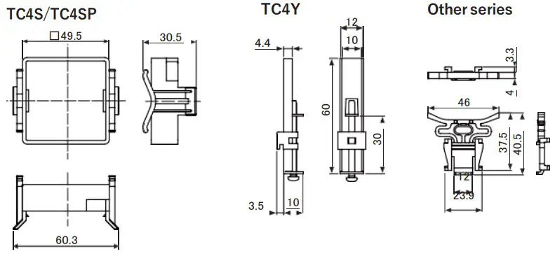
Installation Method
TC4S
Flathead screwdriver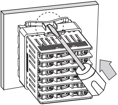
TC4Y
Crosshead screwdriver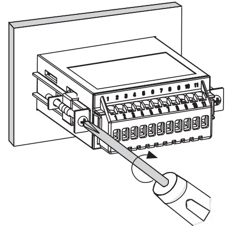
Other series
Flathead screwdriver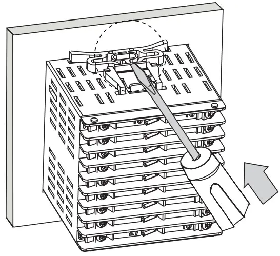
Mount the product to panel with bracket, push ditto arrow direction by using screw driver.
In case of TC4Y Series, fasten the bolts.
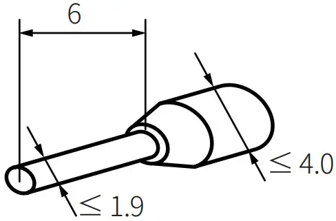
Crimp Terminal Specifications
- Unit: mm, Use the crimp terminal of follow shape
Wire ferrule
Fork crimp terminal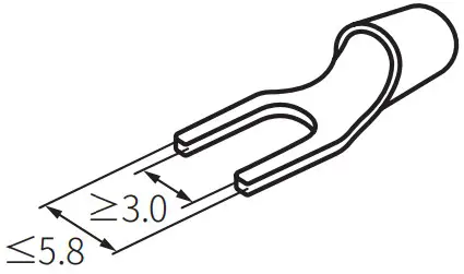
Round crimp terminal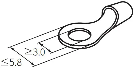
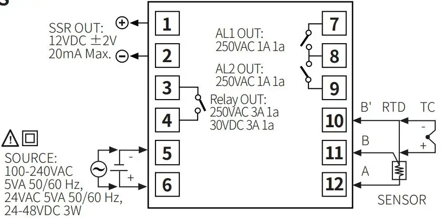
Connections
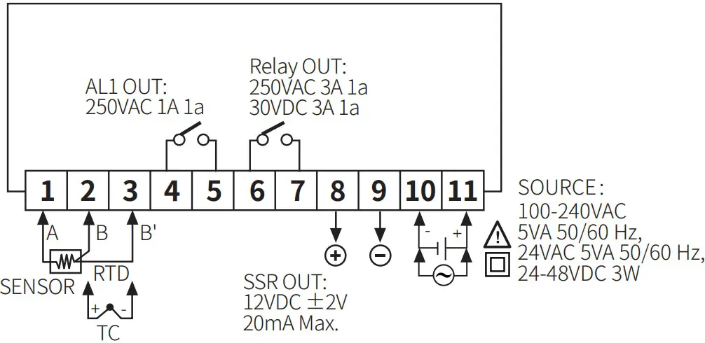
- TC4S

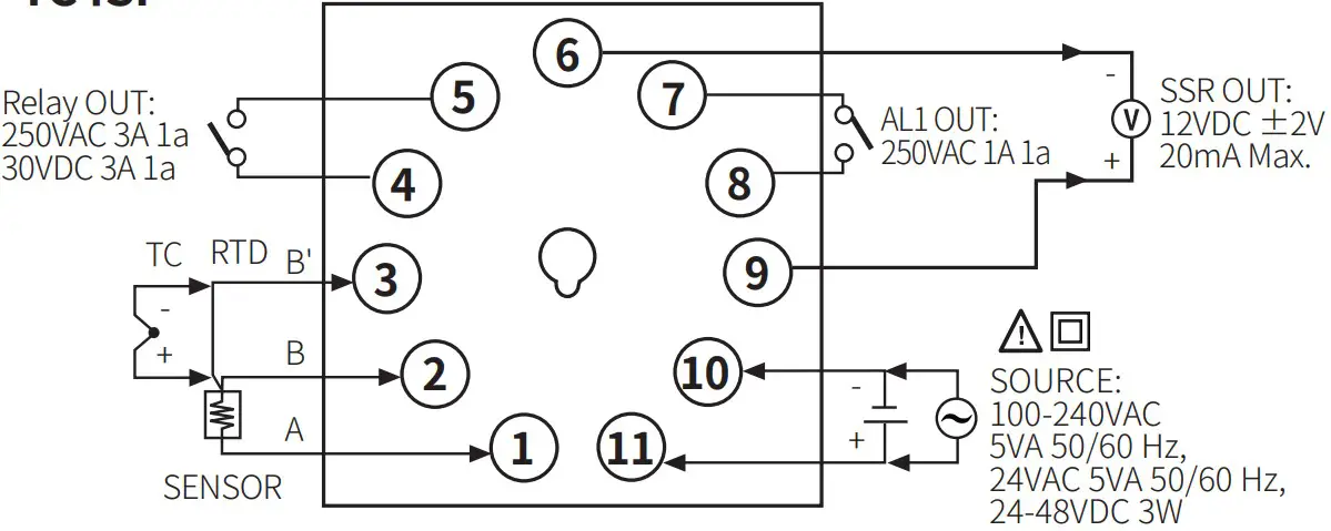
- TC4SP

- TC4Y

- TC4W

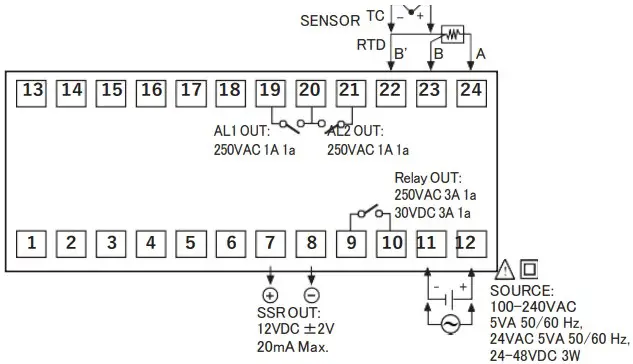
- TC4M

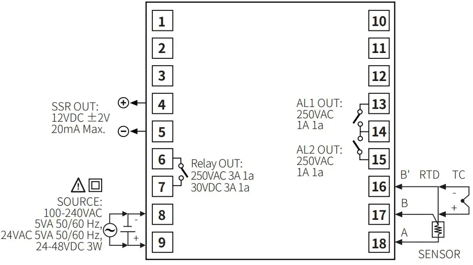
- TC4H/L

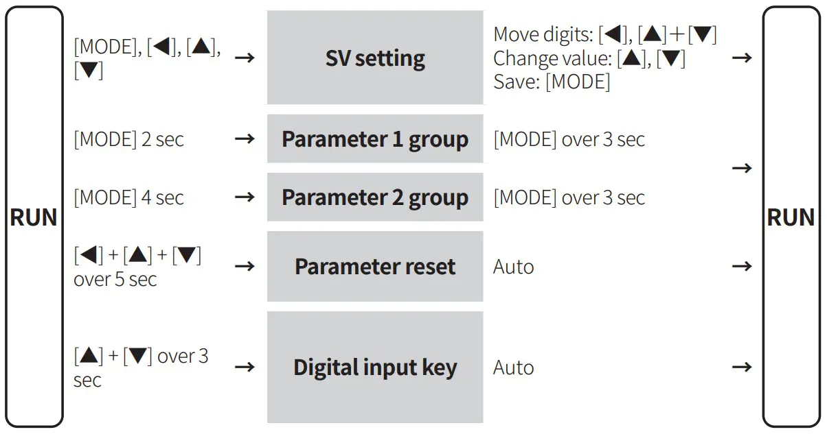
Mode Setting
Parameter Setting
- Some parameters are activated/deactivated depending on the model or setting of other parameters. Refer to the description of each item.
- The setting range in parentheses is for using the decimal point display in the input specification.
- If there is no key input for more than 30 seconds in each parameter, it returns to RUN mode.
- When pressing the [MODE] key within 1 second after returning to the operation mode from the parameter group, it will enter the parameter group before returning.
- [MODE] key: Saves the current parameter setting value and moves to the next parameter. [◀] key: Moves the column when changing the set value [▲], [▼] keys: Selects the parameter / Changes the set value
- Recommended parameter setting sequence: Parameter 2 group → Parameter 1 group → SV setting mode ■ Parameter 1 group
- Only appears at control output model
| Parameter | Display | Default | Setting range | Condition | |
| 1-1 | AL1 alarm temperature | L | 250 | Deviation alarm: -F.S. to F.S. ℃/℉ Absolute value alarm: Within input range | 2-12/14AL1/2 alarm operation: AM1 to AM6 |
| 1-2 | AL2 alarm temperature | L2 | 250 | [2 alarm output model]Same as 1-1 AL1 alarm temperature | |
| 1-3 | Auto tuning | T | OFF | OFF: Stop, ON: Execution | 2-8 Control type: PID |
| 1-4 | Proportionalband | P | 0 )0 | 0.1 to 999.9 ℃/℉ | |
| 1-5 | Integral time | I | 0000 | 0 (OFF) to 9999 sec | |
| 1-6 | Derivativetime | D | 0000 | 0 (OFF) to 9999 sec | |
| 1-7 | Manual reset | REST | 05)0 | 0.0 to 100.0% | 2-8 Control type: PID & 1-5 Integraltime: 0 |
| 1-8 | Hysteresis | YS | 002 | 1 to 100 (0.1 to 50.0) ℃/℉ | 2-8 Controltype: ONOF |
Parameter 2 group
In case of indicator model, only appears 2-1 to 4 / 2-19 parameters
| Parameter | Display | Default | Setting range | Condition | ||
| 2-1 | Inputspecification 01) | IN-T | KC | Refer to ‘Input Type and Using Range’. | – | |
| 2-2 | Temperature unit 01) | UNIT | ?C | ℃, ℉ | – | |
| 2-3 | Input correction | IN-B | 0000 | -999 to 999 (-199.9 to 999.9) ℃/℉ | – | |
| 2-4 | Input digitalfilter | M F | 00) | 0.1 to 120.0 sec | – | |
| 2-5 | SV low limit 02) | L-SV | -050 | Within 2-1 Input specification: Using range,L-SV ≤ H-SV – 1-digit ℃/℉ H-SV ≥ L-SV + 1-digit ℃/℉ | – | |
| 2-6 | SV high limit 02) | -SV | 200 | – | ||
| 2-7 | Control output mode | O-FT | E T | HEAT: Heating, COOL: Cooling | – | |
| 2-8 | Control type 03) | C-MD | PID | PID, ONOF: ON/OFF | – | |
| 2-9 | Control output | OUT | RLY | RLY: relay, SSR | – | |
| 2-10 | SSR drive output type | SSrM | STND | [AC voltage model]STND: standard, CYCL: cycle, PHAS:phase | 2-9 Controloutput: SSR | |
| 2-11 | Control cycle | T | 02)0 | 0.5 to 120.0 sec | 2-9 Controloutput: RLY2-10 SSR drive output type: STND | |
| 00 0 | 2-9 Controloutput: SSR2-10 SSR drive output type: STND | |||||
| 2-12 | AL1 alarm operation 04) | L- | M!□□□.■ | □□□ AM0: OffAM1: Deviation high limit alarm AM2: Deviation low limit alarmAM3: Deviation high, low limit alarm AM4: Deviation high, low reverse alarm AM5: Absolute value high limit alarm AM6: Absolute value low limit alarm SBA: Sensor break alarmLBA: Loop break alarm (LBA) | – | |
| 2-13 | AL1 alarm option | ■A: Standard alarmC: Standby sequence 1E: Standbysequence 2 | B: Alarm latchD: Alarm latch and standby sequence 1F: Alarm latch andstandby sequence 2 | – | ||
| • Enter to option setting: Press [◀] keyin 2-12 AL-1 alarm operation. | ||||||
| 2-14 | AL2 alarm operation 04) | L-2 | M | [2 alarm output model]Same as 2-12/13 AL1 alarm operation/option | – | |
| 2-15 | AL2 alarm option | |||||
| 2-16 | Alarm output hysteresis | YS | 000 | 1 to 100 (0.1 to 50.0) ℃/℉ | 2-12/14AL1/2 alarm operation: AM1 to 6 | |
| 2-17 | LBA time | LBaT | 0000 | 0 (OFF) to 9,999 sec or auto (auto tunning) | 2-12/14AL1/2 alarm operation: LBA | |
| 2-18 | LBA band | LBaB | 002 | 0 (OFF) to 999 (0.0 to 999.9) ℃/℉ orauto (auto tunning) | 2-12/14AL1/2 alarm operation: LBA & 2-17 LBAtime: > 0 | |
| 2-19 | Digital inputkey | DI-K | STOP | STOP: Stop control output, AL.RE: Alarm reset, AT*: Auto tuning execution, OFF | *2-8 Control type: PID | |
| 2-20 | Sensor error MV | ErMV | 00)0 | 0.0: OFF, 100.0: ON | 2-8 Controltype: ONOF | |
| 0.0 to 100.0% | 2-8 Control type: PID | |||||
| 2-21 | Lock | LOC | OFF | OFFLOC1: Parameter 2 group lock LOC2: Parameter 1/2 Group lockLOC3: Parameter 1/2 Group, SV settinglock | – | |
| [Indicator model]OFFLOC1: Parameter 2 group lock | ||||||
| Parameter | Display | Default | Setting range | Condition | ||
| 2-1 | Inputspecification 01) | IN-T | KC | Refer to ‘Input Type and Using Range’. | – | |
| 2-2 | Temperature unit 01) | UNIT | ?C | ℃, ℉ | – | |
| 2-3 | Input correction | IN-B | 0000 | -999 to 999 (-199.9 to 999.9) ℃/℉ | – | |
| 2-4 | Input digitalfilter | M F | 00) | 0.1 to 120.0 sec | – | |
| 2-5 | SV low limit 02) | L-SV | -050 | Within 2-1 Input specification: Using range,L-SV ≤ H-SV – 1-digit ℃/℉ H-SV ≥ L-SV + 1-digit ℃/℉ | – | |
| 2-6 | SV high limit 02) | -SV | 200 | – | ||
| 2-7 | Control output mode | O-FT | E T | HEAT: Heating, COOL: Cooling | – | |
| 2-8 | Control type 03) | C-MD | PID | PID, ONOF: ON/OFF | – | |
| 2-9 | Control output | OUT | RLY | RLY: relay, SSR | – | |
| 2-10 | SSR drive output type | SSrM | STND | [AC voltage model]STND: standard, CYCL: cycle, PHAS:phase | 2-9 Controloutput: SSR | |
| 2-11 | Control cycle | T | 02)0 | 0.5 to 120.0 sec | 2-11Controloutput: RLY2-12 SSR drive output type: STND | |
| 00 0 | 2-11Controloutput: SSR2-12 SSR drive output type: STND | |||||
| 2-12 | AL1 alarm operation 04) | L- | M!□□□.■ | □□□ AM0: OffAM1: Deviation high limit alarm AM2: Deviation low limit alarmAM3: Deviation high, low limit alarm AM4: Deviation high, low reverse alarm AM5: Absolute value high limit alarm AM6: Absolute value low limit alarm SBA: Sensor break alarmLBA: Loop break alarm (LBA) | – | |
| 2-13 | AL1 alarm option | ■A: Standard alarmC: Standby sequence 1E: Standbysequence 2 | B: Alarm latchD: Alarm latch and standby sequence 1F: Alarm latch andstandby sequence 2 | – | ||
| • Enter to option setting: Press [◀] keyin 2-12 AL-1 alarm operation. | ||||||
| 2-14 | AL2 alarm operation 04) | L-2 | M | [2 alarm output model]Same as 2-12/13 AL1 alarm operation/option | – | |
| 2-15 | AL2 alarm option | |||||
| 2-16 | Alarm output hysteresis | YS | 000 | 1 to 100 (0.1 to 50.0) ℃/℉ | 2-12/14AL1/2 alarm operation: AM1 to 6 | |
| 2-17 | LBA time | LBaT | 0000 | 0 (OFF) to 9,999 sec or auto (auto tunning) | 2-12/14AL1/2 alarm operation: LBA | |
| 2-18 | LBA band | LBaB | 002 | 0 (OFF) to 999 (0.0 to 999.9) ℃/℉ orauto (auto tunning) | 2-12/14AL1/2 alarm operation: LBA & 2-17 LBAtime: > 0 | |
| 2-19 | Digital inputkey | DI-K | STOP | STOP: Stop control output, AL.RE: Alarm reset, AT*: Auto tuning execution, OFF | *2-8 Control type: PID | |
| 2-20 | Sensor error MV | ErMV | 00)0 | 0.0: OFF, 100.0: ON | 2-8 Controltype: ONOF | |
| 0.0 to 100.0% | 2-8 Control type: PID | |||||
| 2-21 | Lock | LOC | OFF | OFFLOC1: Parameter 2 group lock LOC2: Parameter 1/2 Group lockLOC3: Parameter 1/2 Group, SV settinglock | ||
| [Indicator model] OFF LOC1: Parameter 2 group lock | ||||||
- Below parameters are initialized when the setting value is changed
- Parameter 1 group:AL1/2 alarm temperature
- Parameter 2 group: Input correction, SV high/low limit, Alarm output hysteresis, Blaine, Laban
- SV setting mode: SV
- IASIS lower/higher than low/high limit when the value is changed, SVis changed to the low/high limit value. If 2-1 Input specification is changed,the value is changed to Min./Max. value of Input specification.
- When changing the value from PID to ONOF, each value of following parameter is changed. 2-19 Digital input key: OFF, 2-20 Sensor error MV: 0.0 (When setting value is lower than 100.0)
- 1-1/2 AL1, AL2 alarm temperature setting values are initialized when the setting value is changed.
18, Bansong-ro 513Beon-gil, Haeundae-gu, Busan, Republic of Korea, 48002
www.autonics.com | +82-2-2048-1577 | [email protected]


