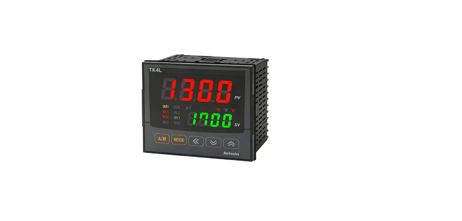
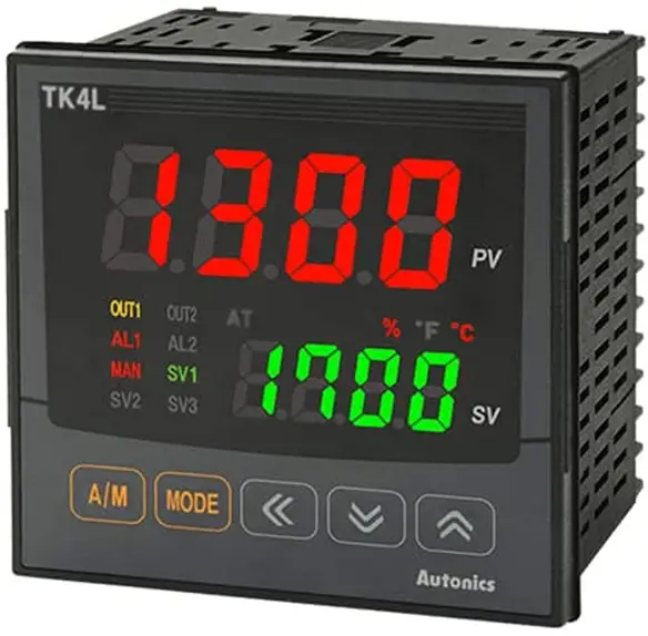
Autonics TK Series Simultaneous Heating and Cooling Output PID Temperature Controllers
Thank you for choosing our Autonics product
Read and understand the instruction manual and manual thoroughly before using the product. For your safety, read and follow the below safety considerations before using. For your safety, read and follow the considerations written in the instruction manual, other manuals and Autonics website. Keep this instruction manual in a place where you can find easily. The specifications, dimensions, etc are subject to change without notice for product improvement Some models may be discontinued without notice. Follow Autonics website for the latest information.
Product Information
The TK Series Simultaneous Heating & Cooling Output PIDTemperature Controllers are devices used for controlling temperature in different applications. They come with fail-safe features that ensure the safety of users and prevent damage to equipment.
Main Features
- Simultaneous heating and cooling output
- PID control algorithm for accurate temperature control
- Different control output options to suit specific applications
- Supports multiple functions including alarm, transmission output, and RS485 communication
- Rated for indoor use in environments that meet specified conditions
Safety Considerations
Before using this product, it is important to consider the following safety precautions:
- Install a fail-safe device when using the unit with machinery that may cause serious injury or substantial economic loss.
- Avoid using the unit in places where flammable, explosive, corrosive gas, high humidity, direct sunlight, radiant heat, vibration, impact or salinity may be present.
- Install the unit on a device panel to use and avoid connecting, repairing or inspecting the unit while connected to a power source.
- Check connections before wiring and avoid disassembling or modifying the unit.
Product Usage Instructions
Follow these instructions to use the TK Series Simultaneous
Heating & Cooling Output PID Temperature Controllers:
- Ensure that you have installed a fail-safe device if you are using the unit with machinery that may cause serious injury or substantial economic loss.
- Choose a suitable location indoors that meets the environment conditions specified in the product manual.
- Install the unit on a device panel before use.
- Check connections before wiring and use the recommended cable sizes specified in the product manual. Tighten terminal screws to the recommended torque specifications.
- Use the controller within the rated specifications to avoid damage or malfunction.
- Use a dry cloth to clean the unit and avoid using water or organic solvents that may cause fire or electric shock.
- Avoid exposing the product to metal chips, dust, and wire residue that may flow into the unit, causing damage or fire.
Ordering Information
The TK Series Simultaneous Heating & Cooling Output PID Temperature Controllers come in different models with varying options for input/output, function, power supply, and control output. For more information and to select a suitable model, you can visit the Autonics website.
Safety Considerations
- Observe all ‘Safety Considerations’ for safe and proper operation to avoid hazards.
- Symbol indicates caution due to special circumstances in which hazards may occur.
Warning: Failure to follow instructions may result in serious injury or death
- Fail-safe device must be installed when using the unit with machinery that may cause serious injury or substantial economic loss.(e.g. nuclear power control, medical equipment, ships, vehicles, railways, aircraft, combustion apparatus, safety equipment, crime/disaster prevention devices, etc.)
- Failure to follow this instruction may result in personal injury, economic loss or fire.
- Do not use the unit in the place where flammable/explosive/corrosive gas, high humidity, direct sunlight, radiant heat, vibration, impact or salinity may be present.
- Failure to follow this instruction may result in explosion or fire.
- Install on a device panel to use.
- Failure to follow this instruction may result in electric shock.
- Do not connect, repair, or inspect the unit while connected to a power source.
- Failure to follow this instruction may result in fire or electric shock.
- Check ‘Connections’ before wiring.
- Failure to follow this instruction may result in fire.
- Do not disassemble or modify the unit.
- Failure to follow this instruction may result in fire or electric shock.
Caution: Failure to follow instructions may result in injury or product damage.
- When connecting the power input and relay output, use AWG 20 (0.50 mm2) cable or over, and tighten the terminal screw with a tightening torque of 0.74 to 0.90 N m. When connecting the sensor input and communication cable without dedicated cable, use AWG 28 to 16 cable and tighten the terminal screw with a tightening torque of 0.74 to 0.90 N m.
- Failure to follow this instruction may result in fire or malfunction due to contact failure.
- Use the unit within the rated specifications.
- Failure to follow this instruction may result in fire or product damage
- Use a dry cloth to clean the unit, and do not use water or organic solvent.
- Failure to follow this instruction may result in fire or electric shock.
- Keep the product away from metal chip, dust, and wire residue which flow into the unit.
- Failure to follow this instruction may result in fire or product damage.
Cautions during Use
- Follow instructions in ‘Cautions during Use’. Otherwise, it may cause unexpected accidents.
- Check the polarity of the terminals before wiring the temperature sensor. For RTD temperature sensor, wire it as 3-wire type, using cables in same thickness and length. For thermocouple (TC) temperature sensor, use the designated compensation wire for extending wire.
- Keep away from high voltage lines or power lines to prevent inductive noise. In case installing power line and input signal line closely, use line filter or varistor at power line and shielded wire at input signal line. Do not use near the equipment which generates strong magnetic force or high frequency noise.
- Do not apply excessive power when connecting or disconnecting the connectors of the product.
- Install a power switch or circuit breaker in the easily accessible place for supplying or disconnecting the power.
- Do not use the unit for other purpose (e.g. voltmeter, ammeter), but temperature controller.
- When changing the input sensor, turn off the power first before changing. After changing the input sensor, modify the value of the corresponding parameter.
- 24 VAC
 , 24-48 VDC
 power supply should be insulated and limited voltage/current or Class 2, SELV power supply device.
 - Do not overlapping communication line and power line. Use twisted pair wire for communication line and connect ferrite bead at each end of line to reduce the effect of external noise.
- Make a required space around the unit for radiation of heat. For accurate temperature measurement, warm up the unit over 20 min after turning on the power.
- Make sure that power supply voltage reaches to the rated voltage within 2 sec after supplying power.
- Do not wire to terminals which are not used.
- This unit may be used in the following environments.
- Indoors (in the environment condition rated in ‘Specifications’)
- Altitude Max. 2,000 m
- Pollution degree 2
- Installation category II
Ordering Information
- This is only for reference, the actual product does not support all combinations.
- For selecting the specified model, follow the Autonics website.

- Size
- N: DIN W 48 × H 24 mm
- SP: DIN W 48 × H 48 mm (11 pin plug type)
- S: DIN W 48 × H 48 mm
- M: DIN W 72 × H 72 mm
- W: DIN W 96 × H 48 mm
- H: DIN W 48 × H 96 mm
- L: DIN W 96 × H 96 mm
- Option in/output
Size: N PN OUT2 Function 1 Normal type 01) Alarm 1 + CT input Heating & Cooling Alarm 2 2 Normal type Alarm 1 + Alarm 2 D Normal type Alarm 1 + Digital input 1/2 Heating & Cooling Digital input 1/2 R
Normal type Alarm 1+Transmission output
Heating & Cooling Transmission output T
Normal type Alarm output 1 + RS485 communication
Heating & Cooling RS485 communication Size: SP PN Function 1 Alarm 1 Size: S, M, W, H, L PN Function 1 Alarm 1 2 Alarm 1 + Alarm output 2 R Alarm 1 + Transmission output T Alarm 1 + RS485 communication A Alarm 1 + Alarm 2 + Transmission output B Alarm 1 + Alarm 2 + RS485 communication D Alarm 1 + Alarm 2 + Digital input 1/2 02) - Power supply
- 2: 24 VAC 50/60 Hz, 24-48 VDC
- 4: 100-240 VAC 50/60 Hz
- 2: 24 VAC
- OUT1 Control output
- R: Relay
- S: SSR drive
- C: Selectable current or SSR drive output
- OUT2 Control output
- N: Normal type
- [No OUT2 (Heating or Cooling)]
- R: Heating & Cooling type
- [Relay output] 03)
- C: Heating & Cooling type
- [Selectable current or SSR drive output] 04)
- N: Normal type
The CI input model ot TK4N can be selected only in the normal type model with alam Output 1. (except TK4sP)
- Only for TK4S-D, OUT2 output terminal is used as D-2 input terminal.
- When operating mode is heating or cooling control, OUT2 can be used as alarm output 3 (except TK4N).
- When operating mode is heating or cooling control, OUT2 can be used as transmission output 2.
Manual
- For proper use of the product, refer to the manuals and be sure to follow the safety considerations in the manuals.
- Download the manuals from the Autonics website.
Software
- Download the installation file and the manuals from the Autonics website.
DAQMaster
- DAQMaster is comprehensive device management program. It is available for parameter setting, monitoring.
Sold Separately
- 11 pin socket: PG-11, PS-11 (N)
- Current transformer (CT)
- Terminal protection cover: RSA / RMA / RHA / RLA Cover
- Communication converter: SCM Series
Specifications
| Series | TK4N | TK4SP | TK4S | TK4M | |
| Power supply | AC type | 100 – 240 VAC | |||
| AC/DC type | – | 24 VAC | |||
| Power consumption | AC type | ≤ 6 VA | ≤ 8 VA | ||
| AC/DC type | – | AC: ≤ 8 VA, DC ≤ 5W | |||
| Unit weight (packaged) | ≈ 70 g (≈ 140 g) | ≈ 85 g (≈ 130 g) | ≈ 105 g (≈ 150 g) | ≈ 140 g (≈ 210 g) | |
| Series | TK4W | TK4H | TK4L | |
| Power supply | AC type | 100 – 240 VAC | ||
| AC/DC type | 24 VAC | |||
| Power consumption | AC type | ≤ 8 VA | ||
| AC/DC type | AC: ≤ 8 VA, DC ≤ 5W | |||
| Unit weight (packaged) | ≈ 141 g (≈ 211 g) | ≈ 141 g (≈ 211 g) | ≈ 198 g (≈ 294 g) | |
| Sampling period | 50 ms | |
| Input specification | Refer to ‘Input Type and Using Range’ | |
|
Option input | CT input |
|
| Digital input |
| |
| Control output | Relay | 250 VAC |
| SSR | 11 VDC | |
| Current | DC 4-20 mA or DC 0-20 mA (parameter), Load resistance: ≤ 500 Ω | |
| Alarm output | Relay | AL1, AL2: 250 VAC
|
| Option output | Transmission | DC 4 – 20 mA (Load resistance: ≤ 500 Ω, Output accuracy: ±0.3% F.S.) |
| RS485 comm. | Modbus RTU | |
| Display type | 7 segment (red, green, yellow), LED type | |
| Control type | Heating, Cooling | ON/OFF, P, PI, PD, PID Control |
| Heating & Cooling | ||
| Hysteresis |
| |
| Proportional band (P) | 0.1 to 999.9 ℃/℉ (0.1 to 999.9%) | |
| Integral time (I) | 0 to 9,999 sec | |
| Derivative time (D) | 0 to 9,999 sec | |
| Control cycle (T) |
| |
| Manual reset | 0.0 to 100.0% | |
| Relay life cycle | Mechanical | OUT1/2: ≥ 5,000,000 operations AL1/2: ≥ 20,000,000 operations (TK4H/W/L: ≥ 5,000,000 operations) |
| Electrical | ≥ 100,000 operations | |
| Dielectric strength | Between power source terminal and input terminal: 2,000 VAC 50/60 Hz for 1 min | |
| Vibration | 0.75 mm amplitude at a frequency of 5 to 55 Hz (for 1 min) in each X, Y, Z direction for 2 hours | |
| Insulation resistance | ≥ 100 MΩ (500 VDC | |
| Noise immunity | ±2 kV square shaped noise by noise simulator (pulse width: 1 ㎲) R-phase, S-phase | |
| Memory retention | ≈ 10 years (non-volatile semiconductor memory type) | |
| Ambient temperature | -10 to 50 ℃, storage: -20 to 60 ℃ (no freezing or condensation) | |
| Ambient humidity | 35 to 85%RH, storage: 35 to 85%RH (no freezing or condensation) | |
| Protection structure | IP65 (Front panel, IEC standards) • TK4SP: IP50 (Front panel, IEC standards) | |
| Insulation type | Double insulation or reinforced insulation (mark: | |
| Accessory | Bracket, Terminal protection cover (TK4N) | |
| Approval | ||
Communication Interface
RS485
| Comm. protocol | Modbus RTU |
| Connection type | RS485 |
| Application standard | EIA RS485 compliance with |
| Maximum connection | 31 units (address: 01 to 99) |
| Synchronous method | Asynchronous |
| Comm. Method | Two-wire half duplex |
| Comm. effective range | ≤ 800 m |
| Comm. speed | 2,400 / 4,800 / 9,600 (default) / 19,200 / 38,400 bps (parameter) |
| Response time | 5 to 99 ms (default: 20 ms) |
| Start bit | 1 bit (fixed) |
| Data bit | 8 bit (fixed) |
| Parity bit | None (default), Odd, Even |
| Stop bit | 1 bit, 2 bit (default) |
| EEPROM life cycle | ≈ 1,000,000 operations (Erase / Write) |
Input Type and Using Range
The setting range of some parameters is limited when using the decimal point display.
| Input type | Decimal point | Display | Using range (℃) | Using range (℉) | |||||
|
Thermo -couple | K (CA) | 1 | KCaH | -200 | to | 1,350 | -328 | to | 2,463 |
| 0.1 | KCaL | -199.9 | to | 999.9 | -199.9 | to | 999.9 | ||
| J (IC) | 1 | JIcH | -200 | to | 800 | -328 | to | 1,472 | |
| 0.1 | JIcL | -199.9 | to | 800.0 | -199.9 | to | 999.9 | ||
| E (CR) | 1 | ECrH | -200 | to | 800 | -328 | to | 1,472 | |
| 0.1 | ECrL | -199.9 | to | 800.0 | -199.9 | to | 999.9 | ||
| T (CC) | 1 | TCcH | -200 | to | 400 | -328 | to | 752 | |
| 0.1 | TCcL | -199.9 | to | 400.0 | -199.9 | to | 752.0 | ||
| B (PR) | 1 | B PR | 0 | to | 1,800 | 32 | to | 3,272 | |
| R (PR) | 1 | R PR | 0 | to | 1,750 | 32 | to | 3,182 | |
| S (PR) | 1 | S PR | 0 | to | 1,750 | 32 | to | 3,182 | |
| N (NN) | 1 | N NN | -200 | to | 1,300 | -328 | to | 2,372 | |
| C (TT) 01) | 1 | C TT | 0 | to | 2,300 | 32 | to | 4,172 | |
| G (TT) 02) | 1 | G TT | 0 | to | 2,300 | 32 | to | 4,172 | |
| L (IC) | 1 | LIcH | -200 | to | 900 | -328 | to | 1,652 | |
| 0.1 | LIcL | -199.9 | to | 900.0 | -199.9 | to | 999.9 | ||
| U (CC) | 1 | UCcH | -200 | to | 400 | -328 | to | 752 | |
| 0.1 | UCcL | -199.9 | to | 400.0 | -199.9 | to | 752.0 | ||
| Platinel II | 1 | PLII | 0 | to | 1,390 | 32 | to | 2,534 | |
|
RTD | Cu50 Ω | 0.1 | CU 5 | -199.9 | to | 200.0 | -199.9 | to | 392.0 |
| Cu100 Ω | 0.1 | CU10 | -199.9 | to | 200.0 | -199.9 | to | 392.0 | |
| JPt100 Ω | 1 | JPtH | -200 | to | 650 | -328 | to | 1,202 | |
| 0.1 | JPtL | -199.9 | to | 650.0 | -199.9 | to | 999.9 | ||
| DPt50 Ω | 0.1 | DPT5 | -199.9 | to | 600.0 | -199.9 | to | 999.9 | |
| DPt100 Ω | 1 | DPtH | -200 | to | 650 | -328 | to | 1,202 | |
| 0.1 | DPtL | -199.9 | to | 650.0 | -199.9 | to | 999.9 | ||
| Nickel120 Ω | 1 | NI12 | -80 | to | 200 | -112 | to | 392 | |
|
Analog | 0 to 10 V | – | AV1 | 0 to | 10 V | ||||
| 0 to 5 V | – | AV2 | 0 to | 5 V | |||||
| 1 to 5 V | – | AV3 | 1 to | 5 V | |||||
| 0 to 100 mV | – | AMV1 | 0 to | 100 mV | |||||
| 0 to 20 mA | – | AMA1 | 0 to | 20 mA | |||||
| 4 to 20 mA | – | AMA2 | 4 to | 20 mA | |||||
- C (TT): Same as existing W5 (TT) type sensor
- G (TT): Same as existing W (TT) type sensor
- Permissible line resistance per line: ≤ 5 Ω
Display accuracy
| Input type | Using temperature | Display accuracy |
|
Thermo -couple RTD | At room temperature (23℃ ±5 ℃) | (PV ±0.3% or ±1 ℃ higher one) ±1-digit • Thermocouple K, J, T, N, E below -100 ℃ and L, U, PLII, RTD Cu50 Ω, DPt50 Ω: (PV ±0.3% or ±2 ℃ higher one) ±1-digit • Thermocouple C, G and R, S below 200 ℃: (PV ±0.3% or ±3 ℃ higher one) ±1-digit • Thermocouple B below 400 ℃: There is no accuracy standards |
| Out of room temperature range | (PV ±0.5% or ±2 ℃ higher one) ±1-digit • RTD Cu50 Ω, DPt50 Ω: (PV ±0.5% or ±3 ℃ higher one) ±1-digit • Thermocouple R, S, B, C, G: (PV ±0.5% or ±5 ℃ higher one) ±1-digit • Other sensors: ≤ ±5 ℃ (≤-100 ℃) | |
| Analog | At room temperature (23℃ ±5 ℃) | ±0.3% F.S. ±1-digit |
| Out of room temperature range | ±0.5% F.S. ±1-digit |
- In case of TK4SP Series, ±1 ℃ will be added to the degree standard.
Unit Descriptions
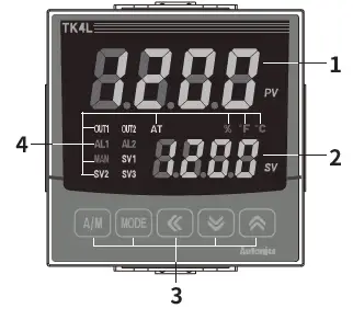
- PV display part (Red)
- Run mode: Displays PV (Present value).
- Setting mode: Displays parameter name.
- SV display part (Green)
- Run mode: Displays SV (Setting value).
- Setting mode: Displays parameter setting value.
- Input key
Display Name [A/M] Control switching key [MODE] Mode key [◀], [▼], [▲] Setting value control key - Indicator
Display Name Description ℃, %, ℉ Unit Displays selected unit (parameter) AT Auto tuning Flashes during auto tuning every 1 sec OUT1/2
Control output
Turns ON when the control output is ON SSR output (cycle/phase control)
MV over 5% ON
Current output
Manual control: 0% OFF, over ON
Auto control: below 2% OFF, over 3% ON
AL1/2 Alarm output Turns ON when the alarm output is ON MAN Manual control Turns ON during manual control SV1/2/3 Multi SV The SV indicator is ON which is currently displayed. (When using multi SV function) 
- PC loader port: For connecting communication converter (SCM series).
- For the details about old model, refer to the user manual. Download the manuals from the Autonics website.
Dimensions
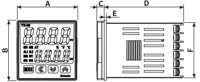
- Unit: mm, For the detailed drawings, follow the Autonics website.
- Below is based on TK4S Series.
Panel cut-out
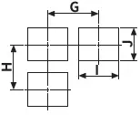
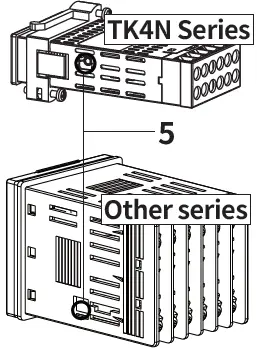
Bracket
TK4N /TK4S/SP /Other series
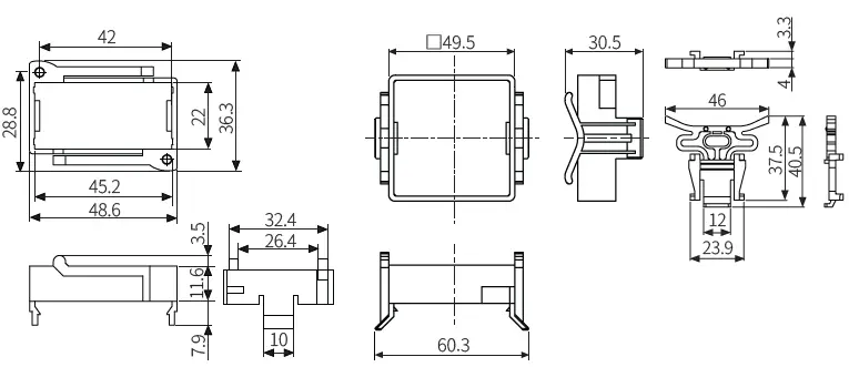
Terminal protection cover
TK4N
Installation Method
TK4N

- After mounting the product to panel with bracket, fasten the bolts by using screwdriver.
Other series
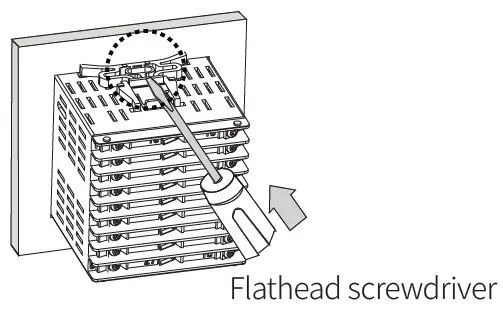
- Insert the unit into a panel, fasten the bracket by pushing with a flathead screwdriver.
Errors
| Display | Input | Description | Output | Troubleshooting |
| Temperature sensor | Flashes at 0.5 sec interval when input sensor is disconnected or sensor is not connected. | ‘Sensor error, MV’ parameter setting value | Check input sensor status. | |
| OPEN | ||||
| Analog | Flashes at 0.5 sec interval when input is over F.S. ±10%. | ‘Sensor error, MV’ parameter setting value | Check analog input status. | |
| Temperature sensor | Flashes at 0.5 sec intervals if the input value is above the input range. | Heating: 0%, Cooling: 100% | ||
| HHHH | ||||
| Analog | Flashes at 0.5 sec intervals if the input value is over 5 to 10% of high limit or low limit value. | Normal output | When input is within the rated input range, this display disappears. | |
| Temperature sensor | Flashes at 0.5 sec. intervals if the input value is below the input range. | Heating: 100%, Cooling: 0% | ||
| LLLL | ||||
| Analog | Flashes at 0.5 sec intervals if the input value is over 5 to 10% of low limit or high limit value. | Normal output | ||
| ERR | Temperature sensor | Flashes at 0.5 sec intervals if there is error for setting and it returns to the error-before screen. | – | Check setting method. |
| Analog |
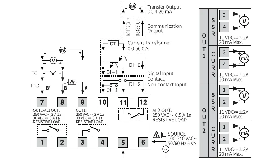
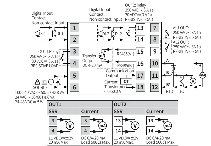
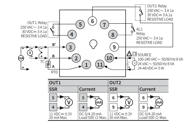
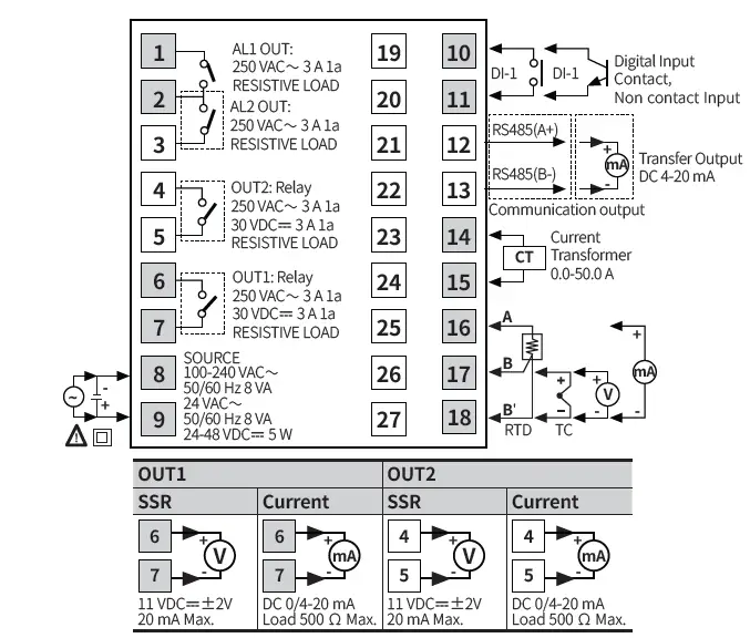
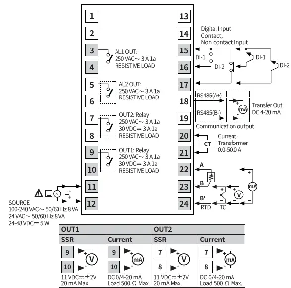
Connections
- Shaded terminals are standard model.
- Digital input is not electrically insulated from internal circuits, so it should be insulated when connecting other circuits.
TK4N
TK4S
TK4SP
TK4M
TK4H / W / L
Crimp Terminal Specification
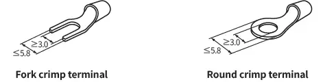
- Unit: mm, Use the crimp terminal of follow shape.
Initial Display When Power is ON
- When power is supplied, after all display will flash for 1 sec, model name is displayed sequentially. After input sensor type will flash twice, enter into RUN mode.
| 1. All display | 2. Model | 3. Input specification | 4. Run mode | |
| PV display part | ***8 | TK4 | TK4 | OPEN |
| SV display part | ***8 | 14RN | KCaH | 0 |
Mode Setting
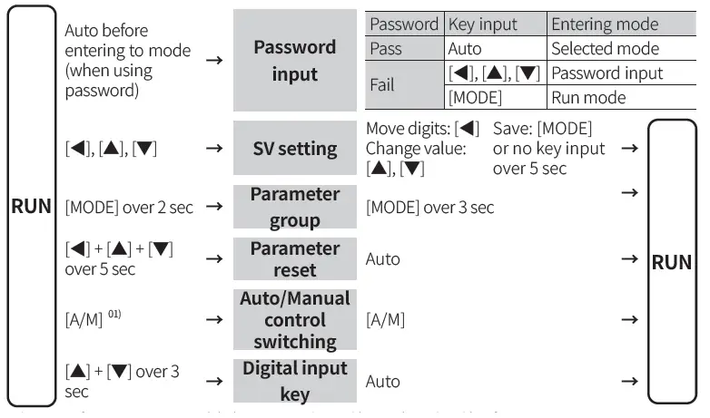
Parameter Setting
- Some parameters are activated/deactivated depending on the model or setting of other parameters.
- The ‘Parameter mask’ feature, which hide unnecessary or inactive parameters, and the ‘User parameter group’ feature, which quickly and easily set up certain parameters that are frequently used, can be set up in DAQMaster.
- Refer to the user manual for the details.
Parameter 1 group
| Parameter | Display | Default |
| Control output RUN/STOP | R-S | RUN |
| Multi SV selection | SV-N | SV-0 |
| Heater current monitoring | CT-A | )0 |
| Alarm output1 low limit | AL!L | 1550 |
| Alarm output1 high limit | AL!H | 1550 |
| Alarm output2 low limit | AL@L | 1550 |
| Alarm output2 high limit | AL@H | 1550 |
| Alarm output3 low limit | AL#L | 1550 |
| Alarm output3 high limit | AL#H | 1550 |
| Multi SV 0 | SV-0 | 0000 |
| Multi SV 1 | SV-1 | 0000 |
| Multi SV 2 | SV-2 | 0000 |
| Multi SV 3 | SV-3 | 0000 |
Parameter 2 group
| Parameter | Display | Default |
| Auto tuning RUN/STOP | AT | OFF |
| Heating proportional band | H-P | 01)0 |
| Cooling proportional band | C-P | 01)0 |
| Heating integral time | H-1 | 0000 |
| Cooling integral time | C-1 | 0000 |
| Heating derivative time | H-D | 0000 |
| Cooling derivative time | C-D | 0000 |
| Dead overlap band | DB | 0000 |
| Manual reset | REST | 05)0 |
| Heating hysteresis | hHYS | 002 |
| Heating OFF offset | hOST | 000 |
| Cooling hysteresis | cHYS | 002 |
| Cooling OFF offset | cOST | 000 |
| MV low limit | L-MV | `0)0 |
| MV high limit | H-MV | 10)0 |
| RAMP up change rate | RAMU | 000 |
| RAMP down change rate | RAMD | 000 |
| RAMP time unit | rUNT | MIN |
Parameter 3 group
| Parameter | Display | Default |
| Input specification | IN-T | KCaH |
| Temperature unit | UNIT | ?C |
| Analog low limit | L-RG | 0)00 |
| Analog high limit | H-RG | 1)00 |
| Scaling decimal point | DOT | )0 |
| Low limit scale | L-SC | 00)0 |
| High limit scale | H-SC | 10)0 |
| Display unit | dUNT | ?/O |
| Input correction | IN-B | 0000 |
| Input digital filter | MAvF | 00)1 |
| SV low limit | L-SV | -200 |
| SV high limit | H-SV | 1350 |
|
Control output mode |
O-FT | HEAT (Normal type) |
| H-C (Heating& Cooling type) | ||
|
Control type |
C-MD | PID (Normal type) |
| pP (Heating& Cooling- type) | ||
| Auto tuning mode | AtT | TUN1 |
| OUT1 control output selection | OUT1 | CURR |
| OUT1 SSR drive output type | O!SR | STND |
| OUT1 current output range | O!MA | 4-20 |
| OUT2 control output selection | OUT2 | CURR |
| OUT2 current output range | O@MA | 4-20 |
| Heating control cycle | H-T | 02)0 (Relay) 00@0 (SSR) |
| Cooling control cycle | C-T |
Parameter 4 group
| Parameter | Display | Default |
| Alarm output1 Operation mode | AL-1 | DVCC |
| Alarm output1 Option | AL!T | AL-A |
| Alarm output1 Hysteresis | A!HY | 001 |
| Alarm output1 contact type | A!N | NO |
| Alarm output1 ON delay time | A!ON | 0000 |
| Alarm output1 OFF delay time | A!OF | 0000 |
| Alarm output2 Operation mode | AL-2 | ]]DV |
| Alarm output2 Option | AL@T | AL-A |
| Alarm output2 Hysteresis | A@HY | 001 |
| Alarm output2 contact type | A@N | NO |
| Alarm output2 ON delay time | A@ON | 0000 |
| Alarm output2 OFF delay time | A@OF | 0000 |
| Alarm output3 Operation mode | AL-3 | OFF |
| Alarm output3 Option | AL#T | AL-A |
| Alarm output3 Hysteresis | A#HY | 001 |
| Alarm output3 contact type | A#N | NO |
| Alarm output3 ON delay time | A#ON | 0000 |
| Alarm output3 OFF delay time | A#OF | 0000 |
| LBA time | LBaT | 0000 |
| LBA band | LBaB | 002 (003) |
| Analog Transmission output1 Mode | AoM1 | PV |
| Transmission output1 low limit | FsL1 | -200 |
| Transmission output1 high limit | FsH1 | 1350 |
| Analog Transmission output2 Mode | AoM2 | PV |
| Transmission output2 low limit | FsL2 | -200 |
| Transmission output2 high limit | FsH2 | 1350 |
| Communication address | ADRS | 01 |
| Communication speed | BPS | 96 |
| Comm. parity bit | PRTY | NONE |
| Comm. stop bit | STP | 2 |
| Response time | RSWT | 20 |
| Comm. write | COMW | EnA |
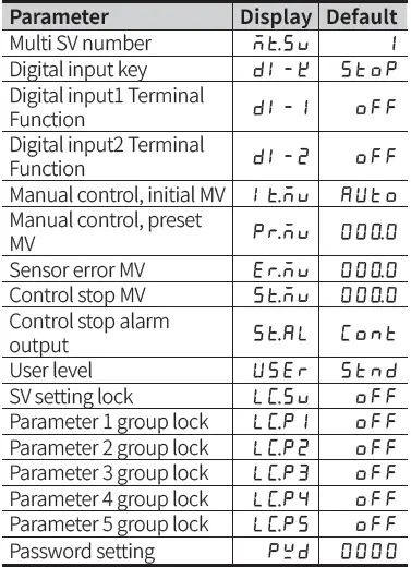
Parameter 5 group
CONTACTS
- 18, Bansong-ro 513Beon-gil, Haeundae-gu, Busan, Republic of Korea, 48002
- www.autonics.com
- +82-2-2048-1577
- [email protected]


