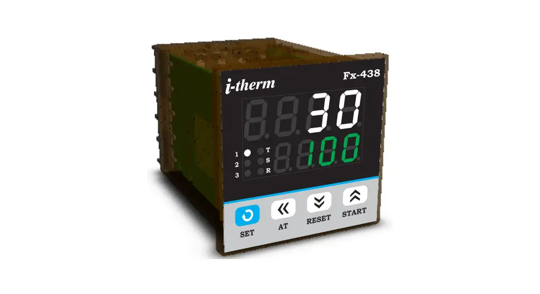
![]() Fx-438 PID Digital Temperature Controller
Fx-438 PID Digital Temperature Controller
User Manual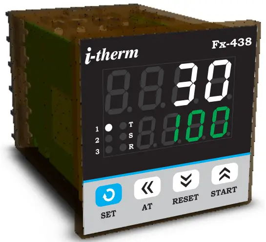 Fx – 438 (48 X 48)
USER’S OPERATING MANUAL FOR PID DIGITAL TEMPERATURE CONTROLLER
(Models: Fx – 438)
SPECIFICATIONS : –
1. DISPLAY TYPE : 8 – Digit 7 segment LED
| Model no. | Fx-438 | Display Colour |
| Display height (PV) | 0.36” | White |
| Display height (SV) | 0.24” | Green |
2. STATUS LED’S
1 : Control Output Status
2 : Output 2 Status
3 : Output 3 Status
R : Re-Transmission Status
S : Soak Time Status
T : Tune Status
3. INPUT
| Sensor Input | : TC-J,K,R,S,N,T,B & RTD (PT-100) |
| Analog Input | : 0 – 20mA, 4 – 20mA, 0 – 1VDC, 0 – 5VDC, 0 – 3.3VDC, 0 – 10VDC (Selectable) |
| Range | : -1999 to 9999 (Analog Input Only) |
| Resolution | : 0.001, 0.01, 0.1 & 1°C (Selectable for Analog Input only) |
| Sampling Time | : 125 msec. |
| Resolution | : 1°C |
| CJC for TC | : Built in automatic |
| LWC for Pt-100 | : Built in up to 18E max. |
| Digital Filter | : 1 to 10 Sec. |
4. RELAY OUTPUT
| Contact type | : N/O, COM |
| Contact Rating | : 5A @ 250VAC or 30 VDC |
| Life expectancy | : > 5,00,000 operations |
| Isolation | : Inherent |
5. SSR DRIVE OUTPUT
| Drive Capacity | : 12V @ 30mA. |
| Isolation | : Non-Isolated. |
6. FUNCTION
| Output 1 | : Main Control output (Factory Set) 1) Relay 2) SSR 3) mA (4~20 / 0~20) |
| Output 2 | : Programmable 1) Auxiliary control 2) Alarm 3) None |
| Output 3 | : 1)Auxiliary Control 2) Alarm 3) Soak Timer 4) None |
| Control Action | :ON-OFF/PID (Select) |
| Control Mode | : Heat/Cool (Select) |
7. ENVIRONMENTAL
| Operating Range | : 0 ~50°C, 5~90% Rh |
| Storage Humidity | : 95% Rh (Non-condensing) |
8. POWER SUPPLY
| Supply Voltage | : 90~270VAC, 50/60Hz. |
| Consumption | : 4W Maximum. |
9. PHYSICAL
Housing…………………: ABS Plastic
INSTALLATION GUIDELINES
- Prepare the cut-out with proper dimension as shown in figure.
- Remove clamp from Controller.
- Push the Timer through panel cut-out and secure the Controller in its place by tightening the side clamp.
SAFETY INSTRUCTION MECHANICAL
- Ambient temperature and relative humidity surrounding the Controller must not exceed the maximum specified limits.
- The Controller in its installed state must be protected against excessive electrostatic or electromagnetic interferences.
ELECTRICAL
- The Controller must be wired as per wiring diagram & it must comply with local electrical regulation.
- The Electrical noise generated by switching inductive loads might create momentary Fluctuation in display, latch up, data loss or permanent damage to the instrument. To reduce this use snubber circuit across the load.
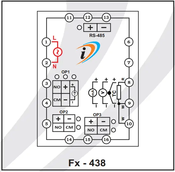
TERMINAL CONNECTIONS :
OVER ALL DIMENSIONS & PANEL CUT OUT (IN MM)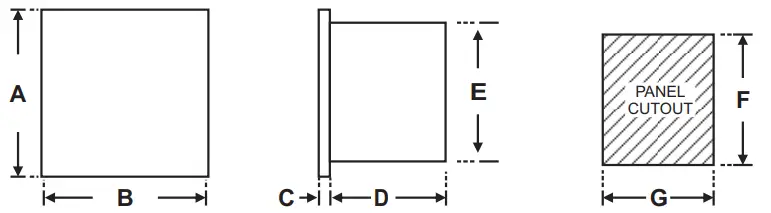
| Dim Model | A | B | C | D | E | F | G |
| Fx – 438 | 50 | 50 | 3 | 85 | 45 | 45 | 45 |
PROGRAMMING
RUN MODE : To access the run mode Press SHIFT key to change SP1
Para Meter | Lower Display | Upper Display | Range | Description | Default |
| Control Set Point |  |  | LSPL ~HSPL | User can change the SP1 value using UP/ DOWN and SHIFT keys. Holding the key will change the value at a faster rate. Press SET key to store the desired value. | 0oC |
USER LIST : To access the user list Press & Release SET key once.
| Para Meter | Lower Display | Upper Display | Range | Description | Default |
| Control Set Point | | | LSPL ~ HSPL | User can change the SP1 value using UP/ DOWN and SHIFT keys. Holding the key will change the value at a faster rate. Press SET key to store the desired value. | 0oC |
| Set Point 2 |  | | LSPL ~ HSPL -99 to 99 °C | This parameter will be prompted if Output 2 is configured as AUCn and SP2 is Enabled (1) Either absolute auxiliary control mode. (2) Either deviation auxiliary control mode. | 0oC |
| Set Point 3 |  | | LSPL ~ | This parameter will be prompted if Output 3 is configured as AUCn and SP3 is Enabled (1) Either absolute auxiliary control mode. (2) Either deviation auxiliary control mode. | 0oC |
| Ramp Rate |  |  | 0.0 oC to 25.0 oC | This parameter will be available only if Enabled in Configuration List. User can set ramp rate/min for SP1 (Set Point) to minimize overshoot. | Disable |
| Manual Power |  |  | 0 % to 100 % | This parameter will be prompted only if Manual power is Enabled from Control List. Manual Power means that the controller output power can be adjusted directly by the user. | 50 % |
| Op2 Mode |  | 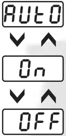 | ———- | This parameter is prompted only if Control Logic for Output1 is configured for Heat-Cool. OP 2 will be automatically activated /de-activated w.r.t SP1 & HYS. | Auto |
| OP 2 will be permanently Activated (ON). | |||||
| OP 2 will be permanently De-Activated (OFF). | |||||
| Alarm Set Point |  | | LSPL ~ HSPL-99 to +99°C 2 t o 9 9 ° C | This parameter is prompted if AL.SP is Enable & output 2 is configured as (1) Alarm (High/Low) mode. (2) As a deviation alarm mode. (3) As a band alarm. | 0oC |
| Alarm Set Point |  | | LSPL ~ HSPL -99 to +99°C 2 t o 9 9 °C | This parameter is prompted if AL.SP is Enable & output 2 is configured as (1) Alarm (High/Low) mode. (2) As a deviation alarm mode. (3) As a band alarm. | 0oC |
| Soak Time |  |  | 1 Sec to 9999 Hrs. | This parameter is prompted only if output 3 is configured as soak timer. Controller starts the execution of soak time as per the mode selected. Soak timer can be programmed using four different time base in Config. List. | 1 min. |
| Minute Elapsed |  |  | ——— | This parameter is prompted only if HOUR mode is selected in the Soak timer mode of OP3. (This is a View Only Parameter). During down counting of soak time it will display the remaining time & during up counting of soak time the elapsed time will be displayed. | ——- |
CONTROL LIST : To enter in this mode press SET & DOWN key simultaneously for 3 sec.
| Para Meter | Lower Display | Upper Display | Range | Description | Default |
| Lock Code |
| | 1 ~ 9999 | Set this parameter to 15 (Default LOCK CODE) to access Control List. User has a choice to set different Lock Code via USER LOCK CODE in Config. List. | 15 |
| Proportional Band |  | | 0.5to 99.9°C | This parameter will be prompted only if selected control action is PID. It sets bandwidth over which the output power is adjusted depending upon the error (SV-PV). The value of this parameter is automatically set by Auto tune function. | 5.0oC |

| Integral Time |  |
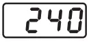
| 0 to 999 Sec. | This parameter will be prompted only if selected control action is PID. It sets the time taken by PID algorithm to remove steady state error. Value of this parameter is automatically set by Auto Tune function. If set to ‘0’, this function will be disabled. | 240 |
| Derivative Time |  |  | 0 to 300 Sec. | This parameter will be prompted only if selected control action is PID. It defines how strongly the Controller will react to the rate of change of PV. Value of this parameter is automatically set by Auto Tune function. If set to ‘0’, this function will be disabled. | 60 |
| Cycle Time |  |  | 0.5to 99.9 Sec. | This parameter will be prompted only if selected control action is PID. User can set this value based on process being controlled & type of Output being selected. For Relay O/P, cycle time should be more 12sec & for SSR O/P, cycle time should be less than 10sec. | 16.0 Sec. |
| Manual Power |  |
| This parameter will be prompted only if factory set control output is “mA”. If “Yes” Selected, Output power will be adjusted by user from User List. | No | |
| If “No” Selected, Output power will be Adjusted by instrument itself As per PID Routine. | |||||
| Output Power Limit |  |  | 0 % TO 100 % | This parameter will be prompted only if selected control action is PID. This parameter will decide the maximum output power in % applied to the load | 100 % |
| Soft Start Time |
| | 5 Sec. TO 300 Sec. | This parameter will be prompted only if factory set control output is “mA”. The soft start function suppresses the mA to become max. output. It places an upper limit on mA output for a specified amount of time1 after power on. This function is useful for effects such as suppressing the heater output during equipment startup & make load lightened. After the time has passed, the soft start function ends & normal PID control begin. | 50 Sec. |
| Output Off |  |  | 1 to 10 | This parameter will be prompted only if selected control action is PID. With this parameter control O/P will be Completely OFF after the Set Point + Offset Value. If Disable, O/P will act Depending upon the PID Value after Set Point achieved. | Disable |
| Tune Offset |  | | 50 % to 100 % | This parameter will be prompted only if selected control action is PID. This parameter allows the User to carry out Auto Tuning function below the set point. (If Tune offset is 50 % tuning will be carried out at 50 % of the set point and if 100 % tuning will be carried out at 100% of the set point.) | 100 % |
| Control Hys. 1 |  |  | 1 to 25 oC | This parameter will be prompted only if selected control action is ON-OFF. It sets the dead band between ON & OFF switching of the Output. Larger value of hysterisis minimize the number of ON-OFF operation of load.This increases life of actuators like contactors but also produces large errors (between PV & SV). | 2°C |
| Delay 1 |  | | 0 to 500 Sec. | This parameter will be prompted only if selected control action is ON-OFF. It sets the main output restart time where O/P once turned OFF will turn ON only after restart time, regardless difference between PV & SP in Heat or Cool mode. If set to ‘0’, O/P will be switched without delay. Also, Delay will be applicable in case of every power ON. | 0 Sec. |
| Hys. 2 |  | | 1 to 25 oC | This parameter will be prompted only it selected control mode for output2 is auxiliary control or an alarm. The value of this parameter sets the dead band between on and off switching of output load. | 2oC |
| Gap 1 |  |  | -9.9 to 9.9°C | This parameter will be prompted only if Control Logic for Output1 is configured for Heat-Cool. SP (set point) will be consider as (SP1 – Gap1) for heating. | 0 °C |
| Gap 2 |  | | -9.9to 9.9°C | This parameter will be prompted only if Control Logic for Output1 is configured for Heat-Cool. SP (set point) will be consider as (SP1 + Gap2) for cooling. | 0 °C |
| Delay 2 |  | | 0to 500Sec. | This parameter will be prompted only if output 2 is configured as an Auxiliary control output. In this mode, O/P once turned OFF will restart only after set time regardless of the difference between PV and SP2. Time delay is settable up to 500 seconds. If time delay is set to 0, there is no delay between output switching. | 0 Sec. |
| Hys. 3 |  | | 1 to 25 oC | This parameter will be prompted only it selected control mode for output2 is auxiliary control or an alarm. The value of this parameter sets the dead band between on and off switching of output load. | 2oC |

| Delay 2 | | | 0 to 500 Sec. | This parameter will be prompted only if output 2 is configured as an Auxiliary control output. In this mode, O/P once turned OFF will restart only after set time regardless of the difference between PV and SP2. Time delay is settable up to 500 seconds. If time delay is set to 0, there is no delay between output switching. | 0 Sec. |
| Soak Band |  | | 0.0 to 99°C. | This parameter defines the permissible deviation of PV from SP during soak time cycle. If PV falls outside the Soak band during soak cycle, Timer halts. Timer will start only when PV falls within the soak band. This parameter is ignored if set to ‘0’. | 0.0 |
| Soak Time Delay |  |  | 0 to 99 Sec. | This parameter will be prompted only if selected control mode for Output2 is Soak timer. Depending on end of soak strategy, the value of this parameter sets the activation time for OP2 when Soak timer is over. Setting this parameter to ‘0’ will make OP2 continuously ON at the end of Soak time till User starts the next cycle. | 10 Sec. |
CONFIGURATION LIST :
- To enter in this mode, Press and hold SET & UP key simultaneously for 3 sec.
- Press UP or DOWN key to scroll between parameter options.
- Press SET key to store the current parameter & move on to the next parameter.
| Para Meter | Lower Display | Upper Display | Description | Default |
| Lock Code |  | Set this parameter to 15 (Default LOCK CODE) to access Config. List. User has a choice to set different Lock Code between 1 to 9999 via USER LOCK CODE in Config. List. | 15 | |
| Input Types |  | 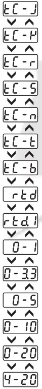 | ‘TC-J’ :- If selected, instrument will accept temperature input from thermocouple J type sensor at rear terminal. Below range it will display ‘LLLL’ message & above range it will display ‘HHHH’. | TC-J |
| ‘TC-K’ :- If selected, instrument will accept temperature input from thermocouple K type sensor at rear terminal. Below range it will display ‘LLLL’ message & above range it will display ‘HHHH’. | ||||
| ‘TC-R’ :- If selected, instrument will accept temperature input from thermocouple R type sensor at rear terminal. Below range it will display ‘LLLL’ message & above range it will display ‘HHHH’. | ||||
| ‘TC-S’ :- If selected, instrument will accept temperature input from thermocouple S type sensor at rear terminal. Below range it will display ‘LLLL’ message & above range it will display ‘HHHH’. | ||||
| ‘TC-N’ :- If selected, instrument will accept temperature input from thermocouple N type sensor at rear terminal. Below range it will display ‘LLLL’ message & above range it will display ‘HHHH’. | ||||
| ‘TC-T’ :- If selected, instrument will accept temperature input from thermocouple N type sensor at rear terminal. Below range it will display ‘LLLL’ message & above range it will display ‘HHHH’. | ||||
| ‘TC-B’ :- If selected, instrument will accept temperature input from thermocouple B type sensor at rear terminal. Below range it will display ‘LLLL’ message & above range it will display ‘HHHH’. | ||||
| ‘RTD’ :- If selected, instrument will accept temperature input from PT-100 sensor at rear terminal. Below range it will display ‘LLLL’ message & above range it will display ‘HHHH’. | ||||
| ‘RTD.1′ :- If selected, instrument will accept temperature input from PT-100 sensor at rear terminal. Below range it will display ‘LLLL’ message & above range it will display ‘HHHH’. | ||||
| ‘0 – 1′ :- If selected, instrument will accept 0 – 1VDC input at rear terminal. Below 0V it will display ‘LLLL’ message & above 1V it will display ‘HHHH’. | ||||
| ‘0 – 3.3′ :- If selected, instrument will accept 0 – 3.3VDC input at rear terminal. Below 0V it will display ‘LLLL’ message & above 3.3V it will display ‘HHHH’. | ||||
| ‘0 – 5′ :- If selected, instrument will accept 0 – 5 VDC input at rear terminal. Below 0V it will display ‘LLLL’ message & above 5V it will display ‘HHHH’. | ||||
| ‘0 – 10′ :- If selected, instrument will accept 0 – 10VDC input at rear terminal. Below 0V it will display ‘LLLL’ message & Above 10V it will display ‘HHHH’. | ||||
| ‘0 – 20′ :- If selected, instrument will accept 0 – 20 mA input at rear terminal. Below 0 mA it will display ‘LLLL’ message & Above 20 mA it will display ‘HHHH’. | ||||
| ‘4 – 20′ :- If selected, instrument will accept 4 – 20mA input at rear terminal. Below 3.8mA it will display ‘LLLL’ message & Above 20mA it will display ‘HHHH’. If input is less than 3.2mA it will display ‘L.BRK’(Loop Break) message. |
| Para Meter | Lower Display | Upper Display | Description | Default |
| mA Output Type |  | 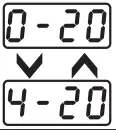 | This parameter will be prompted only if factory set control output is “mA”. If “0~20″ Selected, Control Output will be 0~20 mA. | 4~20 mA |
| If “4~20″ Selected, Control Output will be 4~20 mA. | ||||
| mA Function |  |  | User can select between PID or ON-OFF action algorithm to be adopted for output. If Factory set Control output is “mA” then Control mode as PID Selected & this parameter will be Skipped. | PID |
| User can select between PID or ON-OFF action algorithm to be adopted for output. If Factory set Control output is “mA” then Control mode as PID Selected & this parameter will be Skipped. | ||||
| RE-Tx Low Value |  | | By this parameter user can define Low scale for Retransmission. Which can be in between ‘-1999 to rE.Hi’. For range limit as per resolution selected Ref. Table No.2 (Page No. 9). | 0 |
| RE-TxHigh Value |  | By this parameter user can define High scale for Retransmission. Which can be in between ‘rE.Lo to 9999′. For range limit as per resolution selected Ref. Table No.2 (Page No. 9). | 1200 | |
| mA Low Calibration |  | 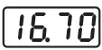 | This parameter will be prompted only if factory set control output is “mA”. By this parameter user can adjust Lower calibration for Selected mA type.(Adjust 0mA on meter if 0~20 selected or 4mA on meter if 4~20 selected). | 16.70 |
| mA High Calibration |  | 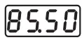 | This parameter will be prompted only if factory set control output is “mA”. By this parameter user can adjust Higher calibration for Selected mA type. (Adjust 20mA on Meter with this parameter). | 85.50 |
| mA Default |  | 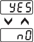 | This parameter will be prompted only if factory set control output is “mA” If “Yes” Selected, User Calibration will be replaced with Factory Calibration. | No |
| If “No” Selected, No change in User Calibration. | ||||
Resolution 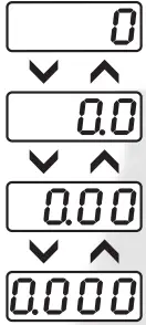 | This parameter will NOT be prompted when input type is selected as Thermocouple (TC-J,K,R & S). When input type selected is RTD then only “0 & 0.0″ resolution format will be available. By this parameter user can select four format of resolution only for analog input, i.e. “0.000, 0.00, 0.0, 0″. For range limit as per resolution selected Ref. Table No.6 (Page No. 10). | 0 | ||
| Analog Input Low Value |  | | By this parameter user can define Low scale for input signal. Which can be in between ‘-1999 to Ai.Hi’. For range limit as per resolution selected Ref. Table No.1(Page No. 5). | 0 |
Analog Input High Value  | By this parameter user can define HIGH scale for input signal. Which can be in between ‘Ai.Lo to 9999′. For range limit as per resolution selected Ref. Table No.1(Page No. 5). | 9999 | ||
| Lower SP Limit |  | | Sets the minimum limit for set point adjustment. It can be set from minimum specified range of selected sensor to HSPL value. | 0 oC |
| Higher SP Limit |  |  | Sets the maximum limit for set point adjustment. It can be set from LSPL value to maximum specified range of selected sensor. | 400 oC |
| Process Value Offset |  | | Function of this parameter is to add/subtract a constant value to the measured PV to obtain final PV for control applications. This parameter value can be altered : (i) To compensate for known thermal gradient. (ii) To match the display values with another recorder or indicator measuring the same PV. | 0 oC |
| Input Filter |  |  | The controller is equipped with an adaptive digital filter which is used to filter out any extraneous pulses on the PV. The filtered PV Value is used for all PV dependent functions. If the PV signal is fluctuating due to noise, increase the filter time constant value. | 4 |
| Control Mode |  | 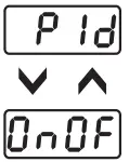 | User can select between PID or ON-OFF action algorithm to be adopted for output. If Factory set Control output is “mA” then Control mode as PID Selected & this parameter will be Skipped. | PID |
| Control Logic for OP 1 |  | 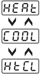 | User can select heating logic in which OP1 will remain ON till PV < SP. (PV increases when output is ON.) | Heat |
| User can select cooling logic in which OP1 will remain ON till PV > SP. (PV decreases when output is ON.) | ||||
| This parameter will be prompted only if selected input is RTD or RTD.1 and is used for BOD application. Here OP1 acts as Heating control & OP2 as Cooling control. | ||||
| Overshoot Control Point |  |  | This parameter will be prompted only if selected control action is PID. Setting this parameter on higher side will proportionally slows down the rate of rise of PV to minimize overshoot (this may cause delay to reach SP). Disabling or Setting this parameter on lower side will proportionally increase the rate of rise of PV ( which may cause overshoot). Disable this option if delay is not required to reach SP. (This may cause overshoot w.r.t. SP) | Disable |
| Ramp Rate |  |  | User can set the desired RAMP rate in USER list. | Disable |
| The RATE parameter will not be prompted in USER list. | ||||
| Auto Tune |  | | This parameter will be prompted only if selected control action is PID. If Enabled, this parameter will be prompted if user press Shift key for 3Sec. | Enable |
| If Disabled, this parameter will not be prompted if user press Shift key for 3Sec. | ||||
| Set Point 1 |  | | If Enabled, User can View & edit the Set point (SP1) in USER list. | Enable |
| If disabled, User can not View or edit Set Point (SP1) in USER list. | ||||
| Output 2 Mode |  | | This parameter will appear only if Control logic is Heat-Cool. If Enabled, User can set Diff. mode for OUTPUT 2 in USER list. | Disable |
| If disabled, User can not set Diff. mode for OUTPUT 2 in USER list. | ||||
| Output 2 Control |  |  | This parameter will appear only if Control logic is Heat-Cool. OP2 will be OFF at Ambient + OP2C value irrespective of output 2 mode. | 15.0 |
| Output 2 Function |  | 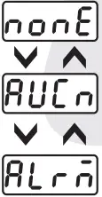 | This parameter allows the user to select output 2 as an ‘Auxiliary’ control. For options refer Table 2. | Auxiliary |
| This parameter allows the user to select output 2 as an ‘Alarm’ control. For options refer Table 3. | ||||
| This parameter the OP2 will be continuously OFF. | ||||
| Output 3 Function |  | 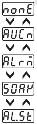 | This parameter allows the user to select output 3 as an ‘Auxiliary’ control. For options refer Table 2. | Auxiliary |
| This parameter allows the user to select output 3 as an ‘Alarm’ control. For options refer Table 3. | ||||
| This parameter allows the user to select output 3 as a ‘Soak’ mode. For options refer Table 4. | ||||
| This parameter allows the user to select output 3 to function as both ‘Alarm’ & ‘Soak’. For options refer Table 3 & 4. | ||||
| This parameter the OP3 will be continuously OFF. | ||||
| Device ID |  |  | Set device id for communication. Range:- 1 to 255. | 1 |
| Baud Rate |  |
| By this parameter user can select baud rate for communication purpose. | 9600 |
| Parity |  | 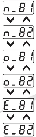 | By this parameter user can select parity for communication purpose. | O_81 |
| RS-485 response interval |  | | Widen the time interval of receving response ( Set value x 20 ms) | 1(20ms) |
| Lower Display Message |  |
| By pressing DOWN key, Lower display will Toggle between SP1-value, SP2- value, Alarm SP-Value(AL.SP) & Timer-value(SOAK). | Toggle |
| By this parameter Lower display will only show the SP1-value. | ||||
| By this parameter Lower display will only show the Timer value(SOAK TIME). | ||||
| User Lock Code |  |  | Default USER LOCK CODE is 15 to access Control & Configuration List. User has a choice to set its own USER LOCK CODE between 1 to 9999, this is to prevent unauthorized access of Control & Configuration List. | 15 |
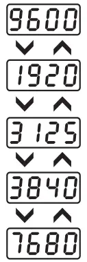
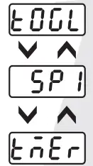
TABLE 2 : Below listed options will appear only if OP2 and / or OP3 is selected as an Auxiliary control mode.
| Parameter | Lower Display | Upper Display | Description | Default |
| OP2and/or OP 3 Mode | 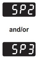 | 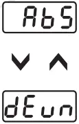 | This parameter will be prompted only if Output 2 is selected as an Auxiliary control output. In this mode, User can set SP2 value independently. The instrument works as 2-Set point Controller. | Abs |
| This parameter will be prompted only if Output 2 is selected as an Auxiliary control output. In this mode, User can set SP2 value which is always related to SP. User can set SP2 value with the deviation of ± 99°C w.r.t SP. | ||||
| OP 2 and/or OP 3Logic | 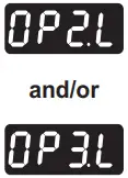 | 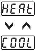 | User can select heating logic in which OP2 will remain ON till PV < SP2. (PV increases when output 2 is ON.) | Heat |
| User can select cooling logic in which OP2 will remain OFF till PV < SP2. (PV decreases when output 2 is ON.) | ||||
| Set Point 2 and/or Set Point 3 | 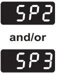 | 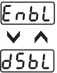 | If Enabled, User can View & edit the Set point (SP2) in USER list. | Enable |
TABLE 3 : Below listed parameters will appear only if OUTPUT 2 and / or OUTPUT 3 is selected as ALARM mode. In ALARM mode, Controller continuously compares PV with either SP (for Deviation or Band alarm) or an independent ALARM SP2 and /or SP3 (for process high and process low Alarm).
| Parameter | Lower Display | Upper Display | Description | Default |
| Alarm Type 1 and/o Alarm Type 2 | 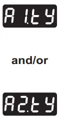 |  | Low Alarm : OP2 activates when PV<SP2.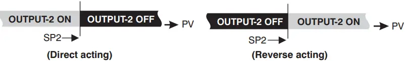 | High Dev. |
High Alarm : OP2 activates when PV>SP2.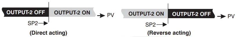 | ||||
Low Deviation Alarm : OP2 activates when PV is less than SP1 ± set deviation value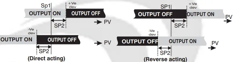 | ||||
High Deviation Alarm : OP2 activates when PV is greater than SP1 ± set deviation value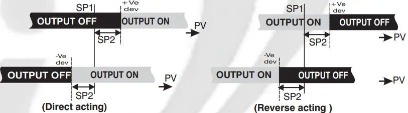 | ||||
Band Alarm : OP2 activates when PV falls outside the band w.r.t. SP1 in either direction.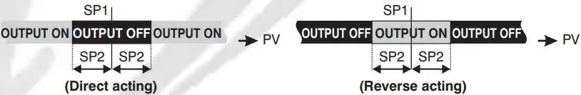 | ||||
| Alarm 1 and/or Alarm 2 Logic | 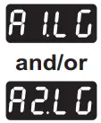 |  | If this parameter is set as ‘Direct’, Relay/SSR energizes under Alarm condition & remains De-energized otherwise. ‘Direct’ setting is generally used for Audio/Visual Alarm Output. |
Direct |
| If this parameter is set as ‘Reverse’, Relay/SSR De-energizes under Alarm condition & remains energized otherwise. ‘Reverse’ setting is generally used for tripping the process under Alarm condition. | ||||
| Alarm 1 and/or Alarm 2 Inhibit | 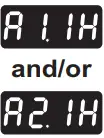 |
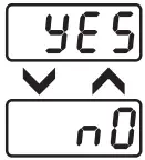
| This parameter can be used to inhibit (suppress) the Alarm activation upon power-up conditions by setting the parameter value to ‘YES”. From Power-up, the Alarm system remains disabled until PV is found with in the limits. |
No |
| If Alarm activation is desired even under Power-up condition, Set this parameter value to ‘NO’. | ||||
| Alarm 1 and/or Alarm 2 Ack. | 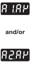 | 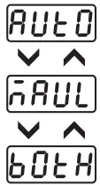 | Once Alarm is activated, user has following three options to de-activate it. When PV falls within the programmed limits, Alarm will be de-activated automatically. |
Auto |
| Once Alarm is activated, it remains activated until manually acknowledged by UP key. | ||||
| Once Alarm is activated, it can be de-activated either by pressing UP key or when PV falls within the alarm limits. | ||||
| Alarm 1 and/or Alarm 2 Set Point | 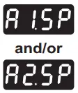 | 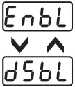 | If Enabled, User can View & edit the Alarm Set point in USER list. | Enable |
| If disabled, User can not View or edit Alarm Set Point in USER list. |
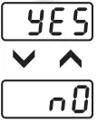
TABLE 4 : Below listed option will appear only if OP3 is selected as a soak timer.
| Parameter | Lower Display | Upper Display | Description | Default |
| END OF SOAK STRATEGY |  | 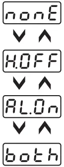 | It defines the behaviour of the controller at the end of soak timer cycle . Options are as below. If selected, the controller maintain PV at SP indefinitely irrespective of start or end of a soak timer. |
BOTH |
| The controller de-energizes OP1 as soon as the soak time is over. Here upper display will continue to show PV & lower display will show message “start”.Next cycle will start only when user press START key for 3 sec. | ||||
| The controller energizes OP2 for a time period programmed via (StdL) parameter at the end of a soak time cycle. User can utilise OP2 for audio/visual indication. | ||||
| The controller executes both, the Heater OFF and Alarm ON function as described above. | ||||
| TIME BASE SOAK TIMER |  | 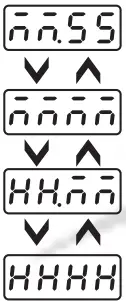 | User can select the timer base of soak time among the four options as shown. Minutes & Seconds (Range 99 minutes, 59 seconds). | MMMM |
| Minutes (Range 9999 minutes). | ||||
| Hours & Minutes (Range 99 Hours , 59 minutes). | ||||
| Hours (Range 9999 Hours). | ||||
| DIRECTION FOR SOAK TIME |  | If selected, soak timer will increment (from 0 to set value) (Note:- User can alter the new time value which should be > elapsed time even if soak timer is running. If user sets new time value < elapsed time, running timer will be terminated & End of soak Strategy will be executed. | DN | |
| If selected ,soak timer will decrement (from set value to 0). (Note:- User can alter the new time value even when soak timer is running. In this case, balance time of previous set value will be ignored & new cycle will be executed. | ||||
| RESET OF RUNNING SOAK TIME |  | 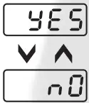 | If set as ‘YES’, soak time value will not be stored at the time of power failure. | NO |
| If set as ‘NO’ at power ON, soak time will continue from stored value. (Note: Seconds will not be stored.) | ||||
| TIMER START MODE |  | 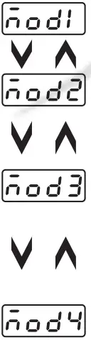 | User can define 4 different modes to start the soak timer as follows : – In this mode, Timer will start after pressing START key for 3 sec., irrespective of PV. |
MOD 2 |
| In this Mode, after power ON Timer starts when PV >= SV. To continue with next cycle, user has to either switch Power on & off OR press START key for 3 sec when STRT message is displayed on the lower display. | ||||
| In this Mode, Timer will start only after pressing START key for 3 sec & PV>=SV for any of the following conditions. (1) At every Power ON. (2) Completion of current soak time cycle. (3) Power failure during soak time is in progress. | ||||
| In this Mode, Timer will start only after pressing START key for 3 sec & PV>=SV for any of the following conditions. (1) At every Power ON. (2) Completion of current soak time cycle. After executing start command, if cycle doesn’t complete due to power failure, cycle will continue whenever PV >= SV after restore of power. No need to press START key. |
AUTO TUNING MODE : To enter in this mode, Press & hold SHIFT key for minimum 3 sec in the Run Mode.
| Parameter | Lower Display | Upper Display | Description | Default |
| Auto Tuning Mode |  | 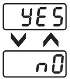 | This function will be executed only if selected control action is PID. Auto-tuning function is enabled by setting this parameter to ‘YES’. The AT led continuously flashes till Auto tuning function is in progress. During Auto-tuning, Controller learns the process characteristics by itself & calculates required P, I & D values. User can cancel or abort this feature by setting this parameter to ‘NO’. | No |
Table 5 :- Range of Different Sensor Types
| Sensor Type | Range | Resolution | Accuracy |
| Fe-k(J) T/C | 0 ~ 760oC | 1 oC | }± 1 oC |
| Cr-AL(K) T/C | -99 ~ 1300oC | 1 oC | |
| (R) T/C | 0 ~ 1700oC | 1 oC | |
| (S) T/C | 0 ~ 1700oC | 1 oC | |
| TC – N | -99 ~ 1300oC | 1 oC | |
| TC – T | -99 ~ 400oC | 1 oC | |
| TC – B | 0 ~ 1800oC | 1 oC | |
| Pt-100(RTD) | -100 ~ 450oC | 1 oC | |
| Pt-100(RTD 0.1) | –100.0 ~ 450.0oC | 0.1 oC | ± 0.3 oC |
Table 6 :– Range as per Resolution.
| Resolution | Analog Input Low Value | Analog Input High Value | Process Value Offset | Alarm 1 Band | Alarm 2 Band | ALARM 1 Hysterisis | ALARM 2 Hysterisis |
| 0000 | -1999to 9999 | -1999to 9999 | -25 to 25 | -50 to 50 | -50 to 50 | 1 to 25 | 1 to 25 |
| 000.0 | -199.9to 999.9 | -199.9to 999.9 | -25.0to 25.0 | -50.0to 50.0 | -50.0to 50.0 | 0.1to 25.0 | 0.1 to 25.0 |
| 00.00 | -19.99to 99.99 | -19.99to 99.99 | -15.00to 25.00 | -19.00to 50.00 | -19.00to 50.00 | 0.01to 25.00 | 0.01to 25.00 |
| 0.000 | -1.999to 9.999 | -1.999to 9.999 | -1.500to 2.500 | -1.900to 5.000 | -1.900to 5.000 | 0.001to 2.500 | 0.001to 2.500 |
Error Message:-
Display Message | Selected Input | Descriptions |
| “OPEN” | TC-J,K,R,S,N,B or RTD | Open Circuit of Control Sensor |
| “HHHH” | 0 ~ 20 / 4 ~ 20 / 0 ~ 10 | If input is above range it will display “HHHH” message. |
| “LLLL” | 0 ~ 20 / 0 ~ 10 | If input is below ‘0′ it will display “LLLL” message. |
| “LLLL” | 4 ~ 20 | If input is below “3.8mA” and above “3.2mA” it will display “LLLL” message. |
| “L.BRK” | 4 ~ 20 | If input is less than “3.2mA” it will display “L.BRK” (Loop Break) message. |
| “C.E.R.R.” | Any Input Selected | The device is out of calibration and need to be sent to factory for re-calibration. |
![]() Mfgd by: Innovative Instruments & Controls LLP
Mfgd by: Innovative Instruments & Controls LLP
338, New Sonal Link Service Industrial Premises Co-op Society Ltd,
Building No.2, Link Road, Malad (W), Mumbai – 400064.
Tel: 022-66939916/17/18;
E-mail : [email protected]
Website : www.itherm.co.in
OIM Fx-438 V2 Page 10 of 10 https://www.youtube.com/channel/UCzWGtv0HuHUgZR4KKRyKG1w/videos


