![]()
USER’S OPERATING MANUAL FOR PID DIGITAL TEMPERATURE CONTROLLER
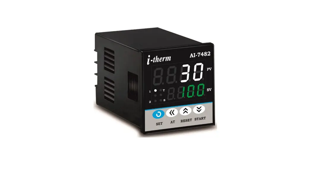
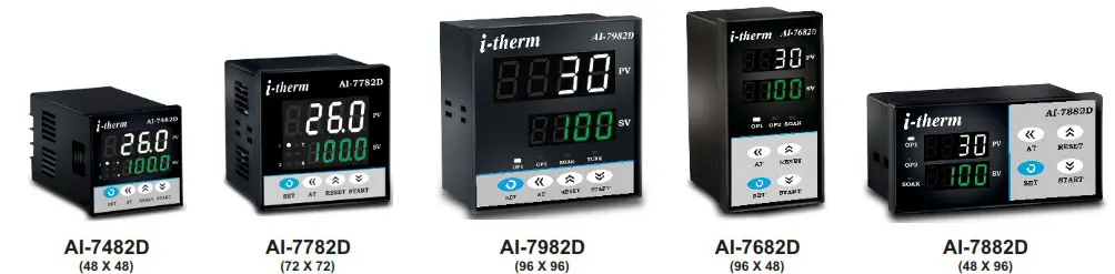
(Models : AI-7482D / AI-7782D / AI-7982D / AI-7682D / AI-7882D)
SPECIFICATIONS : –
| 1. DISPLAY TYPE | : Dual 4- Digit 7 Segment LED 4 Digit Bright White (PV) 4 Digit Luminous Green (SV) |
| Model No. | Al-7482D | AI-7782D | AI-7982D | AI-7682D | AI-7882D |
| Display height (PV) | 0.36″ | 0.56″ | 0.80″ | 0.36″ | 0.36″ |
| Display height (SV) | 0.24″ | 0.39″ | 0.56″ | 0.36″ | 0.36″ |
| STATUS LED’S | : OP 1 : Main Control Output OP 2 : Alarm Status SOAK : Soak Timer TUNE : Tuning Status (Only AI-7982 |
| 2. INPUT Sensor input Range | : TC:J,K,R,S,N,T,B & RTD: Pt-100 : Refer below table.} |
| Sensor Type | Range | Resolution | Accuracy |
| Fe-k(J) T/C | 0 ~ 760°C | 1 °C | |
| Cr-AL(K) T/C | -99 ~ 1300°C | 1 °C | |
| (R)T/C | 0 ~ 1700°C | 1 °C | |
| (S)T/C | 0 ~ 1700°C | 1 °C | |
| TC – N | -99 ~ 1300°C | 1 °C | |
| TC – T | -99 ~ 400°C | 1 °C | |
| TC – B | 0 ~ 1800°C | 1 °C | |
| Pt-100(RTD) | -100 ~ 450°C | 1 °C | |
| Pt-100(RTD 0.1) | -99.9 ~ 450.0°C | 0.1 °C | ± 0.3 °C |
| Sampling Time Resolution CJC for TC LWC for Pt-100 Digital Filter | : 125 msec. : 1°C/0.1°C(Only for RTD) : Built in automatic : Built in upto 18E max. : 1 to 10 Sec. |
| 3. RELAY OUTPUT Contact type Contact Rating Life expectancy Isolation | : N/O, CM, N/C : 5A @ 250VAC or 30 VDC : > 5,00,000 operations : Inherent |
| 4. SSR DRIVE OUTPUT Drive Capacity Isolation | : 12V @ 30mA. : Non-Isolated. |
| 5. FUNCTION Output 1 Output 2 | : Main Control output : Programmable 1) Auxiliary control 2) Alarm 3) Soak timer 4) Alarm + Soak timer |
| Control Action Control Mode Compliance | : ON-OFF/PID (Select) : Heat/Cool (Select) : —- |
| 6. ENVIRONMENTAL Operating Range Storage Humidity | : 0 ~50°C, 5~90% Rh : 95% Rh (Non-condensing) |
| 7. POWER SUPPLY Supply Voltage Consumption | : 90~270VAC, 50/60Hz. : 4W Maximum. |
| 8. PHYSICAL Housing | : ABS Plastic |
SAFETY INSTRUCTION :
This controller is meant for temperature control applications. It is important to read the manual prior to installing or commissioning of controller. All safety related instruction appearing in this manual must be followed to ensure safety of the operating personnel as well as the instrument.
GENERAL
- The controller must be configured correctly for intended operation. Incorrect configuration could result in damage to the equipment or the process under control or it may lead personnel injury.
- The controller is generally part of control panel and in such a case the terminals should not remain accessible to the user after installation.
MECHANICAL
- The Controller in its installed state must not come in close proximity to any corrosive/combustible gases, caustic vapours, oils, steam or any other process by- products.
- The Controller in its installed state should not be exposed to carbon dust, salt air, direct sunlight or radiant heat.
- Ambient temperature and relative humidity surrounding the controller must not exceed the maximum specified limit for proper operation of the controller.
- The controller in its installed state must be protected against excessive electrostatic or electromagnetic interferences. Ventilation holes provided on the chassis of the instrument are meant for thermal dissipation hence should not be obstructed in the panel.
ELECTRICAL
- The controller must be wired as per wiring diagram & it must comply with local electrical regulation.
- Care must be taken not to connect AC supplies to low voltage sensor input.
- Circuit breaker or mains s/w with fuse (275V/1A) must be installed between power supply and supply terminals to protect the controller from any possible damage due to high voltage surges of extended duration.
- Circuit breaker and appropriate fuses must be used for driving high voltage loads to protect the controller from any possible damage due to short circuit on loads.
- To minimize pickup of electrical noise, the wiring for low voltage DC and sensor input must be routed away from high current power cables. Where it is impractical to do this, use shielded ground at both ends.
- The controller should not be wired to a 3-Phase supply with unearthed star connection. Under fault condition such supply could rise above 264 VAC which will damage the controller.
- The Electrical noise generated by switching inductive loads might create momentary Fluctuation in display, alarm latch up, data loss or permanent damage to the instrument. To reduce this use snubber circuit across the load.
- It is essential to install a over Temp. Protection device to avoid any failure of heating system. Apart from spoiling the product, this could damage the process being controlled.
CAUTION: To prevent the risk of electrical shock, switch off the power before making/removing any connection or removing the controller from its enclosure.
MECHANICAL INSTALLATION
The label on the controller identifies the serial number, wiring connections and batch number.
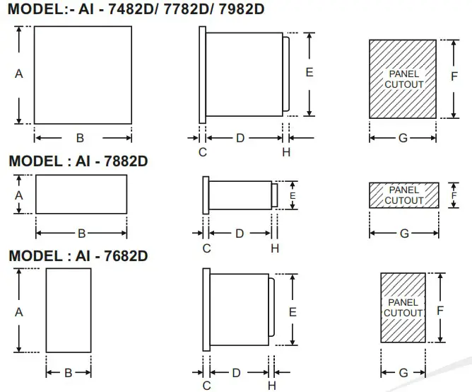
OVER ALL DIMENSIONS & PANEL CUT OUT (IN MM)
MODEL:- AI – 7482D/ 7782D/ 7982D
![]()
INSTALLATION GUIDELINES :
- Prepare the cut-out with proper dimension as shown in figure.
- Remove clamp from controller
- Push the controller through panel cut-out and secure the controller in its place by tightening the side clamp.
ELECTRICAL INSTALLATION
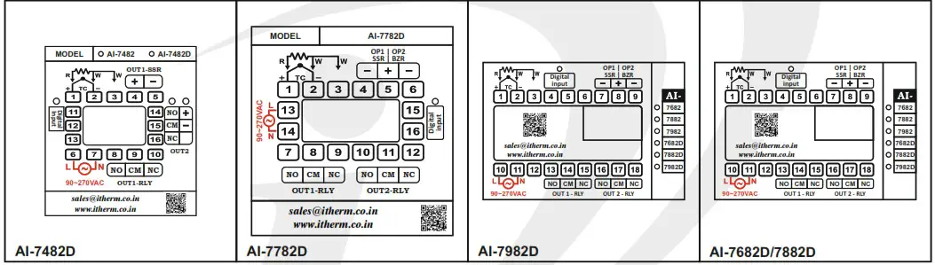
The electrical connection diagram is shown on the controller enclosure as below.
FRONT PANEL LAYOUT
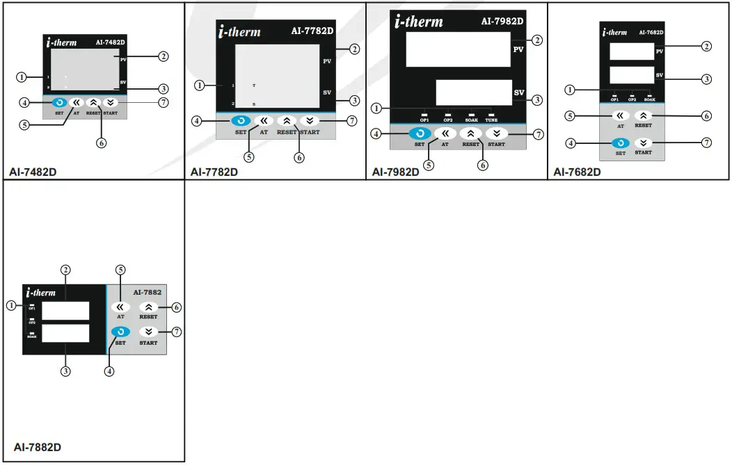
FRONT PANEL LAYOUT DESCRIPTION :
| Sr. | NAME | FUNCTION |
| 1 | OP1 LED | Glows when OP1 is ON & flashes when delay time (dlyl) is in operation (if selected mode is ON-OFF) |
| OP2 LED | Glows when OP2 is ON & flashes when alarm condition persists even after acknowledged OR delay time (dly2) is in operation & selected mode is ON-OFF | |
| SOAK LED | Glows when Soak mode is selected & flashes when soak timer is in operation. | |
| 2 | UPPER DISPLAY | It will display (1) Measured value of selected input or Error messages in run mode. (2) Parameters value in program mode. |
| 3 | LOWER DISPLAY | It will display (1) SP (Main set point) / SP2 (Auxiliary/Alarm) set value / Set Soak time value/ balance or elapsed soak time in run mode. (2) Parameter code in program mode. |
| 4 | SET KEY | (1) For SP programming. (2) To access Control mode. (3) To access Configuration mode along with UP key. (4) To scroll the parameter & to store its value. |
| 5 | SHIFT KEY | (1)To increase/alter parameter value in program mode with Up / Dn key. (2)Press for 3sec in programming, this will help to go back to previous parameter. |
| 6 | UP KEY | (1) To increase/alter parameter value in program mode. (2) To enter in configuration mode (with SET key). (3) To acknowledge Alarm. (4) To enter in tune mode (with DOWN key). |
| 7 | DOWN KEY | (1) To decrease/alter parameter value in program mode. (2) To enter in tune mode (with UP key). |
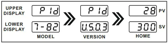
POWER UP: At power on, following sequence will be prompted on the display till it reaches to Home display mode.
In home display mode, by pressing DOWN key, User can view the set value of SP1 & SP2 (if OP2 = AUXILIARY or ALARM mode) or timer value(if OP2 = soak mode) sequentially.
Here, Lower display will show SP1-value, SP2-value, Alarm SP-Value & Timer-value by pressing DOWN key and it’s respective parameter code (SP1/SP2/AL.SP/SOAK TIME) by pressing UP key.
PROGRAMMING
USER LIST : To access the user list press SET key once.
| PARA METER | LOWER DISPLAY | UPPER DISPLAY | RANGE | DESCRIPTION | DEFAULT | |
| CONTROL SET POINT | LSPL – Haply | User can change SP1 value using UP/ DOWN keys. Holding the key, will change the value at a faster rate. Press SET key to store the desired value & move on to the next parameter. | 0°C | |||
| RAMP RATE | 0.0 °C to 25.0 °C | This parameter will be available only if Enabled in Configuration List. User can set ramp rate/min for SP1 (Set Point) to minimize overshoot. | Disable | |||
| OP2 MODE | —— | This parameter is prompted only if Control Logic for Output 1 is configured for Heat-Cool. Output 2 will be automatically activated /de-activated w.r.t SP1 & HYS. | Auto | |||
| Output 2 will be permanently Activated (ON). | ||||||
| Output 2 will be permanently De-Activated (OFF). | ||||||
| SET | LSPL – HSPL 2 to9°C | -99 to 9+99°C This parameter is prompted if SP2 is Enable & output 2 is configured as (1)Either absolute auxiliary control or as an alarm (High/Low) mode. (2)Either deviation auxiliary control or as a deviation alarm mode. (3)As a band alarm(For all above SP2 has to be enable). | 0°C | |||
| SOAK TIME | 1 Sec to 9999 Hrs. | This parameter is prompted only if output 2 is configured as soak timer. Controller starts the execution of soak time as per the mode selected. Soak timer can be programmed using four different time base in Config. List. | 1 min. | |||
CONTROL LIST : To enter in this mode, press SET & DOWN key simultaneously for 3 sec. User can then set the following control parameters.
| PARA METER | LOWER DISPLAY | UPPER DISPLAY | RANGE | DESCRIPTION | DEFAULT |
| LOCK CODE | 1 – 9999 | Set this parameter to 15 (Default LOCK CODE) to access Control List. User has a choice to set different Lock Code via USER LOCK CODE in Config. List. | 0 | ||
| PROPOR TIONAL BAND | 0.5 99.9°C | to This parameter will be prompted only if selected control action is PID. It sets proportional band over which the output power is adjusted depending upon the error (SV-PV). Value of this parameter is automatically set by Auto tune function. | 5.0°C | ||
| INTEGRAL TIME | to0 9999 Sec. | This parameter will be prompted only if selected control action is PID. It sets the time taken by algorithm to remove steady state error. Value t th ti tk b PIDl ith t td tt Vl of this parameter is automatically set by auto tune function. If set to ‘0’, this function will be disabled. | 240 | ||
| DERIV DYNETIME | 0 to 300 Sec. | This parameter will be prompted only if selected control action is PID. It defines how strongly the controller will react to rate of change of PV. Value of this parameter is automatically set by auto tune function. If set to ‘0’, this function will be disabled. | 60 | ||
| CYCLE TIME | 0.5 to 100.0 Sec. | This parameter will be prompted only if selected control action is PID. User can set this value based on process being controlled & type of output being selected. For Relay 0/P, cycle time should be more than 12sec & for SSR 0/P, cycle time should be less than 10sec. | sa.a lb U sec. | ||
| OUTPUT POWER LIMIT | 0.0 % to 100.0 % | This parameter will be prompted only if selected control action is PID. This parameter will decide the maximum output power in % applied to the load. | 100 °A) | ||
| OUTPUT OFF | 1 to10 | This parameter will be prompted only if selected control action is PID. With this parameter 0/P will be Completely OFF after the Set Point + Offset Value. If Disable, 0/P will act Depending upon the PID Value after Set Point achieved. | Disable | ||
| TUNE OFFSET | 50 % to 100 % | This parameter will be prompted only if selected control action is PID. This parameter allows the User to carry out Auto Tuning function below the set point. (If tune offset is set to 50 %, tuning will be carried out at 50 % of the set point and if set to 100 %, tuning will be carried out at 100 % of the set point.) | 100% | ||
| CONTROL HYS | o 1 to 25 C | This parameter will be prompted only if selected control action is ON – OFF. It sets the dead band between ON & OFF switching of the Output. Larger value of hysteresis minimize the number of ON-OFF operation to the load. This increases life of actuators like contactors but, also produces large errors (between PV & SV). | 2°C | ||
| DELAY 1 | 0 to 500 Sec. | This parameter will be prompted only if selected control action is ON – OFF. It sets the main output Delay time where O/P once turned OFF will turn ON only after Delay time, regardless difference between PV & SP. Also, Delay will be considered at every power ON. | 120 Sec. | ||
| HYS 2 | o 1 to 25 C | This parameter will be prompted only if selected control mode for output2 is Auxiliary control or an Alarm. The value of this parameter sets the dead band between ON & OFF switching of output load. | 2°C | ||
| GAP 1 | -9.9 to 9.9°C | This parameter will be prompted only if Control Logic for Output1 is configured for Heat-Cool. SP (set point) will be consider as (SP-Gap1) for heating. | 0°C | ||
| GAP 2 | -9.9 to 9.9°C | This parameter will be prompted only if Control Logic for Output1 is configured for Heat-Cool. SP (set point) will be consider as (SP+Gap2) for cooling. | 0°C | ||
| DELAY 2 | 0 to 500 Sec. | This parameter will be prompted only if Output2 is configured as an Auxiliary control output OR Control Logic is configured for Heat-Cool. In this mode, it sets the output Delay time where O/P once turned OFF will turn ON only after Delay time, regardless difference between PV & SP2. Also, Delay will be considered at every power ON. | 0 Sec. | ||
| SOAK TIME DELAY | 0 to 99 Sec. | This parameter will be prompted only if selected control mode for Output2 is Soak timer. Depending on end of soak strategy, the value of this parameter sets the activation time for OP2 when Soak timer is over. Setting this parameter to ‘0’ will make OP2 continuously ON at the end of Soak time till User starts the next cycle. | 10 Sec. | ||
| SOAK BAND | 0.0 to 99 ºC. | This parameter defines the permissible deviation of PV from SP during soak time cycle. If PV falls outside the Soak band during soak cycle, Timer halts. Timer will start only when PV falls within the soak band. This parameter is ignored if set to ‘0’. | 0 Sec. |
CONFIGURATION LIST :
- To enter in this mode, press and hold SET & UP key simultaneously for 3 sec.
- Press UP or DOWN key to scroll between parameter options.
- Press SET key to store current parameter & move on to the next parameter.
| PARA METER | LOWER DISPLAY | UPPER DISPLAY | DESCRIPTION | DEFAULT | |||||||||||||||||||||||
| LOCK CODE | Set this parameter to 15 (Default LOCK CODE) to access Config. List. User have a choice to set different Lock Code via USER LOCK CODE in Config. List. | 0 | |||||||||||||||||||||||||
| INPUT TYPE | This parameter value is set according to the type of sensor (Thermocouple or RTD input) connected to the controller’s input terminals.
| TC – J |
| PARA METER | LOWER DISPLAY | UPPER DISPLAY | DESCRIPTION | DEFAULT | ||||||||||||||||
| INPUT TYPE | This parameter value is set according to the type of sensor (Thermocouple or RTD input) connected to the controller’s input terminals.
| T0 – J | ||||||||||||||||||
| LOWER SET POINT LIMIT | Sets the minimum limit for set point adjustment. It can be set from minimum specified range of selected sensor to HSPL value. | 0°C | ||||||||||||||||||
| HIGHER SET POINT LIMIT | Sets the maximum limit for set point adjustment. It can be set from LSPL value to maximum specified range of selected sensor. | 400°C | ||||||||||||||||||
| PROCESS OFFSET | VALUE Function of this parameter is to add/subtract a constant value to the measured PV to obtain Final PV for control applications. This parameter value needs to be altered for one of the following reason : – (i) To compensate for known thermal gradient. (ii)To match the display values with another recorder or indicator measuring the same PV. | 0°C | ||||||||||||||||||
| INPUT FILTER | The controller is equipped with an adaptive digital filter which is used to filter out any extraneous pulses on the PV. The filtered PV Value is used for all PV dependent functions. If the PV signal is fluctuating due to noise, increase the filter time constant value. | 6 | ||||||||||||||||||
| CONTROL MODE FOR 0/P 1 | User can select between PID or ON-OFF action algorithm to be adopted for | PID | ||||||||||||||||||
| CONTROL LOGIC FOR 0/P 1 | User can select heating logic in which OP1 will remain ON till PV < SP. (PV increases when output is ON.) | Heat | ||||||||||||||||||
| User can select cooling logic in which OP1 will remain ON till PV > SP. (PV decreases when output is ON.) | ||||||||||||||||||||
| This parameter will be prompted only if selected input is RTD or RTD.1 and is used for BOD application. Here OP1 acts as Heating control & OP2 as Cooling control. | ||||||||||||||||||||
| OVER SHOOT CONTROL POINT | This parameter will be prompted only if selected control action is PID. Setting this parameter on higher side will proportionally slows down the rate of rise of PV to minimize overshoot (this may cause delay to reach SP). Setting on lower side will proportionally or disabling this parameter will increase the rate of rise of PV (which may cause overshoot). Disable this option if delay is not required to reach SF’. | Disable | ||||||||||||||||||
| RAMP RATE | This parameter will be prompted only if OCP (over shoot control point) is disabled. When enabled, User can set the desired RAMP rate in USER list. | Disable | ||||||||||||||||||
| When disabled, this parameter will not be prompted in USER list. | ||||||||||||||||||||
| AUTO TUNE | This parameter will be prompted only if selected control action is PID. If Enabled, this parameter will be prompted if user press Up & Down keys Simultaneously for 3Sec. | Enable | ||||||||||||||||||
| If Disabled, this parameter will not be prompted if user press Up & Down keys Simultaneously for 3Sec. |
| PARA METER | LOWER DISPLAY | UPPER DISPLAY | DESCRIPTION | DEFAULT |
| SET POINT 1 | If Enabled, User can View & edit the Set point (SP1) in USER list. | Enable | ||
| If disabled, User can only View the Set Point (SP1) but Can not edit it in USER list. | ||||
| OUTPUT 2 MODE | This parameter will appear only if Control logic is Heat-Cool. If Enabled, User can set Diff. mode for OUTPUT 2 in USER list. | Disable | ||
| If disabled, User can not set Diff. mode for OUTPUT 2 in USER list. | ||||
| OUTPUT 2 CONTROL | This parameter will appear only if Control logic is Heat-Cool. OP2 will be OFF at Ambient + OP2C value irrespective of output 2 mode. | 15.0 | ||
| OUTPUT 2 FUNCTION | When NONE is selected, Output 2 will be permanently de-activated. | Auxiliary | ||
| This parameter allows the user to select output 2 as an ‘Auxiliary’ control. For options refer Table 3. | ||||
| This parameter allows the user to select output 2 as an ‘Alarm’ control. For options refer Table 4. | ||||
| This parameter allows the user to select output 2 as a ‘Soak’ mode. For options refer Table 5. | ||||
| This parameter allows the user to select output 2 to function as both ‘Alarm’ & ‘Soak’. For options refer Table 4 & 5. | ||||
| DIGITAL INPUT FUNCTION | This parameter helps in selecting the functionality of Digital Input. When NONE is selected, Digital Input will be permanently de-activated. | LWL | ||
| By selecting this parameter, Digital Input can be used as Water Level Indicator input. | ||||
| By selecting this parameter, Digital Input can be used to start soak timer. | ||||
| By selecting this parameter Digital Input can be used to detect whether the door is open or closed. | ||||
| DIGITAL INPUT TIMING | Digital Input will be detected after selected timing. The range of Digital Input timing will be from 0 to 99 sec. | 3 sec. | ||
| ALARM INPUT TIMING | Alarm output will be generated after the completion of alarm time and detection of Digital Input. The range of Alarm Input timing will be from 0 to 99 sec. | 0 sec. | ||
| LOWER DISPLAY MESSAGE | By pressing DOWN key, Lower display will Toggle between SP1-value, SP2- value, Alarm SP-Value(AL.SP) & Timer-value(SOAK). | SP1 | ||
| By this parameter Lower display will only show the SP1-value. | ||||
| By this parameter Lower display will only show the Timer value(SOAK TIME). | ||||
| By this parameter Lower display will show Setpoint till soak timer has not started and afterwards, it will display the Timer value(SOAK TIME). This parameter will appear only if Output 2 is set as SOAK/ AL.ST | ||||
| LOWER DISPLAY RAMPING SETPOINT | If Enabled, User can View ramping setpoint. This parameter will appear only if Ramp rate is enabled. | Enable | ||
| If disabled, User can View target setpoint. This parameter will appear only if Ramp rate is enabled. |
| USER LOCK CODE | Default USER LOCK CODE is 15 to access Control & Configuration List. User has a choice to set its own USER LOCK CODE between 1 to 9999, this is to prevent unauthorized access of Control & Configuration List. | 15 |
TABLE 3 : Below listed options will appear only if OP2 is selected as an Auxiliary Control Mode .
| PARA METER | LOWER DISPLAY | UPPER DISPLAY | DESCRIPTION | DEFAULT |
| SET POINT 2 | If selected, User can set SP2 value independently, irrespective of SP1. | ABS | ||
| In this mode SP2 is always related with SP1. User can set SP2 value with deviation of ± 99°C w.r.t SP1. | ||||
| OUTPUT 2 LOGIC | User can select Heat logic for control Output 2 in which OP2 will remain ON till PV<SP2 (PV increases when output is ON). | |||
| Heat User can select Cool logic for control Output 2 in which OP2 will remain ON till PV> SP2 (PV decreases when output is ON). | ||||
| SET POINT 2 | If Enabled, User can View & edit the Set point (SP2) in USER list. | Enable | ||
| If disabled, User can not View or edit Set Point (SP2) in USER list. |
TABLE 4 : Below listed points will appear only if O/P2 is selected as an Alarm mode. In Alarm mode, Controller continuously compares PV with either SP (for deviation or Band -alarm) or an independent Alarm set points (for process high and process low alarm). HYS2 in Control list decides when to switch OFF the Alarm.
| PARA METER | LOWER DISPLAY | UPPER DISPLAY | DESCRIPTION | DEFAULT |
| ALARM TYPE | Direct acting Reverse acting | Low | ||
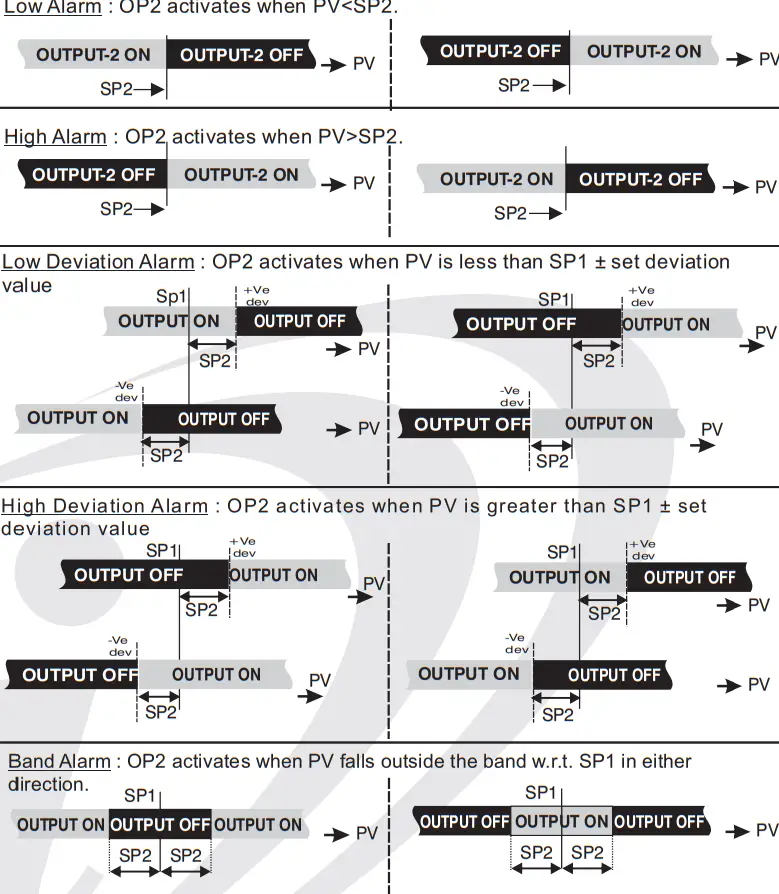 | ||||
| ALARM LOGIC | User can select direct Alarm Logic in which OP2 will be ON under alarm condition; otherwise OFF (used for audio visual alarm). | Direct | ||
| User can select Reverse Alarm Logic in which OP2 will be ON in normal conditions & will be OFF under alarm conditions (used to trip the process in alarm conditions). | ||||
| ALARM INHIBIT | If this parameter is set as ‘YES’ & Alarm condition persists, it will Disable Alarm 0/P at power ON. | No | ||
| If this parameter is set as ‘NO’ & Alarm condition persists, it will Enable Alarm 0/P at power up. | ||||
| ALARM ACK. | Once the Alarm is activated, User has following three options to de-activate it. When PV falls within the programmed limits The Alarm will be de-activated automatically. | Auto | ||
| Once the alarm is activated, it remains activated until acknowledged manually by UP key. | ||||
| Once the alarm is activated, it can be de-activated either by pressing UP key or when PV falls within the alarm limits. | ||||
| ALARM SET POINT | If Enabled, User can View & edit the Alarm Set point in USER list. | Enable | ||
| If disabled, User can not View or edit Alarm Set Point in USER list. |
TABLE 5 : Below listed option will appear only if OP2 is selected as a soak timer.
| PARA METER | LOWER DISPLAY | UPPER DISPLAY | DESCRIPTION | DEFAULT | ||
| END OF SOAK STRATEGY | It defines the behaviour of the controller at the end of soak timer cycle . Options are as below. If selected, the controller maintain PV at SP indefinitely irrespective of start or end of a soak timer. | BOTH | ||||
| The controller de-energizes OP1 as soon as the soak time is over. Here upper display will continue to show PV & lower display will show message “start”. NeXT cycle will start only when user press START key for 3 sec. | ||||||
| The controller energizes OP2 for a time period programmed via (Still) parameter at the end of a soak time cycle. User can utilize OP2 for audio/visual indication. | ||||||
| The controller executes both, the Heater OFF and Alarm ON function as described above. | ||||||
| TIME BASE SOAK TIMER | User can select the timer base of soak time among the four options as shown. Minutes & Seconds (Range 99 minutes, 59 seconds). | MMMM | ||||
| Minutes (Range 9999 minutes). | ||||||
| Hours & Minutes (Range 99 Hours , 59 minutes). | ||||||
| Hours (Range 9999 Hours). | ||||||
| DIRECTION FOR TAME | If selected, soak timer will increment (from 0 to set value) (Note:- User can alter the new time value which should be > elapsed time even if soak timer is running. If user sets new time value < elapsed time, running timer will be terminated & End of soak Strategy will be executed. | DN | ||||
| If selected ,soak timer will decrement (from set value to 0). (Note:- User can alter the new time value even when soak timer is running. In this case, balance time of previous set value will be ignored & new cycle will be executed. | ||||||
| RESET OF RUNNING SOAK TIME | If set as ‘YES’, soak time value will not be stored at the time of power failure. | NO | ||||
| If set as ‘NO’ at power ON, soak time will continue from stored value. (Note: Seconds will not be stored.) | ||||||
| TIMER START MODE | User can define 4 different modes to start the soak timer as follows : – In this mode, Timer will start after pressing START key for 3 sec., irrespective of PV. | MOD 2 | ||||
| In this Mode, after power ON Timer starts when PV >= SV. To continue with next cycle, user has to either switch Power on & off OR press START key for 3 sec when STRT message is displayed on the lower display. | ||||||
| In this Mode, Timer will start only after pressing START key for 3 sec & PV>=SV for any of the following conditions. (1)At every Power ON. (2)Completion of current soak time cycle. (3)Power failure during soak time is in progress. | ||||||
| In this Mode, Timer will start only after pressing START key for 3 sec & PV>=SV for any of the following conditions. (1)At every Power ON. (2)Completion of current soak time cycle. After executing start command, if cycle doesn’t complete due to power failure, cycle will continue whenever PV >= SV after restore of power. No need to press START key. | ||||||
| AUTO TUNING MODE | This function will be executed only if selected control action is PID & Auto tune is Enable. The Auto-tuning function can be initiated by setting this parameter to YES. The decimal of LSB flashes till auto tuning function is in progress. During Auto-tuning, The controller learns the process characteristics by itself & calculates required P, I & D values. User can cancel or abort this feature by setting this parameter to NO. | NO | ||||
USER GUIDE : –
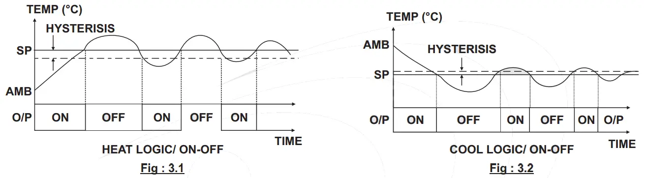
ON-OFF ACTION : In this mode, Output (Relay/SSR) remains ON till actual temperature reaches to the set point value. On reaching to SP, Output turns OFF & remains OFF till actual temperature drops down (in Heat Logic) or raises (in Cool Logic) equal to hysterisis set by user. (As shown in Fig. 3.1 & 3.2)
AUTO TUNING MODE : In this mode, Controller learns the process characteristics by itself and calculates the required P,I & D values. It can be performed at any time after power ON but, it is best to start it when the process is at Ambient temperature in order to minimize overshoot & undershoot. Auto tuning is applied in case of :
- Initial set up for a new process.
- Substantial change in SP from previous auto tuning value.
- Control accuracy is not satisfactory.
If the control performance by using auto-tuning is still unsatisfactory, User can apply further adjustments of P,I & D values as shown in Table:3 below.
Table: 3
| Adjust | Symptom | Solution |
| Proportional Band | Slow Response | Decrease PB |
| Over Shoot or Oscillations | Increase PB | |
| Integral Time | Slow Response | Decrease Int |
| Instability or Oscillation | Increase Int | |
| Derivative Time | Slow Response or Oscillation | Decrease Dt |
| High Over Shoot | Increase Dt |
ABBREVIATION :
C.A. : Control Action
CJC : Cold junction compensation
CM : Common terminal of relay
LWC : Lead wire (Length)- compensation
NC : Normally Close terminal of relay
NO : Normally Open terminal of relay
OP1 : Output 1
SP1 : Set Point Value (set temp.)
PV : Process Value (actual Tamp.)
SSR : Solid State Relay
T/C : Thermocouple
![]() Mfgd by: Innovative Instruments & Controls LLP
Mfgd by: Innovative Instruments & Controls LLP
338, New Sonal Link Service Industrial Premises Co-op Society Ltd,
Building No.2, Link Road, Malad (W), Mumbai – 400064.
Tel: 022-66939916/17/18;
E-mail : [email protected]
Website : www.itherm.co.in https://www.youtube.com/channel/UCzWGtv0HuHUgZR4KKRyKG1w/videos


