
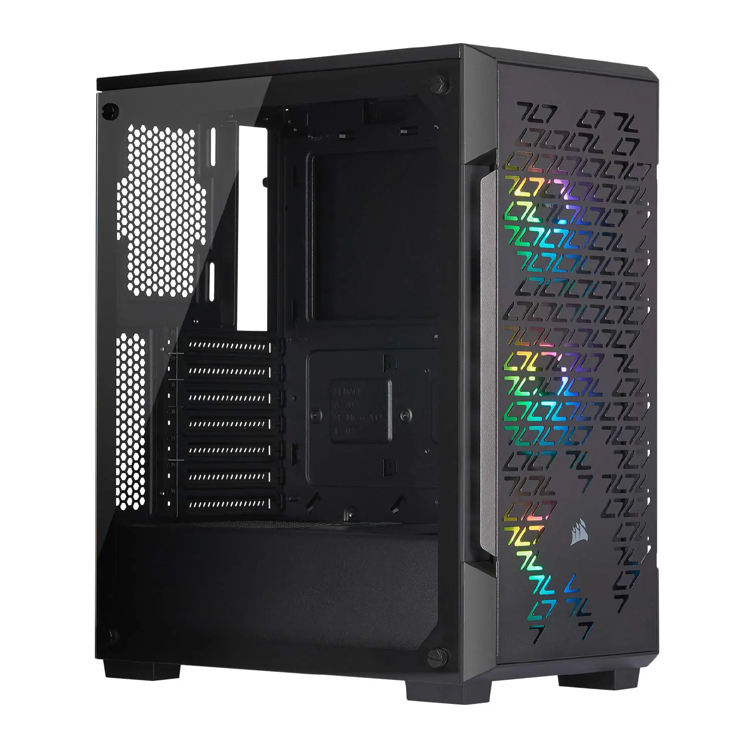
CORSAIR Airflow Tempered Glass Mid-Tower Smart Case
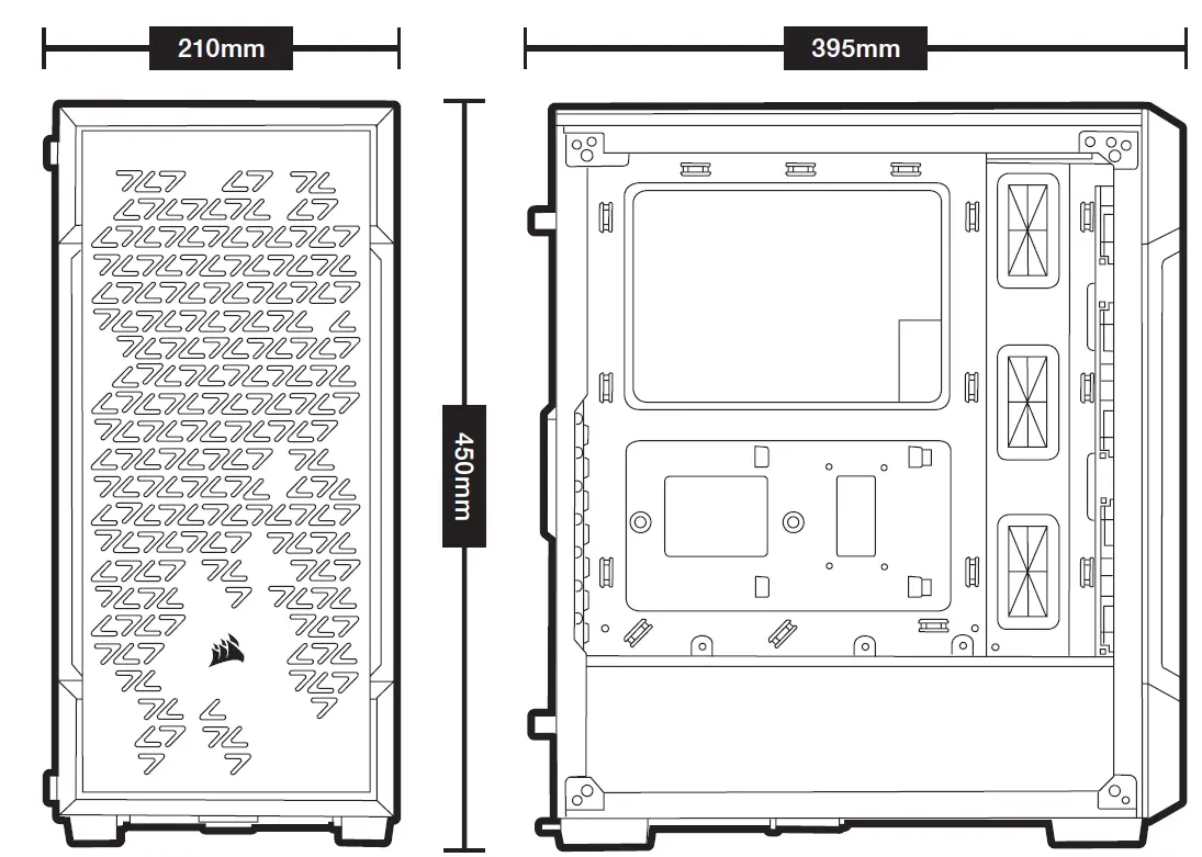
CASE SPECIFICATIONS
Length ………………………………………………………………………………………………………………………………………… 395mm
Width ……………………………………………………………………………………………………………………………………………210mm
Height …………………………………………………………………………………………………………………………………………. 450mm
Maximum GPU length ………………………………………………………………………………………………………………….. 300mm
Maximum CPU height ……………………………………………………………………………………………………………………160mm
Maximum PSU length ……………………………………………………………………………………………………………………180mm
Fan locations:
Front …………………………………………………………………………………………………………………… 3 x 120mm / 2 x 140mm
Top …………………………………………………………………………………………………………………….. 2 x 120mm / 2 x 140mm
Rear ………………………………………………………………………………………………………………………………………..1 x 120mm
Radiator compatibility:
Front ………………………………………………………………………………………………………………………………360mm / 280mm
Top ………………………………………………………………………………………………………………………………………………240mm
Rear ……………………………………………………………………………………………………………………………………………..120mm
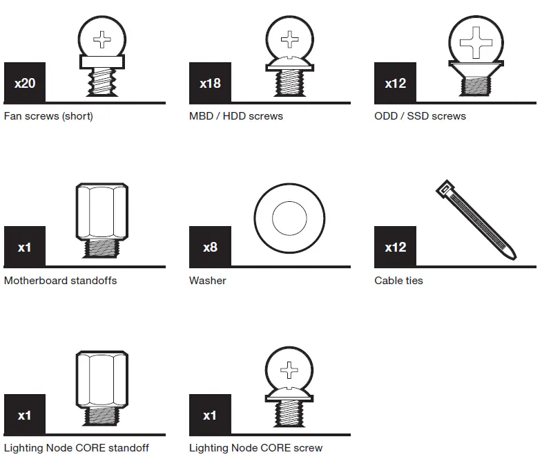
ACCESSORY KIT CONTENTS
CASE FEATURES
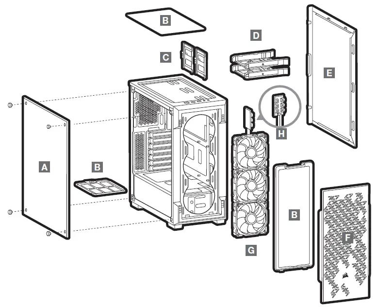
A — TEMPERED GLASS SIDE PANEL
B — DUST FILTERS
C — SSD TRAYS
D — HDD TRAYS
E — SOLID SIDE PANEL
F — FRONT BEZEL
G — 3 x 120mm RGB FANS
H — LIGHTING NODE CORE
How to Assemble
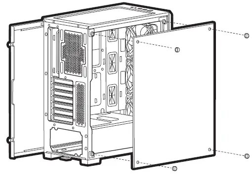
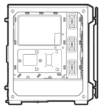
REMOVING THE SIDE PANELS
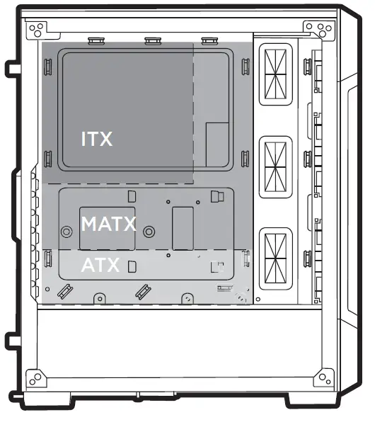
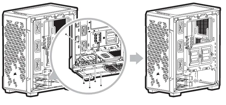
INSTALLING THE MOTHERBOARD
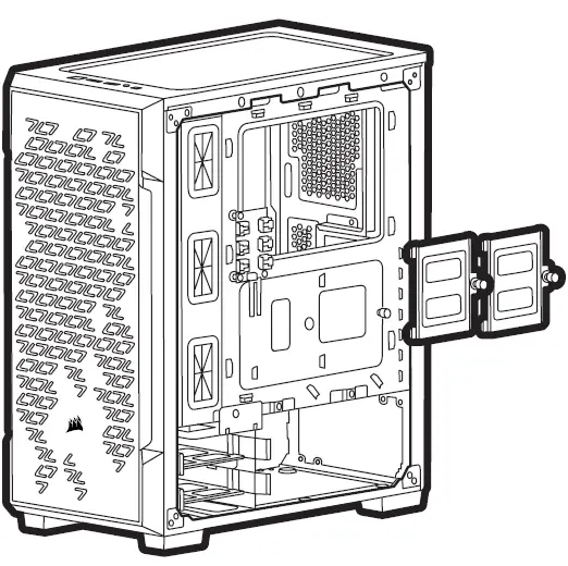
INSTALLING HDDs
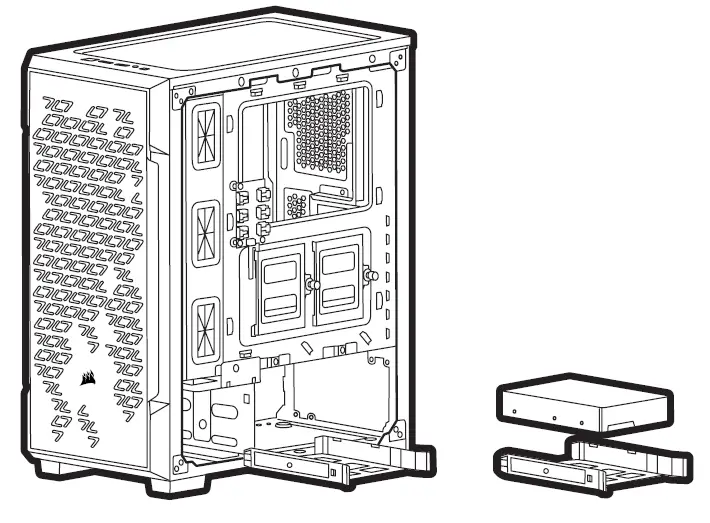
INSTALLING SSDs
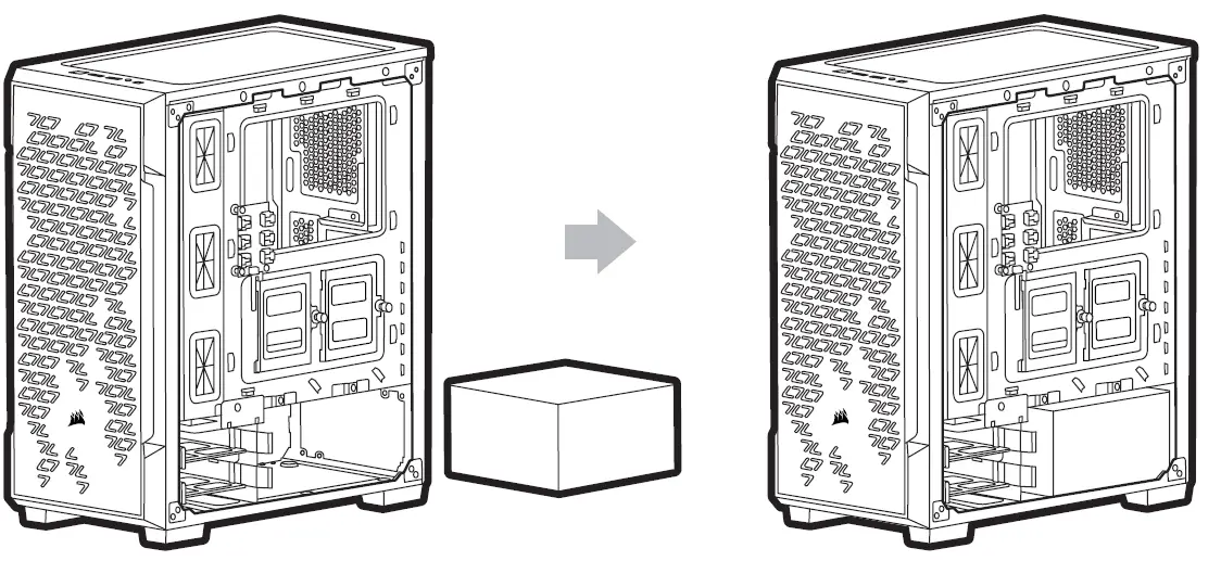
INSTALLING PSU
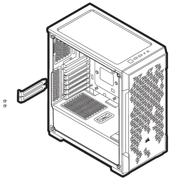
INSTALLING PCI-e CARDS
REMOVING THE FRONT BEZEL
MOVING HDD CAGE
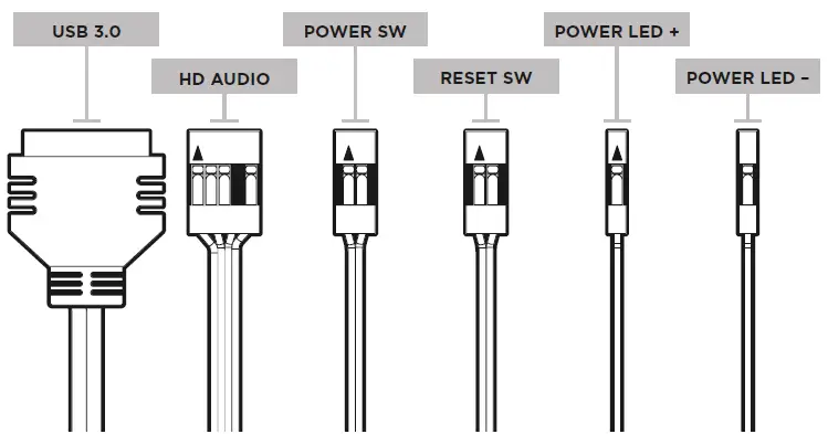
INSTALLING THE FRONT I/O CONNECTORS
CHANGING LOCATION OF THE LIGHTING NODE CORE
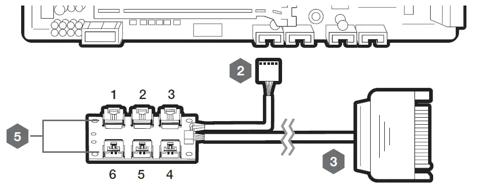
INSTALLING THE LIGHTING NODE CORE
- Turn your system off prior to installing your Lighting Node CORE.
- Plug the 9-pin USB into an available internal USB 2.0 header in your system.
- Plug the SATA connector into an available SATA connector on your PSU.
- The Fan LED wiring must be connected to the fan hub in the order you want the lighting effects to be displayed.
- Fans must start at “1” and continue in series. 1 > 2 > 3 > 4 > 5 > 6
- Any fan not connected in series will break communication and the RGB LED lighting function will not work

FREQUENTLY ASKED QUESTIONS
1. Does the polarity matter with the I/O panel’s power and reset header?
No, only the LED headers.
2. Who should I contact if I received my case damaged or one of the fans is no longer working?
Please go to support.corsair.com and request an RMA so that we can replace the damaged part(s).
3. Where can I mount a fan?
Fan mount locations | |
| Front | 3 x 120mm / 2 x 140mm |
| Top | 2 x 120mm / 2 x 140mm |
| Rear | 1 x 120mm |


