Danfoss EKE 100 Superheat Controller Installation Guide
Introduction
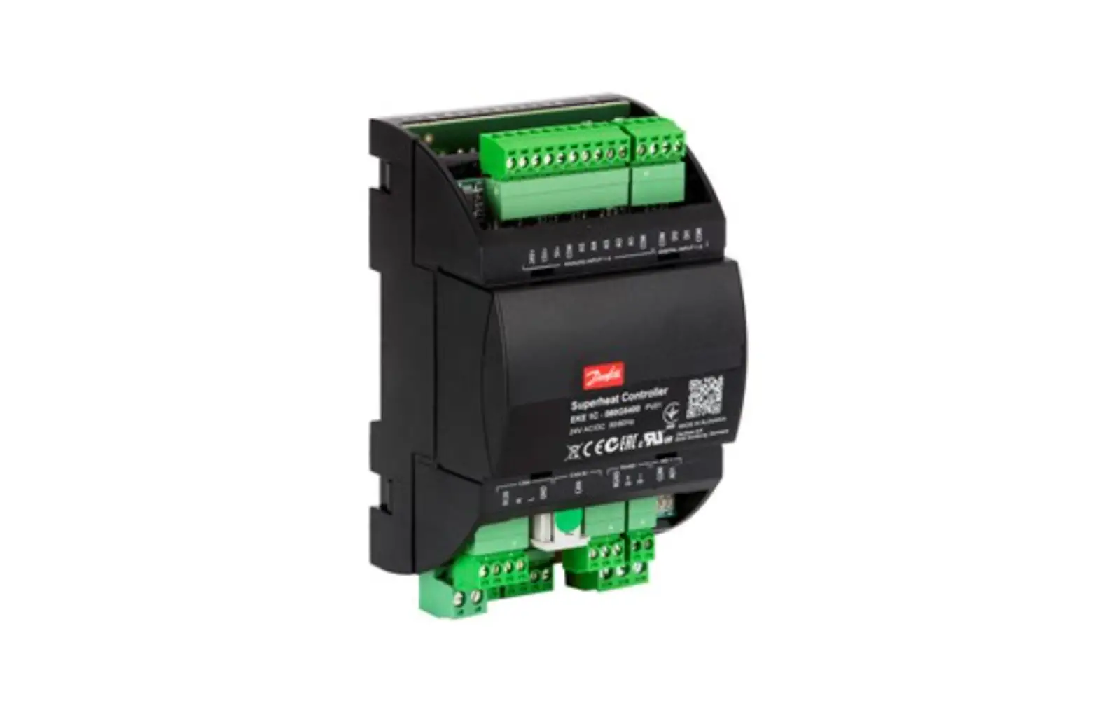
Superheat controller EKE 100 is for use where superheat must be accurately controlled or as driver for stepper motor valves typically in air conditioning, heat pumps, commercial refrigeration, food retailing and industrial application.
Compatible valves: ETS 6/ETS 8M(Bipolar coil)/ETS C/KVS C/ ETS L/ETS 500-800P/ CCMT L/CCMT/CCM/ CTR
Basic application
EKE 100 1Valve SH control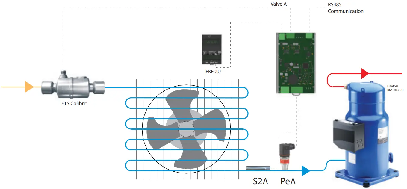
EKE 100 2Valve SH control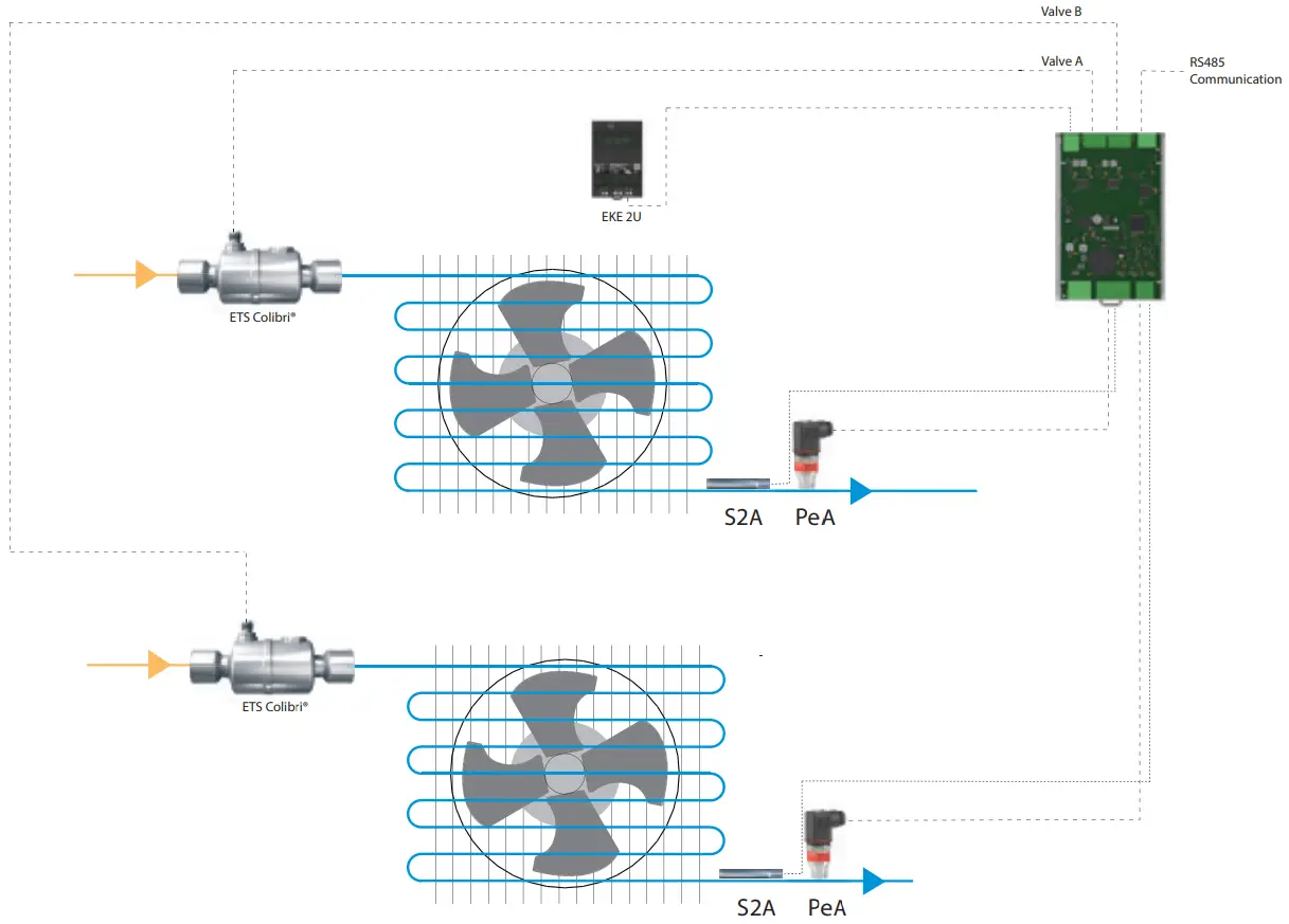
![]() Note:
Note:
For driver function connect analog signal to pressure port(PeA/PeB).
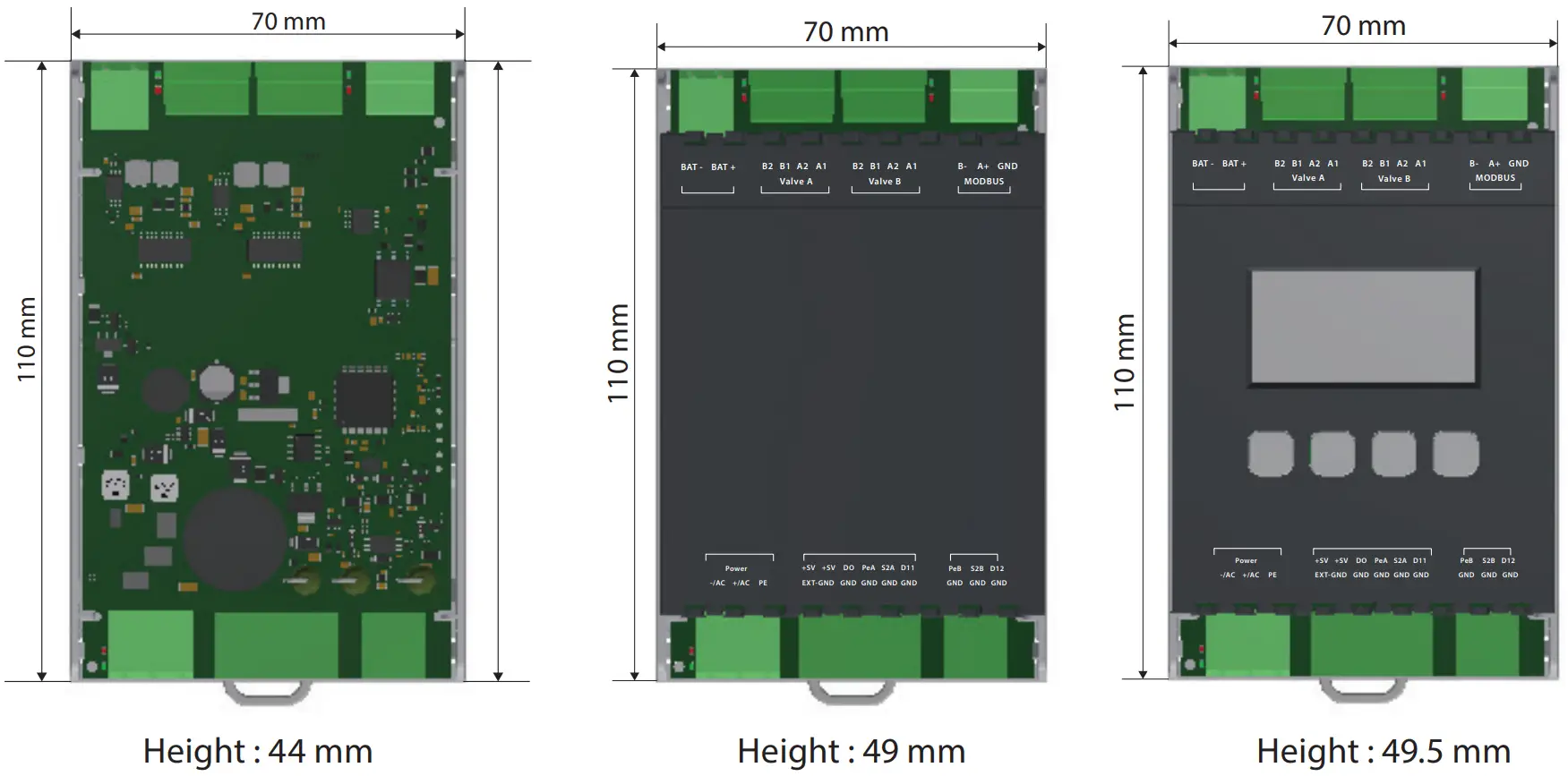
Dimension
Technical specification
| EKE100 1V | EKE100 2V | |
| Code number | IP00: 080G5050 IP20: 080G5051 IP20 W display: 080G5052 | IP00: 080G5055 IP20: 080G5056 IP20 W display: 080G5057 |
| Supply Voltage | 24 V AC / DC +/- 20% , 50 / 60 Hz, class II isolation , No galvanic isolation | 24 V AC / DC +/- 20% , 50 / 60 Hz, class II isolation , No galvanic isolation |
| Battery backup Input (Danfoss recommends EKE 2U) | 24V DC | 24V DC |
| Number of valve outputs | 1 stepper motor valve | 2 stepper motor valves |
| Valve type | Bipolar stepper valve | Bipolar stepper valve |
| Modbus RS485 RTU | Yes (Isolated) | Yes (Isolated) |
| Baud rate (default setting) | 19200 | 19200 |
| Mode (default setting) | 8E1 | 8E1 |
| No of temperature sensors | 1 (S2A) | 2 (S2A,S2B) |
| Type of temperature sensors | PT 1000/NTC 10K | PT 1000/NTC 10K |
| No of Pressure sensors | 1 (PeA) | 2 (PeA,PeB) |
| Type of pressure sensors | Ratiometric 0.5 – 4.5 V DC Current 4-20mA | Ratiometric 0.5 – 4.5 V DC Current 4-20mA |
| No of digital input | 1 (DI1) | 2 (DI1,DI2) |
| Use of digital input | Start/Stop regulation Heat/Cool mode Battery backup signal (SOH) | Start/Stop regulation Heat/Cool mode Battery backup signal (SOH) |
| Digital output | 1 output for EKE 100: D0 (open collector), max sink current 10 mA | 1 output for EKE 100: D0 (open collector), max sink current 10 mA |
| PC suite | Kool Prog | Kool Prog |
| Mounting (DIN rail) | 4 DIN | 4 DIN |
| Storage temperature | -30 – 80 °C / -22 – 176 °F | -30 – 80 °C / -22 – 176 °F |
| Operating temperature | -20 – 70 °C / -4 – 158 °F | -20 – 70 °C / -4 – 158 °F |
| Humidity | <90% RH, non-condensing | <90% RH, non-condensing |
| Enclosure | Available in IP00, IP20 and IP20 with integrated display models | Available in IP00, IP20 and IP20 with integrated display models |
Connection Overview
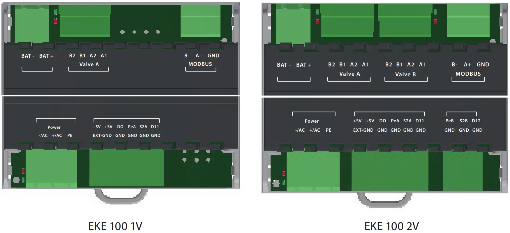
| Port | Description |
| – / AC and + / AC | Power supply |
| PE | Protective earth |
| + 5V | Voltage for pressure probe |
| + 5V | Voltage for pressure probe |
| Ext-GND | Do not use |
| GND | Ground/Comm for I/O signals |
| DO | Digital Output |
| PeA | Pressure signal for A circuit/ Analog signal for A circuit |
| S2A | Temperature signal for A circuit |
| DI1 | Digital Input for A circuit |
| PeB | Pressure signal for B circuit/ Analog signal for B circuit |
| S2B | Temperature signal for B circuit |
| DI2 | Digital Input for B circuit |
| BAT – and BAT + | Battery backup inputs |
| Valve A | Valve port for circuit A |
| Valve B | Valve port for circuit B |
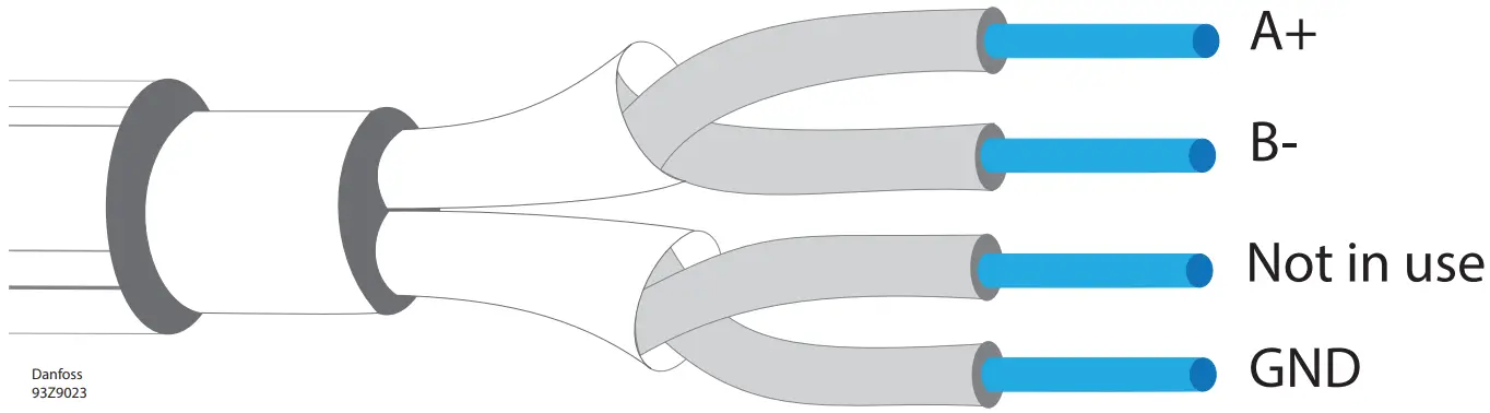
| MODBUS (B-, A+, GND) | Modbus port |
Mounting/Demounting
The unit can be mounted onto a 35 mm DIN rail simply by snapping it into place and securing it with a stopper to prevent sliding. It is demounted by gently pulling the stirrup located in the base of the housing.
Mounting :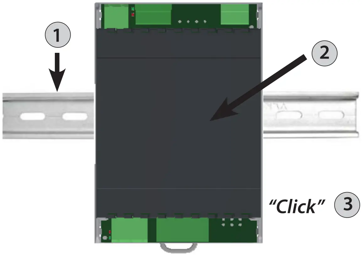
Demounting :
Step 1: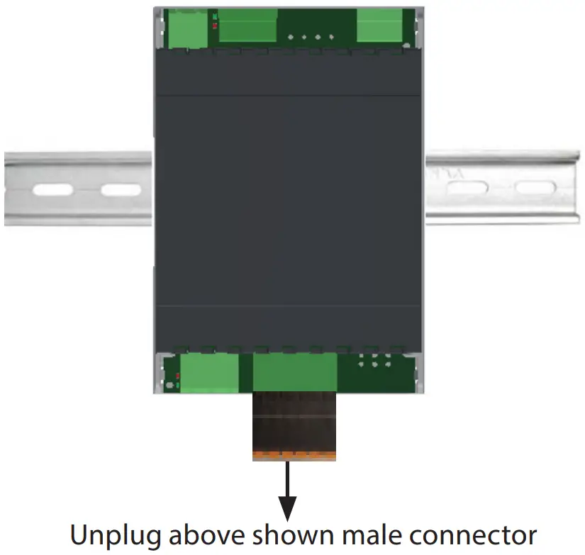
Step 2: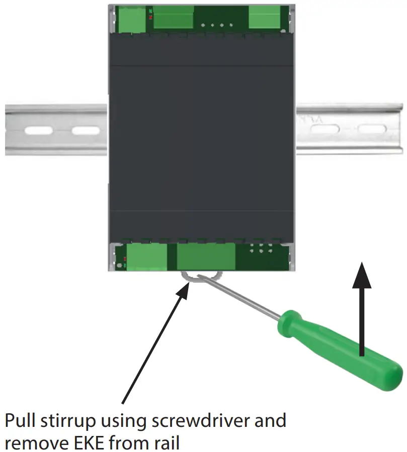
Sensor installation
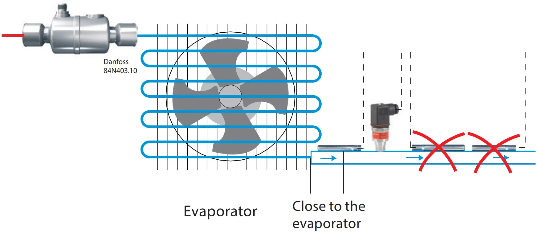
Sensor mounting: Temperature sensor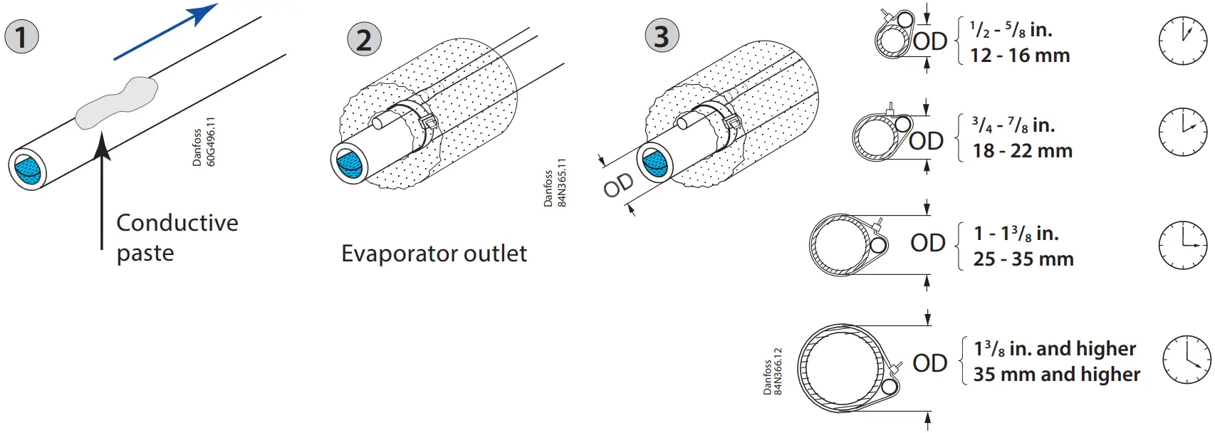
![]() Important Note
Important Note
- Mount the sensor on a clean paint-free surface.
- Remember to use heat conducting paste and insulate the sensor.
- For precise measurements, mount the sensor max. 5 cm from the outlet of the evaporator.

Modbus installation
- For the Modbus cable, it is best to use 24 AWG shielded twisted-pair cable with a shunt capacitance of 16 pF/ft and 100Ω impedance.
- The controller provides an insulated RS485 communication interface which is connected to the RS485 terminals (see connection overview).
- The max. permissible number of devices simultaneously connected to RS485 cable output is 32.
- The RS485 cable is of impedance 120 Ω with maximum length of 1000 m.
- Terminal resistors 120 Ω for terminal devices are recommended at both ends.
- The EKE communication frequency (baud rate) can be one of the following: 9600, 19200 or 38400 baud, default 19200 8E1.
- The default unit address is 1.
- For detailed info on Modbus PNU, check EKE 100 Datasheet

Manual resetting Modbus address
- Remove Supply power from EKE 100
- Connect terminal BAT+ to +5V
- Connect EKE 100 to power
- Now Modbus communication options are reset to factory default(Address 1, 19200 baud, mode 8E1)
Signal Sharing
Power and backup supply sharing
- 1 EKE 100 and 1 EKE 2U can share power supply(AC or DC)
- 2 EKE 100 and 1 EKE 2U can share power supply only with DC
Pressure sensor sharing
- Physical sharing is allowed if used within the same controller and not allowed if 2 or more controllers are used for sharing.
- Modbus sharing is allowed with more than 1 controller.
- Software sharing is allowed within one controller by selecting option Common.
Temperature sensor sharing
- Physical sharing is not allowed.
- Modbus sharing is allowed with more than 1 controller.
- Software sharing is allowed within one controller by selecting option Common.
Cabling
| Stepper valve connector | ETS/KVS/CCM/ CCMT/CTR/ CCMT L(Using Danfoss M12 Cable) | ETS 8M Bipolar | ETS 6 |
| A1 | White | Orange | Orange |
| A2 | Black | yellow | Yellow |
| B1 | Red | Red | Red |
| B2 | Green | Black | Black |
| Not connected | – | – | Grey |
 All valves are driven in a bipolar mode with a 24 V supply chopped to control the current (Current driver).
- The stepper motor is connected to the “Stepper Valve” terminals (see terminal assign ment) with a standard M12 connection cable.
- To configure stepper motor valves other than Danfoss stepper motor valves, the correct valve parameters must be set as described in the Valve configuration section by selecting user defined valve.
| Cable length | Wire size min/max (mm2) | |
| Power supply | Max 5m | 0.2/2.5 |
| Analog inputs | Max 10m | 0.14/1.5 |
| Sensor | Max 10m | – |
| Stepper valve | Max 30m | 0.14/1.5 |
| Digital input | Max 10m | 0.14/1.5 |
| Digital output | – | 0.2/2.5 |
- The max. cable distance between the controller and the valve depends on many factors like shielded/unshielded cable, the wire size used in the cable, the output power for the controller and the EMC.
- Keep controller and sensor wiring well separated from mains wiring.
- Connecting sensor wires more than specified length may decrease the accuracy of measured values.
- Separate the sensor and digital input cables as much as possible(at least 10cm) from the power cables to the loads to avoid possible electromagnetic disturbances. Never lay power cables and probe cables in the same conduit (including those in electrical panels)
LED Alarm and Warning
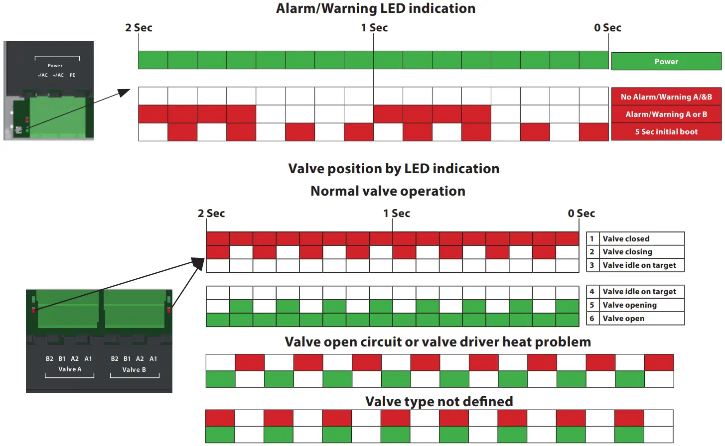
General features and warning
Plastic housing features
- DIN rail mounting complying with EN 60715
- Self-extinguishing V0 according to IEC 60695-11-10 and glowing/hot wire test at 960 °C according to IEC 60695-2-12
Other features
- To be integrated in Class I and/or II appliances
- Index of protection: IP00 or IP20 on product, depending on sales number
- Period of electric stress across insulating parts: long – Suitable for using in a normal pollution environment
- Category of resistance to heat and fire: D
- Immunity against voltage surges: category II
- Software class and structure: class A
CE Compliance
- Operating conditions CE: -20T70, 90% RH non-condensing
- Storage conditions: -30T80, 90% RH non-condensing
- Low voltage guideline: 2014/35/EU
- Electromagnetic compatibility EMC: 2014/30/EU and with the following norms:
- EN61000-6-1, (Immunity standard for residential, commercial, and light-industrial environments)
- EN61000-6-2, (Immunity standard for industrial environments)
- EN61000-6-4, (emission standard for industrial environments)
- EN60730 (Automatic electrical controls for household and similar use)
General warnings
- Every use that is not described in this manual is considered incorrect and is not authorized by the manufacturer
- Verify that the installation and operating conditions of the device respect those specified in the manual, especially concerning the supply voltage and environmental conditions
- All service and maintenance operations must therefore be performed by qualified personnel
- The device must not be used as a safety device
- Liability for injury or damage caused by the incorrect use of the device lies solely with the user
Installation warnings
- Recommended mounting position: vertical
- Installation must comply with local standards and legislation
- Before working on the electrical connections, disconnect the device from the main power supply
- Before carrying out any maintenance operations on the device, disconnect all electrical connections – For safety reasons the appliance must be fitted inside an electrical panel with no live parts accessible
- Do not expose the device to continuous water sprays or to a relative humidity greater than 90%.
- Avoid exposure to corrosive or pollutant gases, natural elements, environments where explosives or mixes of flammable gases are present, dust, strong vibrations or shock, large and rapid fluctuations in ambient temperature that might cause condensation in combination with high humidity, strong magnetic and/or radio interference (e.g., transmitting antenna)
- Use cable ends suitable for the corresponding connectors. After tightening connector screws, tug the cables gently to check their tightness – Minimize the length of probe and digital input cables as much as possible, and avoid spiral routes around power devices. Separate from inductive loads and power cables to avoid possible electromagnetic noises – Avoid touching or nearly touching the electronic components on the board to avoid electrostatic discharges
- Use appropriate data communication cables. Refer to the EKE data sheet for the kind of cable to be used and setup recommendations
- Minimize the length of probe and digital input cables as much as possible and avoid spiral routes around power devices. Separate from inductive loads and power cables to avoid possible electro magnetic noises
- Avoid touching or nearly touching the electronic components fitted on the board to avoid electrostatic discharges
Product warnings
- Use a class II power supply.
- Connecting any EKE inputs to mains voltage will permanently damage the controller.
- Battery Backup terminals does not generate power to recharge a device connected.
- Battery backup – the voltage will close the stepper motor valves if the controller loses its supply voltage.
- Do not connect an external power supply to the digital input DI terminals to avoid damaging the controller.
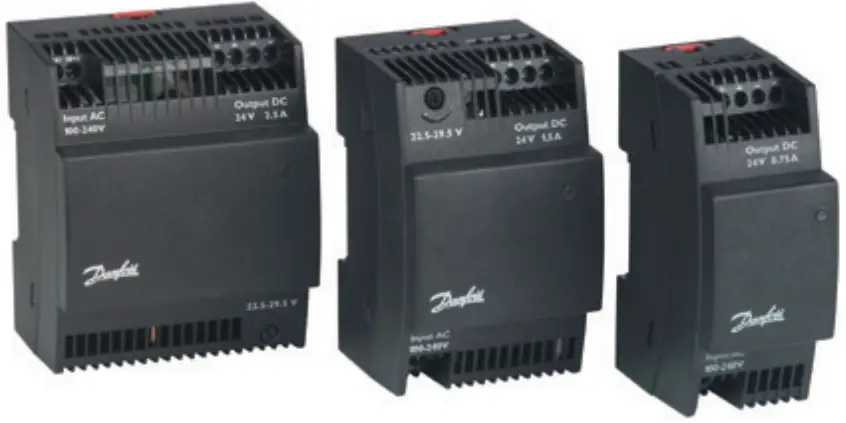
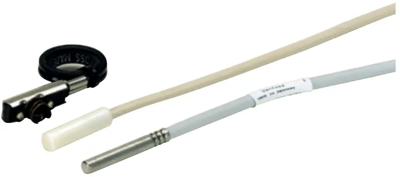
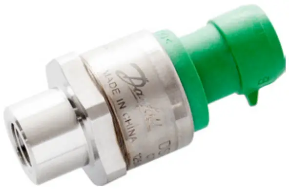
| Power supply | Temperature sensor | Pressure transducer |
|
|
|
| AK-PS Input: 100 – 240 V AC, 45 – 65 Hz Output: 24 V DC: available with 18 VA, 36 VA and 60 VA ACCTRD Input: 230 V AC, 50 – 60 Hz Output: 24 V AC, available with 12 VA, 22 VA and 35 VA | PT 1000 AKS is a High precision temp. sensor AKS 11 (preferred), AKS 12, AKS 21 ACCPBT PT1000 NTC sensors EKS 221 ( NTC-10 Kohm) MBT 153 ACCPBT NTC Temp probe (IP 67 /68) | DST / AKS Pressure Tranducer Available with ratiometric and 4 – 20 mA. NSK Ratiometric pressure probe XSK Pressure probe 4 – 20 mA |
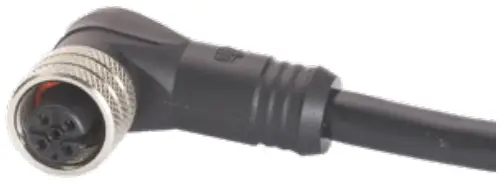
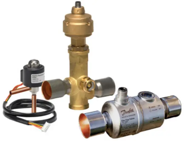
| Stepper motor valves | M12 cable | Backup power module |
|  |
|
| EKE is compatible with Danfoss stepper motor valves i.e Danfoss ETS 6, ETS, KVS, ETS Colibri®, KVS colibri®, CTR, CCMT, ETS 8M, CCMT L, ETS L | M12 Angle cable to connect Danfoss stepper motor valve and EKE controller | EKE 2U energy storage device for emergency valve shutdown during power outage. |

Any information, including, but not limited to information on selection of product, its application or use, product design, weight, dimensions, capacity or any other technical data in product manuals, catalogues descriptions, advertisements, etc. and whether made available in writing, orally, electronically, online or via download, shall be considered informative, and is only binding if and to the extent, explicit reference is made in a quotation or order confirmation. Danfoss cannot accept any responsibility for possible errors in catalogues, brochures, videos and other material. Danfoss reserves the right to alter its products without notice. This also applies to products ordered but not delivered provided that such alterations can be made without changes to form, fit or function of the product.
All trademarks in this material are property of Danfoss A/S or Danfoss group companies. Danfoss and the Danfoss logo are trademarks of Danfoss A/S. All rights reserved.


