![]() ENGINEERING
ENGINEERING
TOMORROW
Installation Guide
Case controller
Type EKC 223
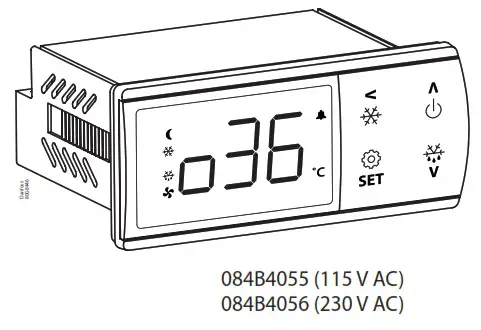
Identification
Application
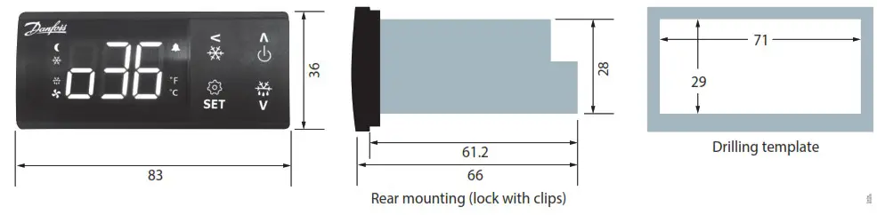
Dimensions
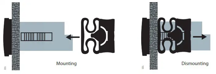
Mounting
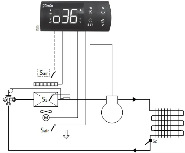
Wiring diagrams
| Application | Wiring diagrams |
| 1 | 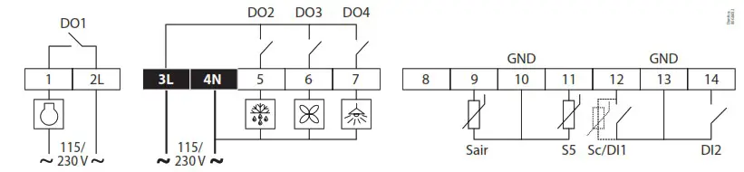 |
| 2 | 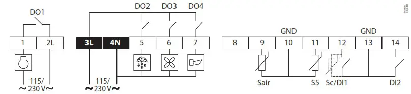 |
| 3 | 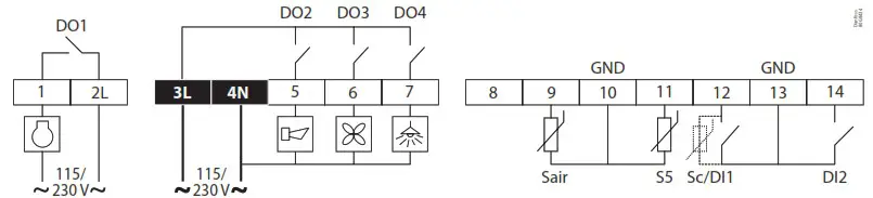 |
| 4 | 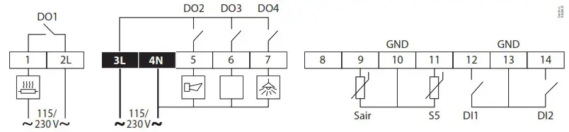 |
Note: Power connectors: wire size = 0.5 – 1.5 mm 2 , max. tightening torque = 0.4 Nm Low voltage signal connectors: wire size = 0.15 – 1.5 mm 2 , max. tightening torque = 0.2 Nm 2L and 3L must be connected to the same phase.
Data communication
| Installation | Wiring |
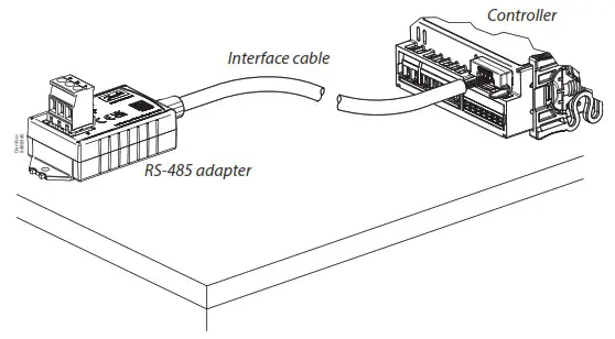 The EKC 22x controller can be integrated into a Modbus network via the RS-485 adapter (EKA 206) using an interface cable (080N0327). For installation details please refer to installation guide for EKA 206 – RS485 adapter. | 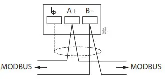 |
Technical data
| Features | Description |
| Purpose of control | Operating temperature sensing control suitable for incorporation into commercial air-conditioning and refrigeration applications |
| Construction of control | Incorporated control |
| Power supply | 084B4055 – 115 V AC / 084B4056 – 230 V AC 50/60 Hz, galvanic isolated low voltage regulated power supply |
| Rated power | Less than 0.7 W |
| Inputs | Sensor inputs, Digital inputs, Programming key Connected to SELV limited energy <15 W |
| Allowed sensor types | NTC 5000 Ohm at 25 °C, (Beta value=3980 at 25/100 °C – EKS 211) NTC 10000 Ohm at 25 °C, (Beta value=3435 at 25/85 °C – EKS 221) PTC 990 Ohm at 25 °C, (EKS 111) Pt1000, (AKS 11, AKS 12, AKS 21) |
| Accuracy | Measuring range: -40 – 105 °C (-40 – 221 °F) |
| Controller accuracy: ±1 K below -35 °C, ±0.5 K between -35 – 25 °C, ±1 K above 25 °C | |
| Type of action | 1B (relay) |
| Output | DO1 – Relay 1: 16 A, 16 (16) A, EN 60730-1 10 FLA / 60 LRA at 230 V, UL60730-1 16 FLA / 72 LRA at 115 V, UL60730-1 |
| DO2 – Relay 2: 8 A, 2 FLA / 12 LRA, UL60730-1 8 A, 2 (2 A), EN60730-1 | |
| DO3 – Relay 3: 3 A, 2 FLA / 12 LRA, UL60730-1 3 A, 2 (2 A), EN60730-1 | |
| DO4 – Relay 4: 2 A | |
| Display | LED display, 3 digits, decimal point and multi-function icons, °C + °F scale |
| Operating conditions | -10 – 55 °C (14 – 131 °F), 90% Rh |
| Storage conditions | -40 – 70 °C (-40 – +158 °F), 90% Rh |
| Protection | Front: IP65 (Gasket integrated) Rear: IP00 |
| Environmental | Pollution degree II, non-condensing |
| Overvoltage category | II – 230 V supply version – (ENEC, UL recognized) III – 115 V supply version – (UL recognized) |
| Resistance to heat and fire | Category D (UL94-V0) Temperature for ball pressure test statement According to Annex G (EN 60730-1) |
| EMC category | Category I |
| Approvals | UL recognition (US & Canada) (UL 60730-1) CE (LVD & EMC Directive) EAC (GHOST) UKCA UA CMIM ROHS2.0 Hazloc approval for flammable refrigerants (R290/R600a). R290/R600a end-use applications employing in accordance with the IEC60079-15 requirements. |
Display operation
The buttons on the front of the display can be operated with short and long (3s) presses.
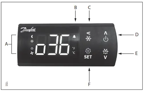
| A | Status indication: LEDs light up at ECO/Night mode, cooling, defrost and fan running. |
| B | Alarm indication: Alarm icon flashes in case of an alarm. |
| C | Short press = Navigate back Long press = Initiate pulldown cycle. Display will show “Pod” to confirm start. |
| D | Short press = Navigate up Long press = Switch controller ON/OFF (setting r12 Main switch in ON/OFF position) |
| E | Short press = Navigate down Long press = Start defrosting cycle. Display will show the code “-d-“ to confirm start. |
| F | Short press = Change set point Long press = Go to parameter menu |
Factory resetting
The controller can be set back to factory settings by using the following procedure:
- Power OFF controller
- Keep up “∧” and down “∨” arrow buttons pressed while reconnecting the supply voltage
- When the code “Face” is shown in the display, select “yes”
Note: The OEM factory setting will either be the Danfoss factory settings or a user defined factory setting if one has been made. The user can save his setting as OEM factory setting via parameter o67.
Display codes
| Display code | Description |
| -d- | Defrost cycle is in progress |
| Pod | A temperature pulldown cycle has been initiated |
| Err | The temperature cannot be displayed due to a sensor error |
| — | Shown in top of display: The parameter value has reached max. Limit |
| — | Shown in bottom of display: The parameter value has reached min. Limit |
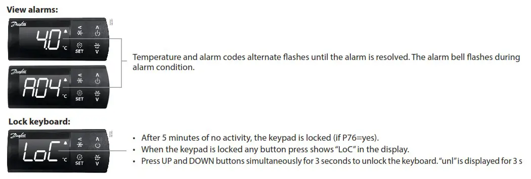
| Lock | The display keyboard is locked |
| Null | The display keyboard has been unlocked |
| PS | The access code is required to enter the parameter menu |
| Ax/Ext | Alarm or error code flashing with normal temp. readout |
| OFF | Control is stopped as r12 Main switch is set OFF |
| On | Control is started as r12 Main switch is set ON (code shown in 3 seconds) |
| Face | The controller is reset to factory setting |
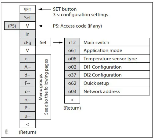
The parameter menu is accessed by pressing the “SET” key for 3 seconds. If an access protection code “o05” has been defined the display will ask for the access code by showing the code “PS”. Once the access code has been provided by the user, the parameter list will be accessed.
Get a good start
With the following procedure you can start regulation very quickly:
- Press the “SET” button for 3 seconds and access the parameter menu (display will show “in”)
- Press the down button “∨” to go to “tcfg” menu (display will show “tcfg”)
- Press the right/“>” key to open the configuration menu (display will show r12)
- Open the “r12 Main switch” parameter and stop control by setting it OFF (Press SET)
- Open the “o61 application mode” and select the needed application mode (Press SET)
- Open the “o06 Sensor type” and select the temperature sensor type used (n5=NTC 5 K, n10=NTC 10 K, Pct.=PTC, Pt1=Pt1000) – (Press “SET”).
- Open the “o02 DI1 Configuration” and select the function associated to digital input 1 (Please refer to parameter list) – (Press “SET”).
- Open the “o37 DI2 Configuration” and select the function associated to digital input 2 (Please refer to parameter list) – (Press “SET”).
- Open the “o62 Quick setting” parameter and select the presetting that fits with the application in use (please refer to preset table below) – (Press “SET”).
- Open the “o03 Network address” and set the Modbus address if required.
- Navigate back to parameter “r12 Main switch” and set it in “ON” position to start control.
- Go through the entire parameter list and change the factory settings where needed.
Selection of quick settings
| Quick setting | 1 | 2 | 3 | 4 | 5 | 6 | 7 |
| Cabinet MT Natural def. Stop on time | Cabinet MT El. def. Stop on time | Cabinet MT El. def. Stop on temp | Cabinet LT El. def. Stop on temp | Room MT El. def. Stop on time | Room MT El. def. Stop on temp | Room LT El. def. Stop on temp | |
| r00 Cut-out | 4 °C | 2 °C | 2 °C | -24 °C | 6 °C | 3 °C | -22 °C |
| r02 Max Cut-out | 6 °C | 4 °C | 4 °C | -22 °C | 8 °C | 5 °C | -20 °C |
| r03 Min Cut-out | 2 °C | 0 °C | 0 °C | -26 °C | 4 °C | 1 °C | -24 °C |
| A13 Highly Air | 10 °C | 8 °C | 8 °C | -15 °C | 10 °C | 8 °C | -15 °C |
| Al 4 Lowly Air | -5 °C | -5 °C | -5 °C | -30 °C | 0 °C | 0 °C | -30 °C |
| d01 Def. Method | Natural | Electrical | Electrical | Electrical | Electrical | Electrical | Electrical |
| d03 Def.lnterval | 6 hour | 6 hour | 6 hour | 12 hour | 8 hour | 8 hour | 12 hour |
| d10 DefStopSens. | Time | Time | S5 Sensor | 55 Sensor | Time | S5 Sensor | S5 Sensor |
| o02 DI1 Config. | Door fct. | Door fct. | Door fct. |
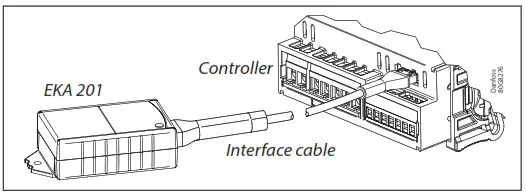
Programming key
Programming controller with Mass Programming Key (EKA 201)
- Power up the controller. Make sure the controllers is connected to mains.
- Connect the EKA 201 to the controller using the respective controller interface cable.
- The EKA 201 will automatically start the programming process.
Parameter list
| Code | Short text manual | Min. | Max. | 2 | Unit | R/W | EKC 224 Appl. | |||
| 1 | 2 | 3 | 4 | |||||||
| CFg | Configuration | |||||||||
| r12 | Main switch (-1=service /0=OFF / 1=0N) | -1 | 1 | 0 | R/W | * | * | * | * | |
| o61¹) | Selection of application mode (1)API: Cmp/Def/Fan/Light (2)AP2: Cmp/Def/Fan/Alarm (3)AP3: Cmp/ Al/F an/Light (4)AP4: Heat/Alarm/Light | 1 | 4 | R/W | * | * | * | * | ||
| o06¹) | Sensor type selection (0) n5= NTC 5k, (1) n10 = NTC 10k, (2)Pt = Pt1003, (3) Pct. = PTC 1000 | 0 | 3 | 2 | R/W | * | * | * | * | |
| o02¹) | Dell configuration (0) of=not used (1) SD=status, (2) doo–door function, (3) do=door alarm, (4) SCH=main switch, (5)nigh=day/night mode, (6) rd=reference displacement (7) EAL=external alarm, (8) def.=defrost, (9) Pod =pull I down, (10) Sc=condenser sensor | 0 | 10 | 0 | R/W | * | * | * | * | |
| 037¹) | DI2 configuration (0) of=not used (1) SD=status, (2) doo–door function, (3) do=door alarm, (4) SCH=main switch, (5) nigh=day/night mode, (6) sled=ref refence displacement (7) EAL=external alarm, (8) def.=defrost, (9) Pod=pull down | 0 | 9 | 0 | R/W | * | * | * | * | |
| o62¹) | Quick presetting of primary parameters 0= Not used 1 = MT, Natural defrost, stop on time 2 = MT, El defrost, stop on time 3= MT, El defrost, stop on temp. 4 = LT, El defrost stop on temp. 5 = Room, MT, El defrost, stop on time 6= Room, MT, El defrost, stop on temp. 7= Room, LT, El defrost, stop on temp. | 0 | 7 | 0 | RIW | * | * | * | ||
| o03¹) | Network address | 0 | 247 | 0 | R/W | * | * | * | * | |
| r– | Thermostat | |||||||||
| r00 | Temperature setpoint | r03 | r02 | 2.0 | °C | R/W | * | * | * | * |
| r01 | Differential | 0.1 | 20.0 | 2.0 | K | R/W | * | * | * | * |
| r02 | Max. limitation of setpoint setting | r03 | 105.0 | 50.0 | °C | R/W | * | * | * | * |
| r03 | Min. limitation of setpoint setting | –40.0 | r02 | –35.0 | °C | R/W | * | * | * | * |
| r04 | Adjustment of the display’s temperature readout | –10.0 | 10.0 | 0.0 | K | R/W | * | * | * | * |
| r05 | Temperature unit rC / °F) | 0/C | 1/F | 0/C | R/W | * | * | * | * | |
| r09 | Correction of the signal from Sair sensor | –20.0 | 20.0 | 0.0 | °C | R/W | * | * | * | * |
| r12 | Main switch (-1=service /0=OFF / 1=0N) | -1 | 1 | 0 | R/W | * | * | * | * | |
| r13 | Displacement of reference during night operation | –50.0 | 50.0 | 0.0 | K | R/W | * | * | * | |
| r40 | Thermostat reference displacement | –50.0 | 20.0 | 0.0 | K | R/W | * | * | * | * |
| r96 | Pull-down duration | 0 | 960 | 0 | min | R/W | * | * | * | |
| r97 | Pull-down limit temperature | –40.0 | 105.0 | 0.0 | °C | R/W | * | * | * | |
| A- | Alarm settings | |||||||||
| A03 | Delay for temperature alarm (short) | 0 | 240 | 30 | min | R/W | * | * | * | * |
| Al2 | Delay for temperature alarm at pulldown (long) | 0 | 240 | 60 | min | R/W | * | * | * | * |
| A13 | High alarm limit | –40.0 | 105.0 | 8.0 | °C | R/W | * | * | * | * |
| A14 | Low alarm limit | –40.0 | 105.0 | –30.0 | °C | R/W | * | * | * | * |
| A27 | Alarm delay Dll | 0 | 240 | 30 | min | R/W | * | * | * | * |
| A28 | Alarm delay DI2 | 0 | 240 | 30 | min | R/W | * | * | * | * |
| A37 | Alarm limit for condenser temperature alarm | 0.0 | 200.0 | 80.0 | °C | R/W | * | * | * | |
| A54 | Limit for condenser block alarm and comp. Stop | 0.0 | 200.0 | 85.0 | °C | R/W | * | * | * | |
| A72 | Voltage protection enable | 0/No | 1/Yes | 0/No | R/W | * | * | * | ||
| A73 | Minimum cut-in voltage | 0 | 270 | 0 | Volt | R/W | * | * | * | |
| A74 | Minimum cut-out voltage | 0 | 270 | 0 | Volt | R/W | * | * | * | |
| A75 | Maximum cut-in voltage | 0 | 270 | 270 | Volt | R/W | * | * | * | |
| d— | Defrost | |||||||||
| d01 | Defrost method (0) non =None, (1) not = Natural, (2) E1 = Electrical, (3) gas = Hot gas | 0 | 3 | 2 | R/W | * | * | * | ||
| d02 | Defrost stop temperature | 0.0 | 50.0 | 6.0 | °C | R/W | * | * | * | |
| d03 | Interval between defrost starts | 0 | 240 | 8 | hour | R/W | * | * | * | |
| d04 | Max. defrost duration | 0 | 480 | 30 | min | R/W | * | * | * | |
| d05 | lime offset for start of first defrost at start-up | 0 | 240 | 0 | min | R/W | * | * | * | |
| d06 | Drip off time | 0 | 60 | 0 | min | R/W | * | * | * | |
| d07 | Delay for fan start after defrost | 0 | 60 | 0 | min | R/W | * | * | * | |
| d08 | Fan start temperature | -40.0 | 50.0 | -5.0 | °C | R/W | * | * | * | |
| d09 | Fan operation during defrost | 0/Off | 1/ On | 1/On | R/W | * | * | * | ||
| d10″ | Defrost sensor (0=time, 1=Sair, 2=55) | 0 | 2 | 0 | R/W | * | * | * | ||
| d18 | Max. comp. runtime between two defrosts | 0 | 96 | 0 | hour | R/W | * | * | * | |
| d19 | Defrost on demand – 55 temperatures permitted variation during frost build-up. On central plant choose 20 K (=off) | 0.0 | 20.0 | 20.0 | K | R/W | * | * | * | |
| d30 | Defrost delay after pull-down (0 = OFF) | 0 | 960 | 0 | min | R/W | * | * | * | |
| F— | Fan | |||||||||
| F1 | Fan at stop of compressor (0) FFC = Follow comp., (1) Foo = ON, (2) FPL = Fan pulsing | 0 | 2 | 1 | R/W | * | * | * | ||
| F4 | Fan stop temperature (55) | -40.0 | 50.0 | 50.0 | °C | R/W | * | * | * | |
| F7 | Fan pulsing ON cycle | 0 | 180 | 2 | min | R/W | * | * | ||
| F8 | Fan pulsing OFF cycle | 0 | 180 | 2 | min | R/W | * | * | * | |
| c— | Compressor | |||||||||
| c01 | Min. ON-time | 0 | 30 | 1 | min | R/W | * | * | * | |
| c02 | Min. OFF-time | 0 | 30 | 2 | min | R/W | * | * | * | |
| c04 | Compressor OFF delay at door open | 0 | 900 | 0 | sec | R/W | * | * | * | |
| c70 | Zero crossing selection | 0/No | 1/Yes | 1/Yes | R/W | * | * | * | ||
| o— | Miscellaneous | |||||||||
| o01 | Delay of outputs at start-up | 0 | 600 | 10 | sec | R/W | * | * | * | * |
| o2″ | DI1 configuration (0) oFF=not used (1) Sdc=status, (2) doo=door function, (3) doA=door alarm, (4) SCH=main switch (5) nig=day/night mode, (6) rFd=reference displacement, (7) EAL=external alarm, (8) dEF=clefrost, (9) Pud=pull down, (10) Sc=condenser sensor | 0 | 10 | 0 | R/W | * | * | * | * | |
| o3″ | Network address | 0 | 247 | 0 | R/W | * | * | * | * | |
| 5 | Access code | 0 | 999 | 0 | R/W | * | * | * | * | |
| 006″ | Sensor type selection (0) n5 = NTC 5k, (1) n10 = NTC 10k, (2)Pt = Pt1000, (3) Ptc = PTC 1000 | 0 | 3 | 2 | R/W | * | * | * | * | |
| o15 | Display resolution (0) 0.1, (1)0.5, (2)1.0 | 0 | 2 | 0 | R/W | * | * | * | * | |
| o16 | Max. standby lime after coordinated defrost | 0 | 360 | 20 | min | R/W | * | * | * | |
| o37′. | Dl? configuration (0) of=not used (1) Sack=status, (2) doo=door function, (3) do=door alarm, (4) SCH=main switch, (5) nigh=day/night mode, (6) rd=ref Terence displacement, (7) EAL=external alarm, (8) def.=def ran, (9) Pod=pull I down | 0 | 9 | 0 | R/W | * | * | * | * | |
| o38 | Configuration of light function (0) on=always on, (1) Dan=day/night (2) doo=based on door action, (3) nets = Network | 0 | 3 | 1 | R/W | * | * | * | ||
| o39 | Light control via network (only if o38=3(.NET)) | 0/Off | 1/ On | 1/On | R/W | * | * | * | ||
| 061″ | Selection of application mode (1) API: Cmp/Def/Fan/Light (2) AP2: Cmp/Def/Fan/A 6 rim (3) AP3: Cmp/Al/Fan/Light (4) AP4: Heat/Alarm/Light | 1 | 4 | 1 | R/W | * | * | * | * | |
| o62’s | Quick presetting of primary parameters 0= Not used 1= MT, Natural defrost, stop on time 2 = MT, El defrost, stop on time 3= MT, El defrost, stop on temp. 4= LT, El defrost stop on temp 5 = Room, MT, El defrost, stop on time 6= Room, MT, El defrost, stop on temp. 7= Room, LT, El defrost, stop on temp. | 0 | 7 | 0 | R/W | * | * | * | ||
| 67 | Replace the controllers factory settings with the present settings | 0/No | 1/Yes | 0/No | R/W | * | * | * | * | |
| 91 | Display at defrost (0) Air=Sari temperature / (1) Fret=freeze temperature/ (2) -d-r-v-d-s is displayed | 0 | 2 | 2 | R/W | * | * | * | ||
| P— | Polarity | |||||||||
| P75 | Invert alarm relay (1) = Invert relay action | 0 | 1 | 0 | R/W | * | * | * | ||
| P76 | Keyboard lock enable | 0/No | 1/Yes | 0/No | R/W | * | * | * | * | |
| u— | Service | |||||||||
| u00 | Control state 50: Normal, 51: Wart after defrosting. 52: Min ON timer, 53: Min OFF timer, 54: Drip oft 510: r12 Main switch set OFF, 511: Thermostat cut-out 514: Defrosting, $15: Fan delay, 517: Door open, 520: Emergency cooling, 525: Manual control, 530: Pulldown cycle, 532: Power up delay, S33: Heating | 0 | 33 | 0 | R | * | * | * | * | |
| u01 | Sari Air temperature | -100.0 | 200.0 | 0.0 | °C | R | * | * | * | * |
| u09 | S5 Evaporator temperature | -100.0 | 200.0 | 0.0 | °C | R | * | * | * | * |
| u10 | Status of DI1 input | 0/Off | 1/ On | 0/Off | R | * | * | * | * | |
| u13 | Night condition | 0/Off | 1/ On | 0/Off | R | * | * | * | * | |
| u37 | Status of DI2 input | 0/Off | 1/ On | 0/Off | R | * | * | * | * | |
| u28 | Actual thermostat reference | -100.0 | 200.0 | 0.0 | R | * | * | * | * | |
| u58 | Compressor/ Liquid line solenoid valve | 0/Off | 1/ On | 0/Off | R | * | * | * | ||
| u59 | Fan relay | 0/Off | 1/ On | 0/Off | R | * | * | * | ||
| u60 | Defrost relay | 0/Off | 1/ On | 0/Off | R | * | * | |||
| u62 | Alarm relay | 0/Off | 1/ On | 0/Off | R | * | * | * | ||
| u63 | Light relay | 0/Off | 1/ On | 0/Off | R | * | * | * | ||
| LSO | Firmware version readout | R | * | * | * | * | ||||
| u82 | Controller code no. | R | * | * | * | * | ||||
| u84 | Heat relay | 0/Off | 1/ On | 0/Off | R | * | ||||
| U09 | Sc Condenser temperature | -100.0 | 200.0 | 0.0 | R | * | * | * | ||
1) Parameter can only be changed when the parameter r12 Main switch is in OFF position.
Alarm codes
In an alarm situation the display will alternate between readout of the actual air temperature and readout of the alarm codes of active alarms.
| Code | Alarms | Description | Network alarm |
| E29 | Sari sensor error | Air temperature sensor is defect or electrical connection is lost | — Sari Error |
| E27 | Def sensor error | S5 Evaporator sensor is defect or electrical connection is lost | — S5 Error |
| E30 | SC sensor error | Sac Condenser sensor is defect or electrical connection is lost | — Sac Error |
| A01 | High temp alarm | Air temperature in cabinet is too high | — High alarm |
| A02 | Low temp alarm | Air temperature in cabinet is too low | — Low t. Alarm |
| A99 | High Volt alarm | Supply voltage is too high (compressor protection) | — High Voltage |
| AA1 | Low Volt alarm | Supply voltage is too low (compressor protection) | — Low Voltage |
| A61 | Condenser alarm | Condenser temp. too high – check air flow | — Cond Alarm |
| A80 | Cond. block alarm | Condenser temp. too high – Manual reset of alarm required | — Cond Blocked |
| A04 | Door alarm | Door has been open for too long | — Door alarm |
| A15 | DI Alarm | External alarm from DI input | — DI Alarm |
| A45 | Standby Alarm | Control has been stopped by “r12 Main switch” | — Standby mode |
1) The condenser block alarm can be reset by setting r12 Main switch OFF and ON again or by powering down the controller.
Danfoss A/S
Climate Solutions « danfoss.com « +45 7488 2222
Any information, including, but not limited to information on selection of product, its application or use, product design, weight, dimensions, capacity or any other technical data in product manuals, catalogues descriptions, advertisements, etc. and whether made available in writing, orally, electronically, online or via download, shall be considered informative, and is only binding if and to the extent, explicit reference is made in a quotation or order confirmation. Danfoss cannot accept any responsibility for possible errors in catalogues, brochures, videos and other material.
Danfoss reserves the right to alter its products without notice. This also applies to products ordered but not delivered provided that such alterations can be made without changes to form, fit or function of the product.
All trademarks in this material are property of Danfoss A/S or Danfoss group companies. Danfoss and the Danfoss logo are trademarks of Danfoss A/S. All rights reserved.
AN432635050585en-000201
© Danfoss | Climate Solutions | 2023.05


