DURABOOK U11I Rugged Tablet Expansion Modules User Manual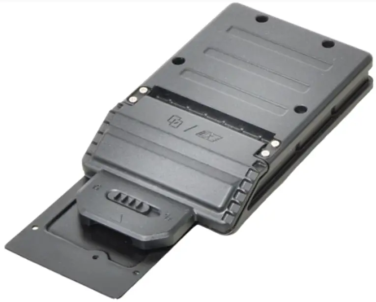
Package Contents
If any of following items is damaged, please contact your retailer.
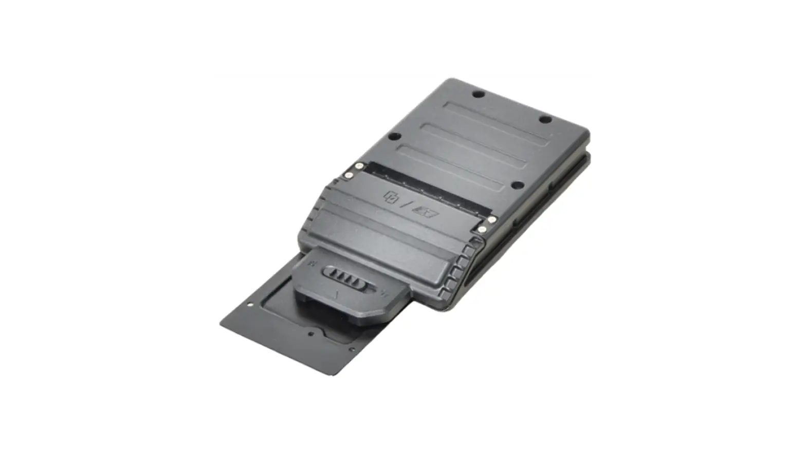
PCMCIA module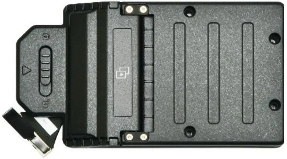
OR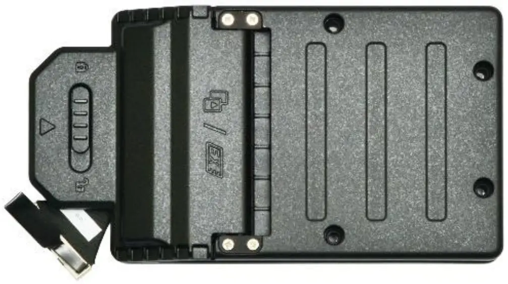
CTO door plate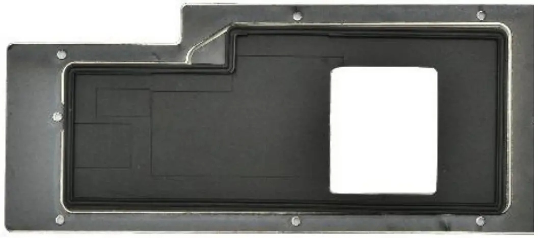
Screw & O RING
(8+6+2+8)
PCMCIA Module Screws
| Screw Name | Screw Type | Quantity |
| ISOT-M2.0X3L | 8 (CTO door plate to lower case) | |
| ISOT-M2.6X4L | 2 (module to lower case) | |
| M2.6X12L & O RING | 6 (module to lower case) |
![]() NOTE
NOTE
The pictures are for reference only, actual items may slightly differ.
Installation
This section will guide you on how to install the expansion modules to your tablet PC.![]() Note: Make sure to remove the battery before installing any type of expansion modules. For more information on how to remove/install the battery, please refer to the tablet PC service guide.
Note: Make sure to remove the battery before installing any type of expansion modules. For more information on how to remove/install the battery, please refer to the tablet PC service guide.
Installing the PCMCIA Module
To install the PCMCIA module, follow the steps below:
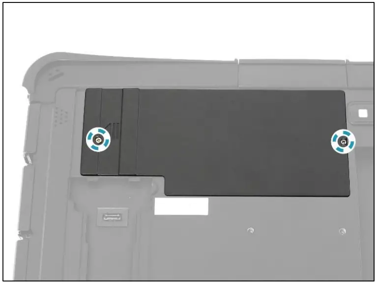
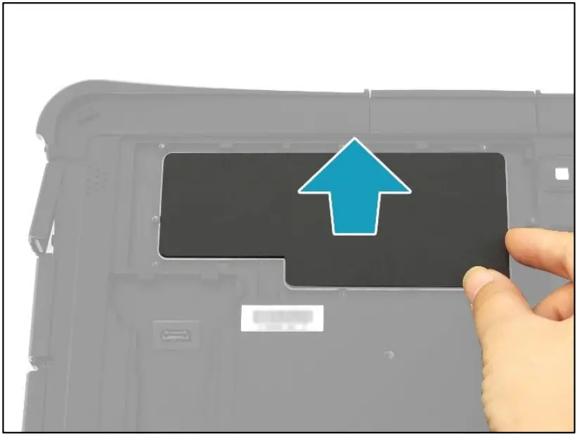
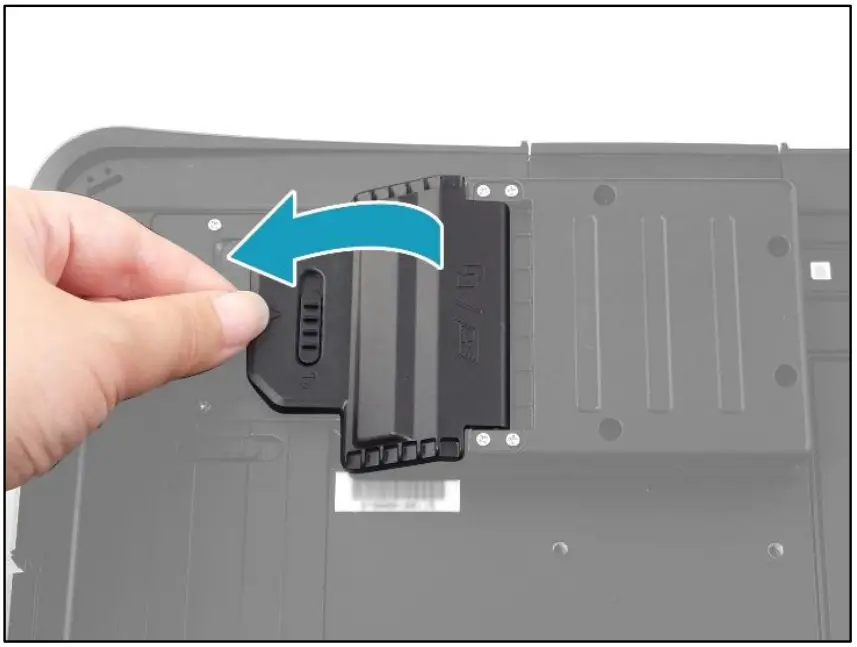
- Remove the 2 screw securing the CTO door to the lower case.

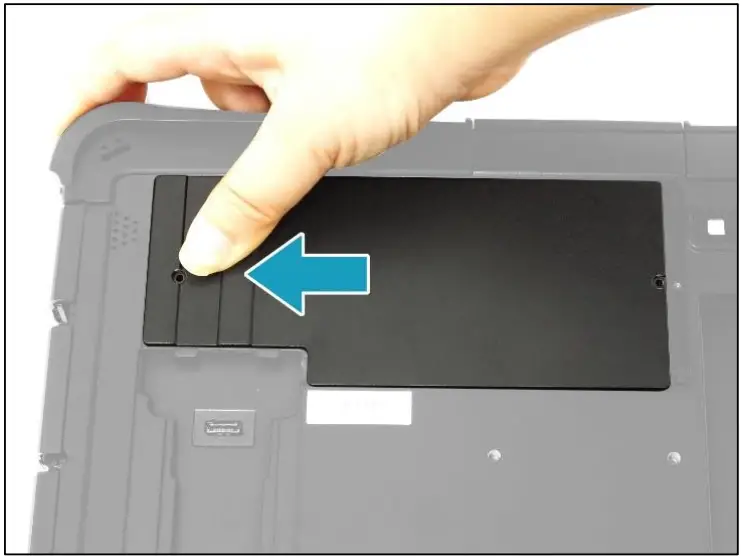
- Slide the CTO door to the left to disengage it from the tabs.

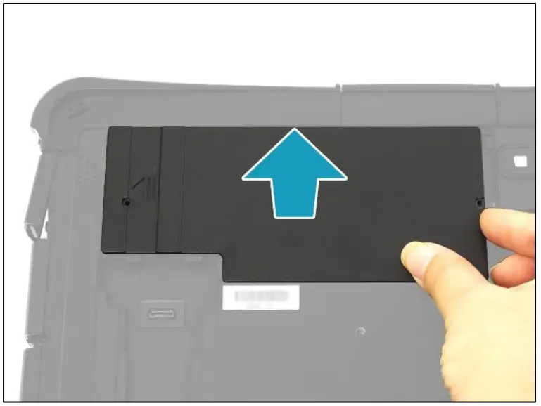
- Remove the CTO door.

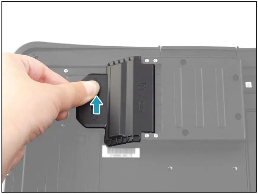
- Remove the CTO door seal out of its compartment

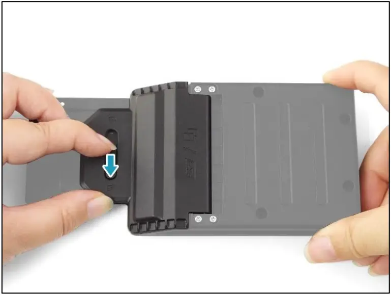
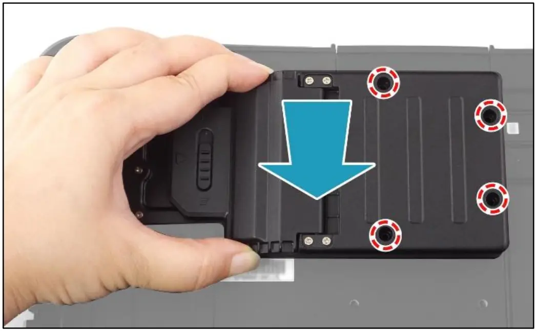
- Slide the knob to the right to unlock the CTO box door.

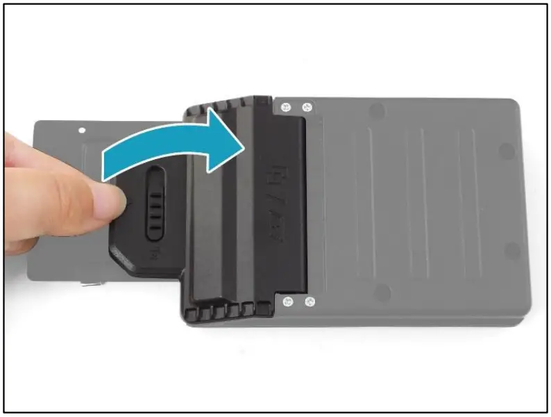
- Open the CTO box door.

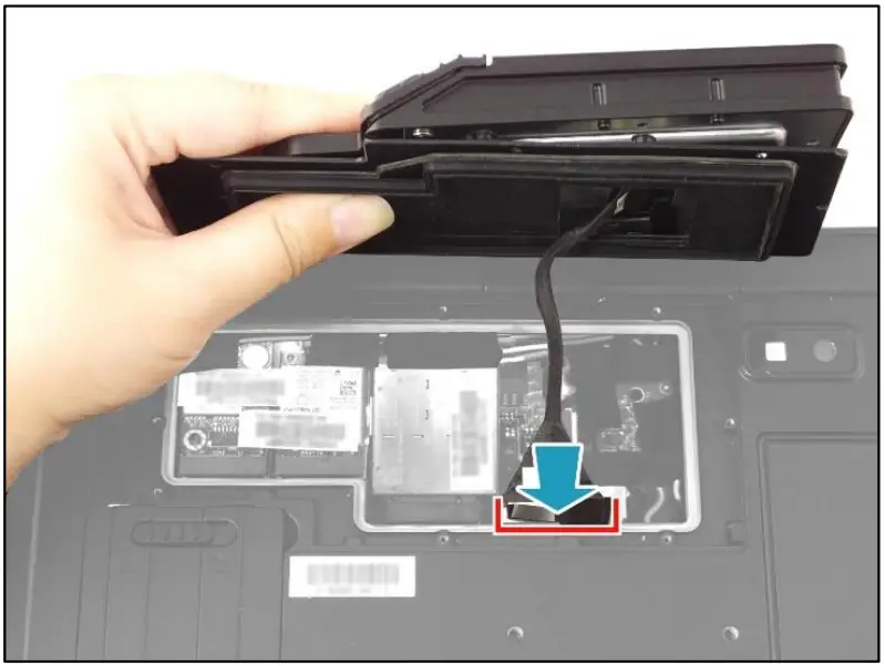
- Connect the PCMCIA module harness to the mainboard connector

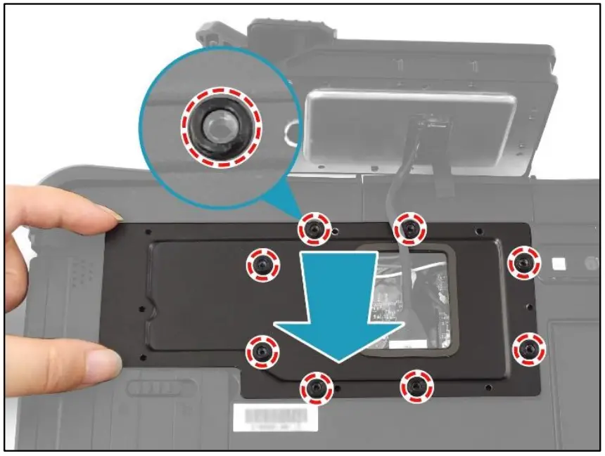
- By aligning with the screw holes, install the CTO door plate onto its compartment on the lower case. Make sure the rubber washers are properly seated into their respective screw holes

- Attach the 8 screws to secure the CTO door plate to the lower case.

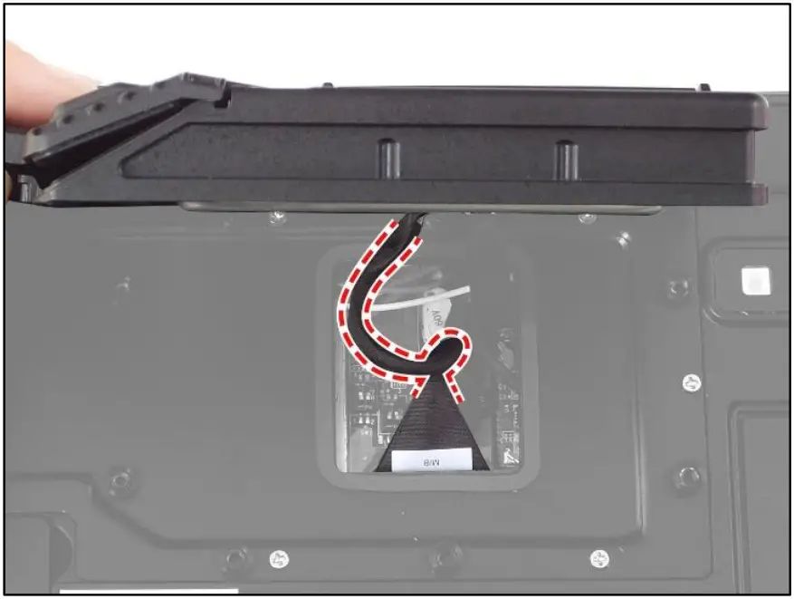
- Fold and place the excess cable of the PCMCIA module harness into the gap for proper cable routing.

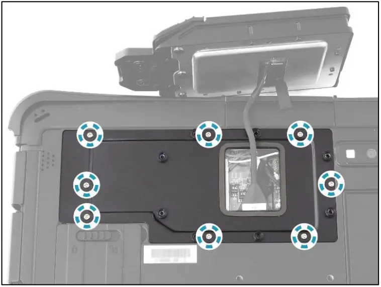
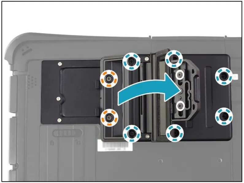
- By aligning with the screw holes, install the PCMCIA module onto its slot on the lower case

- Attach the 8 screws to secure the PCMCIA module to the lower case.
- M2.6X12L & O RING (marked with blue-white circle): 6 screws
- ISOT-M2.6X4L (marked with orange-white circle): 2 screws

- Close the CTO box door.

- Slide the knob to the left to lock the CTO box door.

PCMCIA Module Screws
| Screw Name | Screw Type | Quantity | Torque |
| ISOT-M2.0X3L | 8 (CTO door plate to lower case) | 2.0 ± 0.2 Kgf-cm | |
| ISOT-M2.6X4L |  | 2 (module to lower case) | 2.5 ± 0.2 Kgf-cm |
| M2.6X12L & O RING | 6 (module to lower case) | 2.5 ± 0.2 Kgf-cm |
Twinhead International Corp.
11F, No.550, Ruiguang Rd., Neihu, Taipei 11492, Taiwan, R.O.C.
P/N: 62+030970+00
© 2021 Twinhead International Corp and/or its affiliates. All rights reserved.
![]()


