![]()
R11 Rugged Tablet Expansion Modules
GLAN_RS232_Smart Card (3-in-1)
User Manual P/N: 62+030990+40
© 2021 Twinhead International Corp and/or its affiliates. All rights reserved.
Package Contents
If any of the following items are damaged, please contact your retailer.
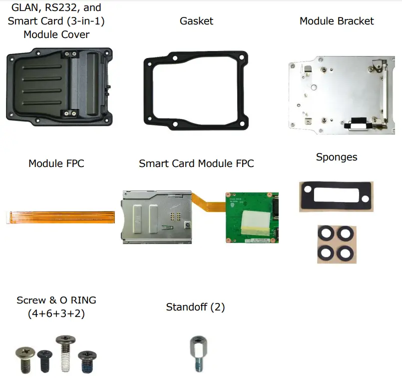
Expansion Modules GLAN_RS232_Smart Card (3-in-1)
GLAN, RS232, and Smart Card (3-in-1) Module Screws
| Screw Name | Screw Type | Quantity | Torque |
| ISOT-M2.0X4L | 2 (bracket to lower case) | 2.0 ± 0.3 Kgf-cm | |
| 4 (3-in-1 board to bracket) | |||
| ISOT-M2.0X7L | 3 (smart card reader to bracket) | 2.0 ± 0.3 Kgf-cm | |
| ISOT-M2.6X4L | 2 (cover to lower case) | 2.0 ± 0.3 Kgf-cm | |
| M2.6X6L 8c 0 RING | 4 (cover to lower case) | 2.0 ± 0.3 Kgf-cm | |
| Standoff | 2 | 3.0 ± 0.3 Kgf-cm |
NOTE
The pictures are for reference only, actual items may slightly differ.
Installation
This section will guide you on how to install the expansion modules to your tablet PC.
Note: Make sure to remove the battery before installing any type of expansion module. For more information on how to remove/install the battery, please refer to the tablet PC service guide.
Installing the GLAN, RS232, and Smart Card (3-in-1) Module
To install the GLAN, RS232, and smart card module, follow the steps below:
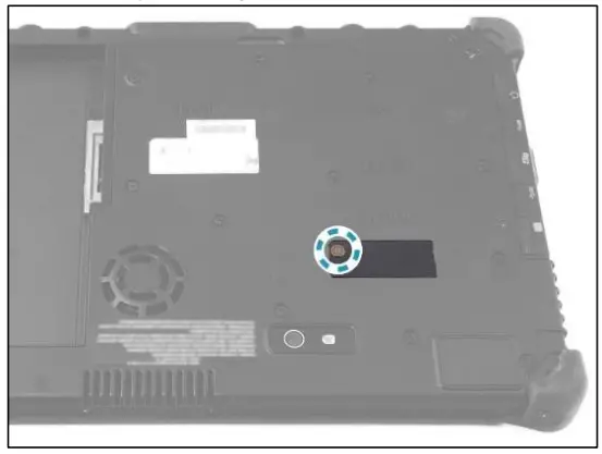
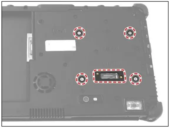
- Remove the screw securing the mylar on the DDR door.

- Remove the mylars from the DDR door.

- Attach the expansion sponge and four sponges to the DDR door.

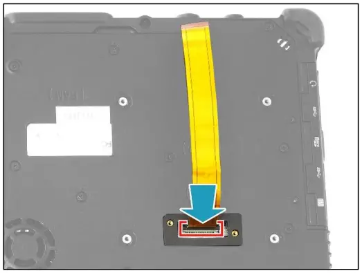
- Connect the 3-in-1 module FPC to the mainboard connector.

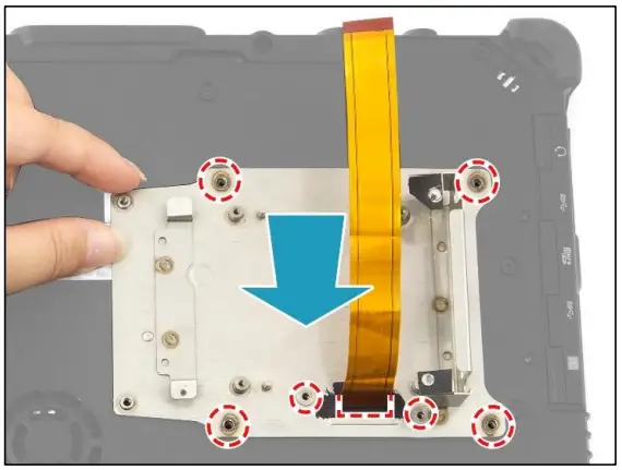
- By aligning with the screw holes, install the RJ-45 bracket onto its slot on the lower case.

- Attach the 2 screws to secure the RJ-45 bracket to the lower case.

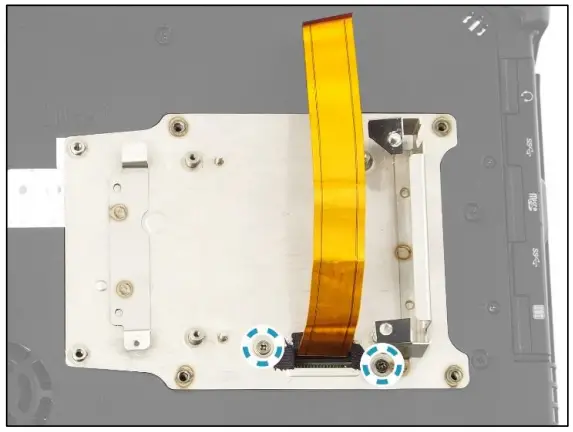
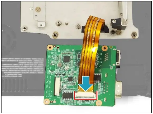
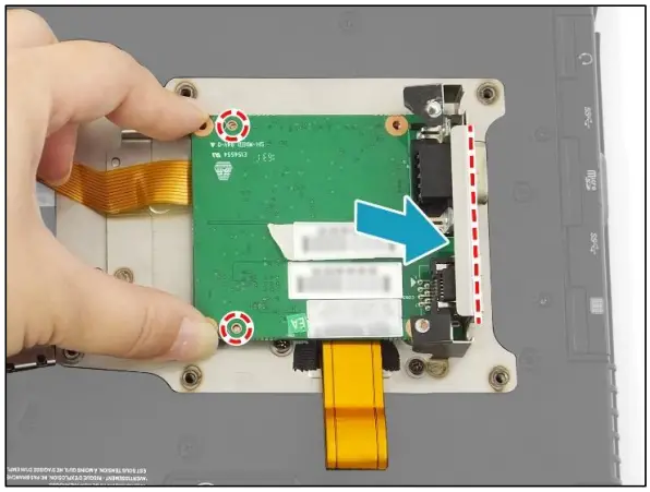
- Connect the 3-in-1 module FPC to the 3-in-1 board connector.

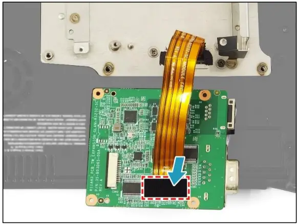
- Attach the tape to secure the 3-in-1 module FPC in place.

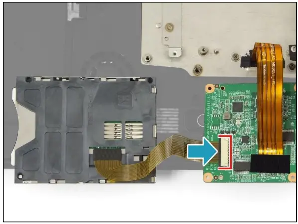
- Connect the smart card module FPC to the 3-in-1 board connector.

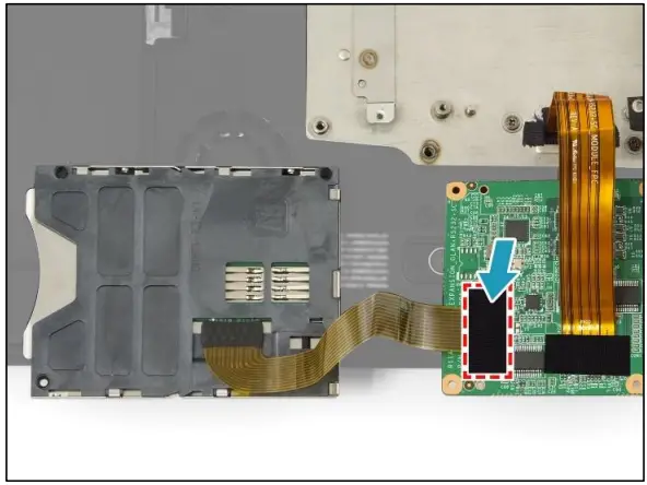
- Attach the tape to secure the smart card module FPC in place.

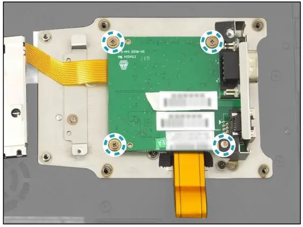
- By aligning with the guide pins and I/O port compartment, install the 3-in-1 board onto the RJ-45 bracket.

- Attach the 4 screws to secure the 3-in-1 board to the bracket.

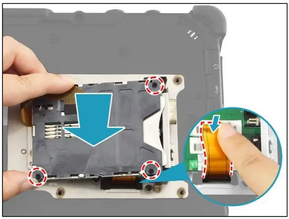
- Fold the excess of the 3-in-1 module FPC and place it onto the 3-in-1 board. Then, by aligning with the screw holes, place the smart card reader on the top of the installed 3-in-1 board.

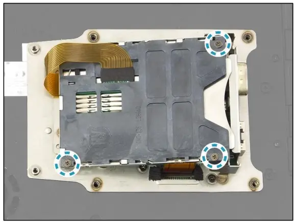
- Attach the 3 screws to secure the smart card reader in place.
- By aligning with the screw holes, place the gasket onto the RJ-45 bracket.

- By aligning with the screw holes, install the 3-in-1 module cover on the top of the installed gasket.

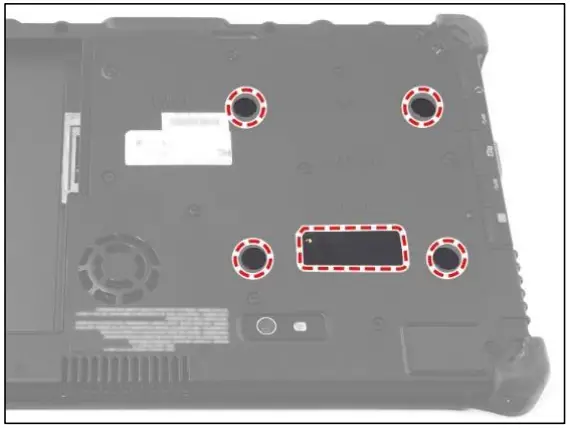
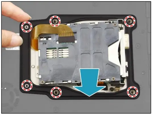
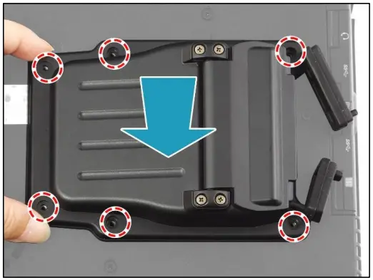
- Attach the 6 screws to secure the 3-in-1 module cover to the lower case.
➢ M2.6X6L & O RING (marked with a blue-white circle): 4 screws
➢ ISOT-M2.6X4L (marked with an orange-white circle): 2 screws
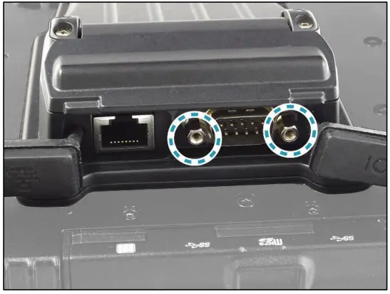
- Install the 2 standoffs to the RS232 port module.

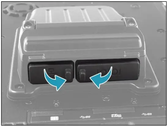
- Close the I/O port covers.

- Install the battery.

Twinhead International Corp.
11F, No.550, Ruiguang Rd., Neihu, Taipei 11492, Taiwan, R.O.C.


