ASRock IMB-1714 Jumpers and Headers
Jumpers and Headers Setting Guide
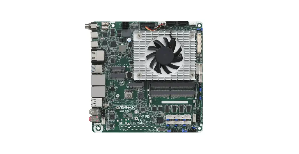
IMB-1714
IMB-X1714
The terms HDMI® and HDMI High-Definition Multimedia Interface, and the HDMI logo are trademarks or registered trademarks of HDMI Licensing LLC in the United States and other countries.
Revision History
| Date | Description |
| December 8, 2022 | First Release |
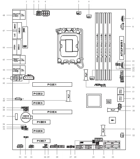
COM Port Pin9 PWR Setting Jumpers
- 1 : PWR_COM1 (For COM Port1)
PWR_COM2 (For COM Port2)
- 25 : PWR_COM3 (For COM Port3)
- PWR_COM4 (For COM Port4)
- PWR_COM5 (For COM Port5)
- PWR_COM6 (For COM Port6)
- 1- 2 : +5V
- 2- 3 : +12V
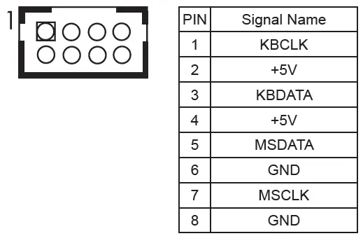
- 2: PS/2 Keyboard/Mouse Header
 LAN LED Headers
 - 3 : I225_LED3 (For LAN3 Port)

- 38 : I225_LED2 (For LAN2 Port)
I225_LED1 (For LAN1 Port)PIN Signal Name PIN Signal Name PIN Signal Name PIN Signal Name 1 LILEDP 2 LED_LNK#_ ACT 3 LED_1000# 4 LED_2500# - 4 : ATX 12V Power Connector
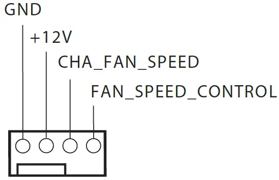
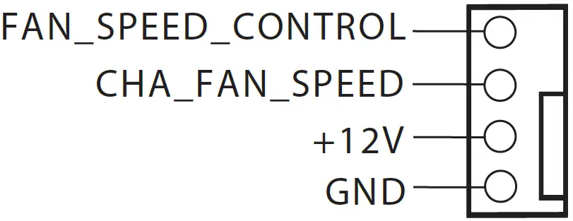
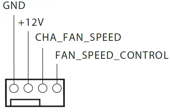
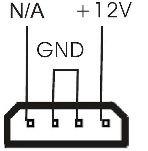
Chassis FAN Connectors (+12V)
- 5 : CHA_FAN1 GND

- 22 : CHA_FAN2

- 14 : CHA_FAN3

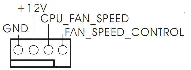
- 6 : CPU FAN Connector (+12V)

- 7 : USB 2.0 Port (USB2_13)
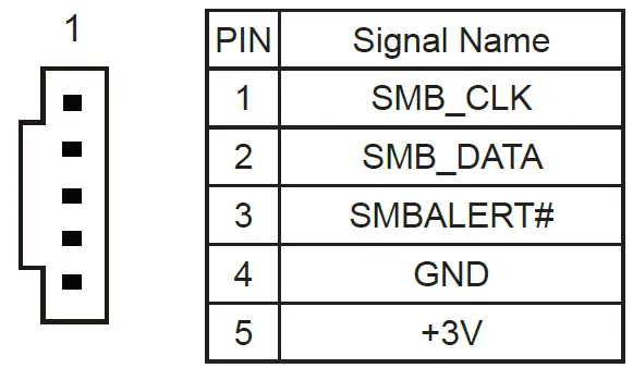
- 8 : PSU_SMB1

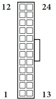
- 9 : 24-pin ATX Power Input Connector

Chassis Intrusion Headers - 10 : CI1 :
Open : Normal
Short : Active Case Open
- 13 : CI2 :
Open : Active Case
Open Short : Normal - 11 : USB 2.0 Port (USB2_12)
- 12 : PWR LOSS Jumper (PWR_LOSS1)
Open : No Power Loss
Short : Power Loss
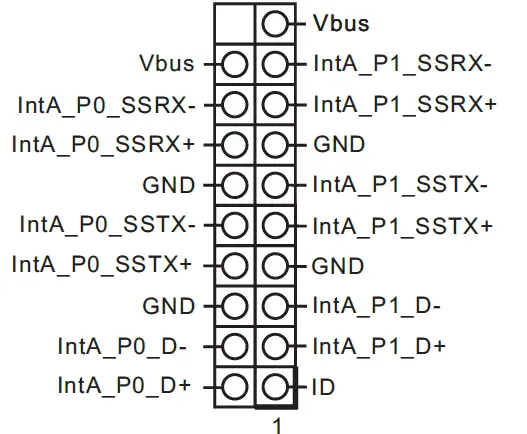
- 15 : USB 3.2 Gen1 Header (USB3_5_6)
 SATA3 Connectors
 - 17 : SATA3_4, SATA3_5 18 : SATA3_6, SATA3_7 23 : SATA3_0~3
- 19 : System Panel Header

- 24 : COM Port Headers (COM3~6) (RS232)

- 26 : ATX/AT Mode Jumper (SIO_AT1)
Open : ATX Mode
Short : AT Mode
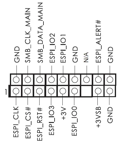
- 27 : ESPI Header

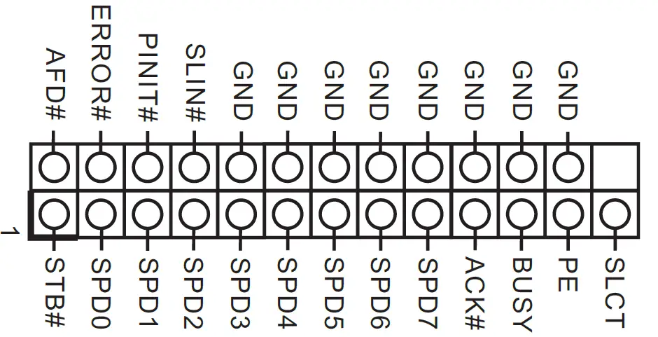
- 28 : Printer Port / GPIO Header (LPT_GPIO1)
Printer Port: GPIO:
GPIO:PIN Signal Name PIN Signal Name 26 NC 25 NA 24 GND 23 SIO_G70/GPP_E6 22 GND 21 SIO_G71/GPP_E5 20 GND 19 SIO_G72/GPP_I10 18 GND 17 SIO_GP87/GPP_H23 16 GND 15 SIO_GP86 14 GND 13 SIO_GP85 12 JGPIOPWR 11 SIO_GP84 10 JGPIOPWR 9 SIO_GP83 8 SIO_GP73 7 SIO_GP82 6 SIO_GP74 5 SIO_GP81 4 SIO_GP75 3 SIO_GP80 2 SIO_GP76 1 SIO_GP77 * If you want to use the printer port function, please short pin4 and pin5 on Digital Input / Output Power Select (JGPIO_PWR1).
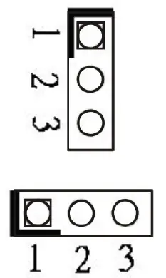
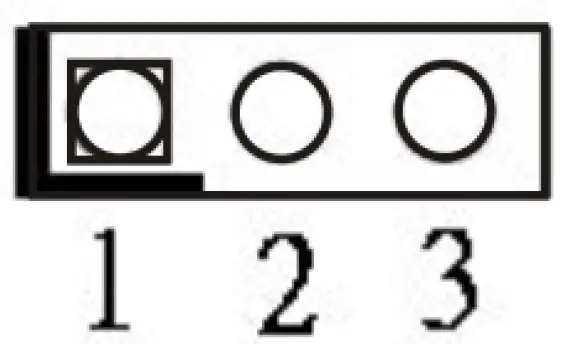
- 29 : Digital Input / Output Default Value Setting (JGPIO_SET1)
1- 2 : Pull-High
2- 3 : Pull-Low
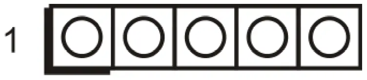
- 30 : Digital Input / Output Power Select (JGPIOPWR) (JGPIO_PWR1)
1- 2 : +12V
2- 3 : +5V
3- 4 : +5V
4- 5 : GND * If you want to use the printer port function, please short pin4 and pin5 on Digital Input / Output Power Select (JGPIO_PWR1).
 - 31 : USB 2.0 Header
(USB2_10_11)
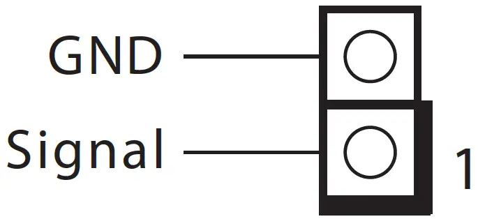
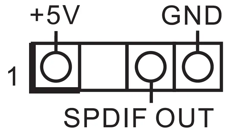
- 32 : SPDIF Header

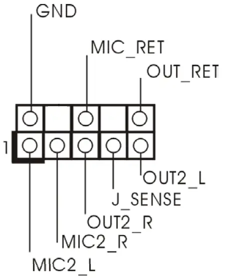
- 33 : Front Panel Audio Header

 LAN LED Headers
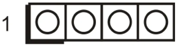

 SATA3 Connectors
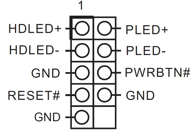


 GPIO:
GPIO: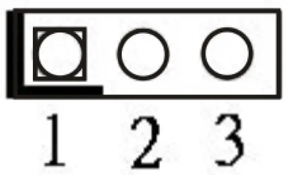
 * If you want to use the printer port function, please short pin4 and pin5 on Digital Input / Output Power Select (JGPIO_PWR1).
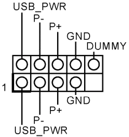

- 34 : Buzzer (BUZZ2)

- 35 : Clear CMOS Headers

CLRMOS2
Open : Normal
Short : Auto Clear CMOS (Power Off) CLRMOS1
1- 2 : Normal
2- 3 : Clear CMOS
- 36 : PWR_BAT1

- 37 : MCU_CON1
- 39 : DACC1
Open : No ACC
Short : ACC * Auto clear CMOS when system boot improperly.
 - 41 : 5-pin Thunderbolt AIC Connector (TB1)

PIN Signal Name PIN Signal Name PIN Signal Name PIN Signal Name PIN Signal Name 5 GND 4 TBT_SLP_S5_S4# 3 SLP_S3# 2 TBCIO_PLUG_EVENT_R2 1 TB_FRC_PWR - 42 : PCIe Power Connector

- 43 : Audio Jacks
Blue – Line In
Green – Line
Out Pink – Mic In - 44 : Top : RJ45 LAN Port (LAN1) (Supports POE)
Bottom : USB 3.2 Gen2 Ports (USB3_3_4) - 45 : Top : RJ45 LAN Port (LAN2) (Supports vPRO)
Middle : USB 3.2 Gen2 Port (USB3_9)
Bottom : USB 3.2 Gen2x2 Type-C Port (TC_U7_8) - 46 : Top : COM Port (COM2) (RS232/422/485)*
Bottom : D-Sub Port (VGA1) - 47 : Top : COM Port (COM1) (RS232/422/485)*
Bottom Right : DisplayPort (DP1)
Bottom Left : HDMI Port (HDMI1) - 48 : Top : RJ45 LAN Port (LAN3)
Bottom : USB 3.2 Gen2 Ports (USB3_1_2)


 * Auto clear CMOS when system boot improperly.
* This motherboard supports RS232/422/485 on COM1, 2 ports. Please refer to below table for the pin definition. In addition, COM1, 2 ports (RS232/422/485) can be adjusted in BIOS setup utility > Advanced Screen > Super IO Configuration. You may refer to our user manual for details.
COM1, 2 Port Pin Definition
| PIN | RS232 | RS422 | RS485 |
| 1 | DCD, Data Carrier Detect | TX- | RTX- |
| 2 | RXD, Receive Data | TX+ | RTX+ |
| 3 | TXD, Transmit Data | RX+ | N/A |
| 4 | DTR, Data Terminal Ready | RX- | N/A |
| 5 | GND | GND | GND |
| 6 | DSR, Data Set Ready | N/A | N/A |
| 7 | RTS, Request To Send | N/A | N/A |
| 8 | CTS, Clear To Send | N/A | N/A |
| 9 | No Power/5V/12V | N/A | N/A |
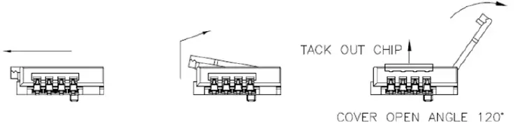
Installation of ROM Socket
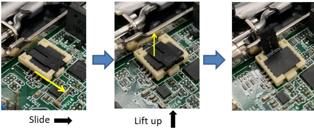
* Do not apply force to the actuator cover after ic inserted.
* Do not apply force to actuator cover when it is opening over 120 degree, Otherwise, the actuator cover may be broken.
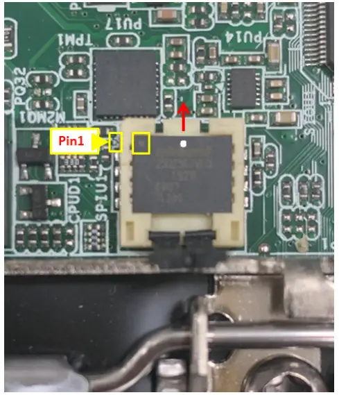
* The yellow dot (Pin1) on the ROM must be installed at pin1 position of the socket (white arrow area).
* Make sure the white dot on the ROM is installed outwards of the socket.
* For further details of how to install ROM, please refer to ASRI website.
Warning: If the installation does not follow as the picture, then it may cause severe damage to chipset & MB.
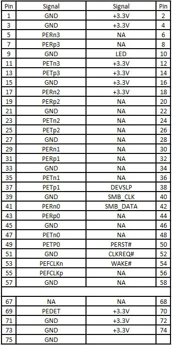
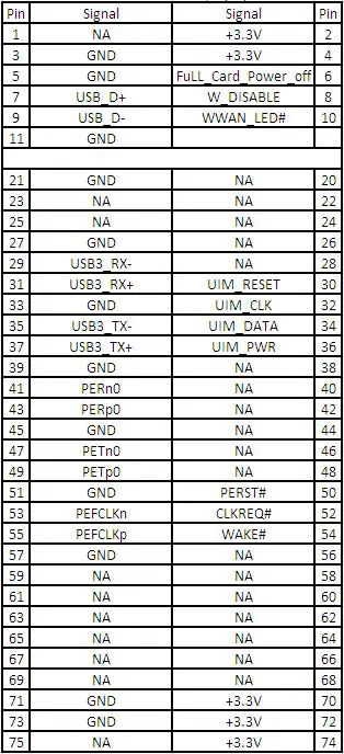
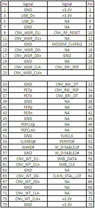
M.2 Sockets Pin Definition
- 16 : M.2 Key-M Socket (M2_M1)

- 20 : M.2 Key-B Socket (M2_B1)

- 21 : M.2 Key-M Socket (M2_M2) (For IMB-X1714 Only)
- 40 : M.2 Key-E Socket (M2_E1)