![]()
User Guide
UG000402
AS5x47U Motor Board
Motor Board User Manual
AS5047U / AS5147U
Introduction
The AS5x47U motor board is a simple PCB that is designed to adapt to standard size BLDC or stepper motors. It allows easy and quick evaluation of the AS5x47 magnetic position sensor family. The sensor and all necessary external components are already soldered to the PCB.
1.1 Kit Content
Figure 1:
AS5x47U Motor Board Kit Content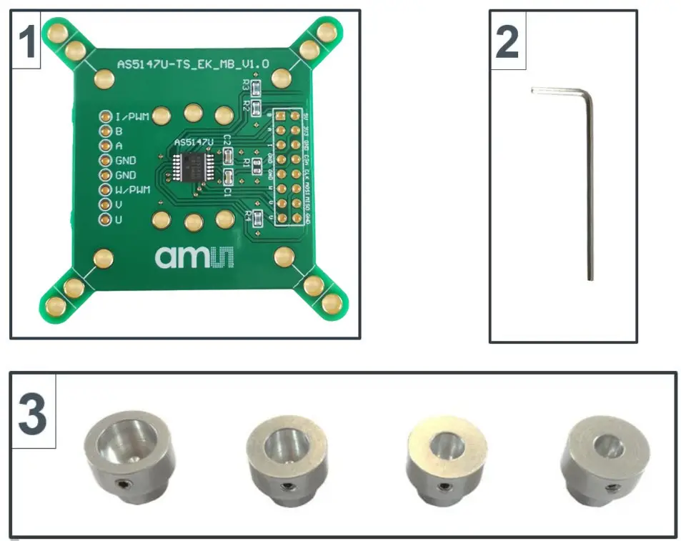
- Motor Board
- Allen Key
- Magnet Holders
1.2 Ordering Information
| # | ITEM | Description |
| 1 | AS5x47U-TS_EK_MB | Motor Board |
| 2 | Allen key | 1.5 mm |
| 3 | Magnet holders | Diameters: 10mm, 8mm, 6mm, 5mm |
Description
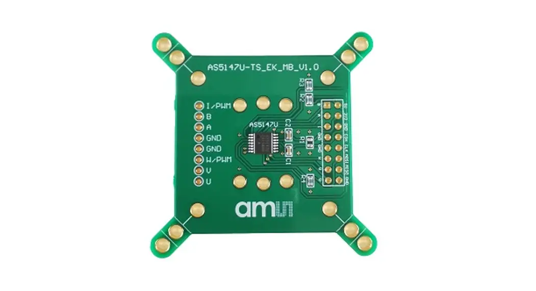
The PCB can either be connected to an external microcontroller or to the USB I&P Box which is available on our webpage. (USB I&P Box) P1 has to be populated with a 2×8 pin header and is required for power supply as well as SPI, ABI, UVW/PWM interfaces. The resistor R1 allows selecting between 5V or 3.3V operation. When R1 is shorted only 3.3V operation is possible. Furthermore, the test pins on the bottom of the PCB give easy access to incremental outputs (ABI and UVW) for probing and measuring with an oscilloscope.
Figure 2 :
Motor Board 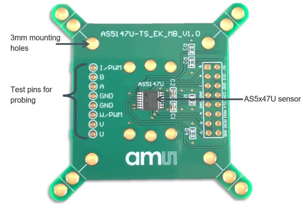
2.1 Mounting on Motor
Figure 3 :
Mounting the AS5x47U Motor Board 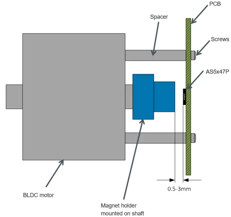
Pinout
Figure 4 :
Pinout 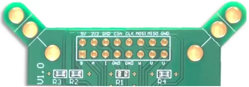
Figure 5:
Pin Description
| Pin# Board | Symbol Board | Type Description | |
| P1 – 1 | A | Digital output | Incremental signal A (quadrature) |
| P1 -2 | B | Digital output | Incremental signal B (quadrature) |
| P1 – 3 | I | Digital output | Incremental signal I (index) or PWM |
| P1 – 4 | TEST | Test pin (connect to ground) | |
| P1 – 5 | NC | Not connected | |
| P1 – 6 | U | Digital output | Commutation signal U |
| P1 – 7 | V | Digital output | Commutation signal V |
| P1 – 8 | W | Digital output | Commutation signal W or PWM |
| P1 – 9 | 5V | Power supply | Positive supply voltage |
| P1 – 10 | 3V3 | Power supply | 3.3V LDO output |
| P1 -11 | NC | Not connected | |
| P1 – 12 | CST | Digital input | SPI chip select (active low) |
| P1 -13 | CLK | Digital input | SPI Clock |
| P1 -14 | MOSI | Digital input | SPI MOSI |
| P1 -15 | MISO | Digital output | SPI MISO |
| P1 -16 | GND | Power supply | Ground |
Hardware
4.1 Schematic
Figure 6 :
AS5x47U-TS_EK_MB Schematics 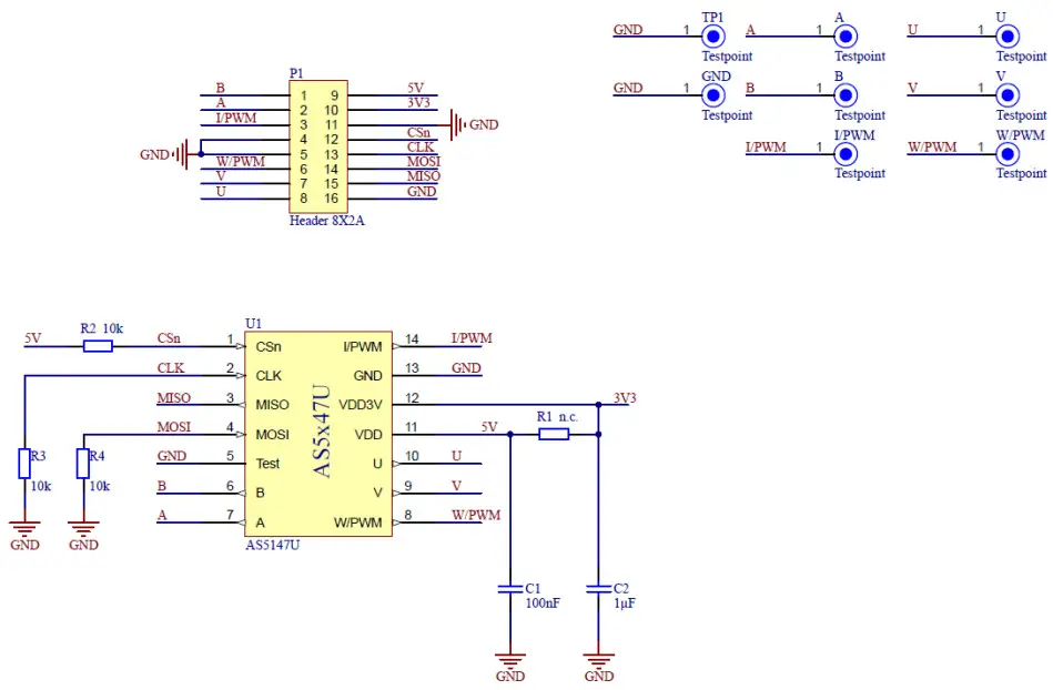
4.2 PCB Layout
Figure 7 :
AS5x47U-TS_EK_MB PCB Layout 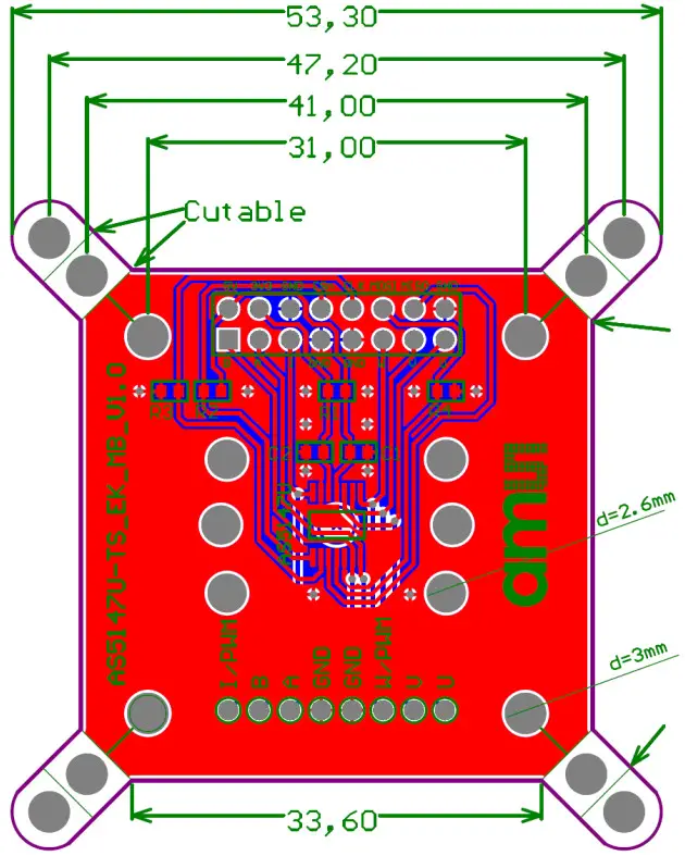
Revision Information
Initial Version
- Page and figure numbers for the previous version may differ from page and figure numbers in the current revision.
- Correction of typographical errors is not explicitly mentioned.
Legal Information
Copyrights & Disclaimer
Copyright ams AG, Tobelbader Strasse 30, 8141 Premstaetten, Austria-Europe. Trademarks Registered. All rights reserved. The material herein may not be reproduced, adapted, merged, translated, stored, or used without the prior written consent of the copyright owner. Demo Kits, Evaluation Kits, and Reference Designs are provided to the recipient on an “as is” basis for demonstration and evaluation purposes only and are not considered to be finished end-products intended and fit for general consumer use, commercial applications, and applications with special requirements such as but not limited to medical equipment or automotive applications. Demo Kits, Evaluation Kits, and Reference Designs have not been tested for compliance with electromagnetic compatibility (EMC) standards and directives unless otherwise specified. Demo Kits, Evaluation Kits, and Reference Designs shall be used by qualified personnel only. AMS AG reserves the right to change the functionality and price of Demo Kits, Evaluation Kits, and Reference Designs at any time and without notice. Any express or implied warranties, including, but not limited to the implied warranties of merchantability and fitness for a particular purpose are disclaimed. Any claims and demands and any direct, indirect, incidental, special, exemplary, or consequential damages arising from the inadequacy of the provided Demo Kits, Evaluation Kits, and Reference Designs or incurred losses of any kind (e.g. loss of use, data, or profits or business interruption however caused) as a consequence of their use are excluded. AMS AG shall not be liable to the recipient or any third party for any damages, including but not limited to personal injury, property damage, loss of profits, loss of use, interruption of business or indirect, special, incidental or consequential damages, of any kind, in connection with or arising out of the furnishing, performance or use of the technical data herein. No obligation or liability to recipient or any third party shall arise or flow out of ams AG rendering of technical or other services.
RoHS Compliant & ams Green Statement
RoHS Compliant: The term RoHS compliant means that as AG products fully comply with current RoHS directives. Our semiconductor products do not contain any chemicals for all 6 substance categories plus additional 4 substance categories (per amendment EU 2015/863), including the requirement that lead not exceed 0.1% by weight in homogeneous materials. Where designed to be soldered at high temperatures, RoHS compliant products are suitable for use in specified lead-free processes. AMS Green (RoHS compliant and no Sb/Br/Cl): ams Green defines that in addition to RoHS compliance, our products are free of Bromine (Br) and Antimony (Sb) based flame retardants (Br or Sb do not exceed 0.1% by weight in homogeneous material) and do not contain Chlorine (Cl does not exceed 0.1% by weight in homogeneous material). Important Information: The information provided in this statement represents ams AG’s knowledge and belief as of the date that it is provided. AMS AG bases its knowledge and belief on information provided by third parties and makes no representation or warranty as to the accuracy of such information. Efforts are underway to better integrate information from third parties. AMS AG has taken and continues to take reasonable steps to provide representative and accurate information but may not have conducted destructive testing or chemical analysis on incoming materials and chemicals. AMS AG and ams AG suppliers consider certain information to be proprietary, and thus CAS numbers and other limited information may not be available for release.
| Headquarters | Please visit our website at www.ams.com |
| AMS AG | Buy our products or get free samples online at www.ams.com/Products |
| Tobelbader Strasse 30 | Technical Support is available at www.ams.com/Technical-Support |
| 8141 Premstaetten | Provide feedback about this document at www.ams.com/Document-Feedback |
| Austria, Europe | For sales offices, distributors and representatives go to www.ams.com/Contact |
| Tel: +43 (0) 3136 500 0 | For further information and requests, e-mail us at [email protected] |
Demo Kit Manual • PUBLIC
UG000402 • v1-00 • 2021-Oct-01


