ams AS5048 Adapter Board
AS5048 Adapter Board User Manual
Product Information
The AS5048 adapter board is a small PCB designed for easy and quick testing or evaluation of the AS5048 magnetic position sensor.
It eliminates the need to build a test fixture or design your own PCB. The board can be connected to an external microcontroller or to the Universal Connector Board (AS5xxx-UCB) in combination with a NI USB-8451 box and a provided LabVIEW software. The PCB is available in two versions, one populated with an AS5048A with SPI interface or an AS5048B with I2C interface.
Kit Content
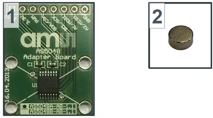
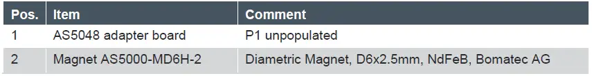
The kit includes an AS5048 adapter board and a diametric magnet (D6x2.5mm, NdFeB, Bomatec AG). P1 on the board needs to be populated with a 1×8 pin header and is required for power supply as well as SPI/I2C and PWM interfaces.
Board Description
The AS5048 adapter board has a compact design and is equipped with an AS5048 magnetic position sensor. The board can be easily mounted on an external microcontroller or on the Universal Connector Board (AS5xxx-UCB) in combination with a NI USB-8451 box and a provided LabVIEW software. The board is available in two versions, one populated with an AS5048A with SPI interface or an AS5048B with I2C interface.
Product Usage Instructions
Mounting the AS5048 Adapter Board
To mount the AS5048 adapter board, follow these steps:
- Populate P1 on the board with a 1×8 pin header.
- Connect the board to an external microcontroller or to the Universal Connector Board (AS5xxx-UCB) in combination with a NI USB-8451 box and a provided LabVIEW software.
Operation Cases
The AS5048 adapter board supports multi-device SPI daisy chain mode. Refer to section 4 of the user manual for more information.
Software Example Source Code
Refer to section 5 of the user manual for software example source code.
AS5048-EK-AB Hardware
Refer to sections 6.1 and 6.2 of the user manual for AS5048-EK-AB schematics and PCB layout, respectively.
Ordering and Contact Information
Refer to section 7 of the user manual for ordering and contact information.
Copyrights and Disclaimer
Refer to section 8 of the user manual for copyrights and disclaimer information.
Revision History
| Revision | Date | Owner | Description |
| 1.0 | 01.10.2009 | Initial version | |
| 1.1 | 18.10.2013 | azen | Updated to new template |
| 1.2 | 14.01.2013 | rph | Minor corrections in section 4.1 |
| 1.3 | 01.07.2014 | mzie | Updated ordering code, added section 1.1, updated figure 2-9,updated source code |
Introduction
The AS5048 adapter board is a small PCB allowing simple and quick testing or evaluation of the AS5048 magnetic position sensor without the need to build a test fixture or design an own PCB.
Kit Content
Figure 1: Kit Content
Board Description
The PCB can either be connected to an external microcontroller or to the Universal Connector Board (AS5xxx-UCB) in combination with a NI USB-8451 box and a provided LabVIEW software.
P1 has to be populated with a 1×8 pin header and is required for power supply as well as SPI/I2C and PWM interfaces.
The PCB is available in two versions. Either populated with an AS5048A with SPI or AS5048B with I2C interface.
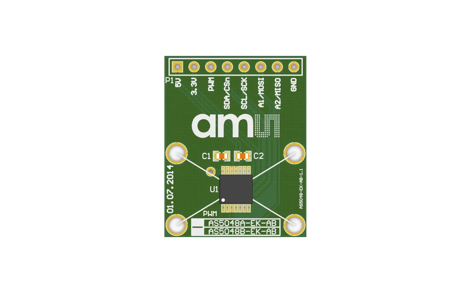
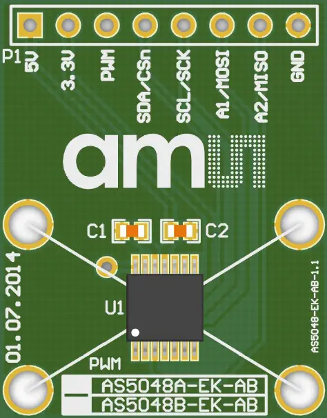
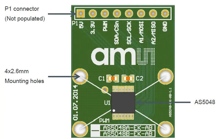
Figure 2: AS5048 adapter board
Mounting the AS5048 adapter board
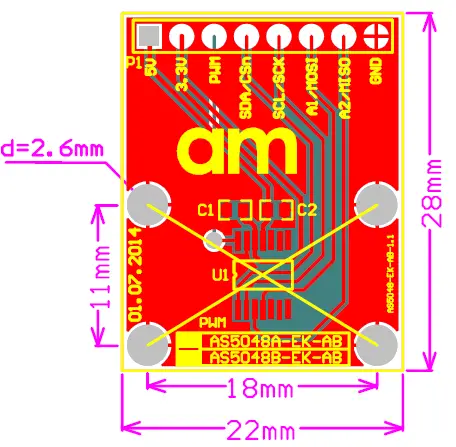
Figure 3: Mounting and dimensions
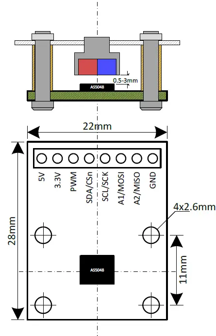
A 6×2.5mm diametric magnet must be placed over or under the AS5048 sensor, and should be centered on the middle of the package with a tolerance of 0.5mm. The airgap between the magnet surface and the package should be maintained in the range 0.5mm to 3mm. The magnet holder must not be ferromagnetic. Materials as brass, copper, aluminum, stainless steel are the best choices to make this part.
AS5048 adapter board and pinout
Figure 4: AS5048 adapter board connectors and encoder pinout
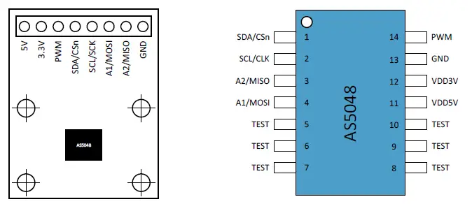
| Pin# Board | Pin# AS5048 | Symbol Board | Description |
| P1 – 1 | 11 | 5V | Supply voltage |
| P1 – 2 | 12 | 3.3V | 3V-Regulator output; internally regulated from VDD. Connect to VDD for 3V supply voltage |
| P1 – 3 | 14 | PWM | Pulse width modulation output |
| P1 – 4 | 1 | SDA/CSn | SPI chip select-active low; shared with I2C data pin |
| P1 – 5 | 2 | SCL/SCK | SPI clock input; shared with I2C clock input |
| P1 – 6 | 4 | A1/MOSI | SPI master out/slave in; shared with I2C address selection pin 1 |
| P1 – 7 | 3 | A2/MISO | SPI master in/slave out; shared with I2C address selection pin 2 |
| P1 – 8 | 13 | GND | Supply ground |
Operation cases
The most complete and accurate solution for a MCU to read the angle of a magnet is the SPI interface.
One Device SPI mode, unidirectional – 3 wire
The AS5048-EK-AB can be directly connected to an industry standard SPI port of a microcontroller.
The minimum connection requirement for unidirectional communication (angle + alarm values reading) between the microcontroller and the AS5048 are MISO, SCK, SS/.
The angle will be read at each 16-bit SPI transfer. See AS5048 datasheet register table, register 3FFFh.
Figure 5: Using the SPI Interface unidirectional with a microcontroller
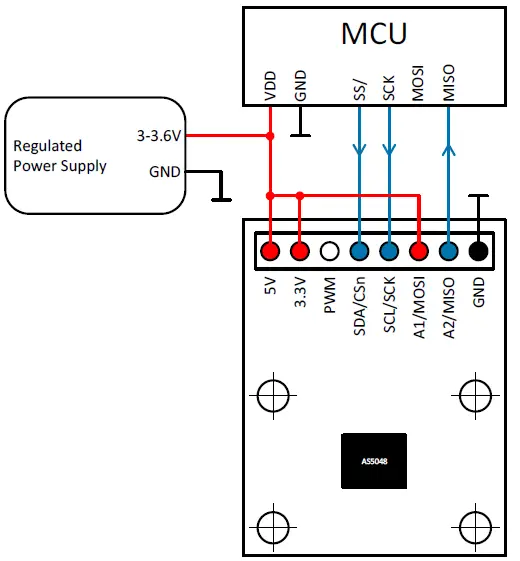
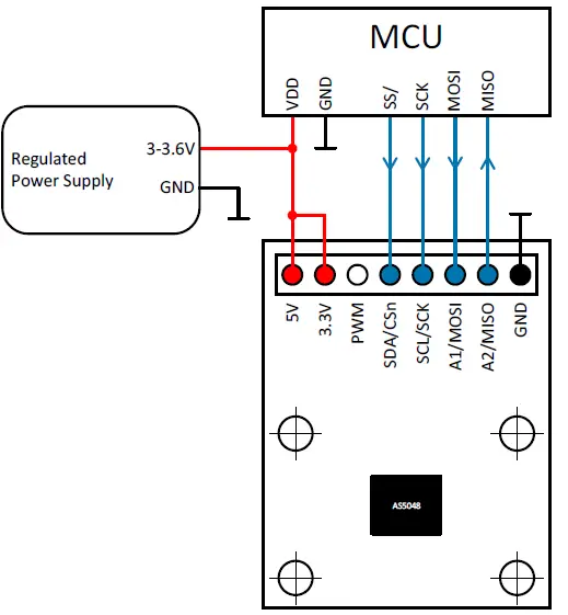
One device SPI mode, bidirectional – 4 wire
If other registers than only angle values have to be read, or in order to write registers into the AS5048, the signal MOSI is necessary.
Figure 6: Using the SPI Interface biidirectional with a microcontroller
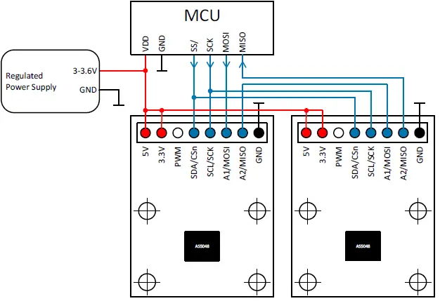
Multi devices SPI Daisy chain mode
The AS5048 can be daisy chained, using 4 wires only for SPI communication.
In this configuration with n x encoders, the sequence will be processed as follow:
- MCU sets SS/ = 0
- MCU shifts n x 16-bit (e.g. READ command FFFFh) through the chain
- MCU sets SS/=1
At that point all the n x encoders have received the READ command FFFFh. - MCU sets SS/=0
- MCU shifts n x 16-bit (e.g. NOP command 0000h)
- MCU sets SS/=1
At that point the n x 16-bit received on MISO are the n x angle values.
Figure 7: Multi Devices in Daisy chain mode
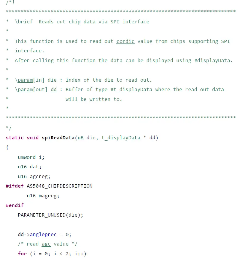
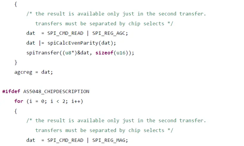
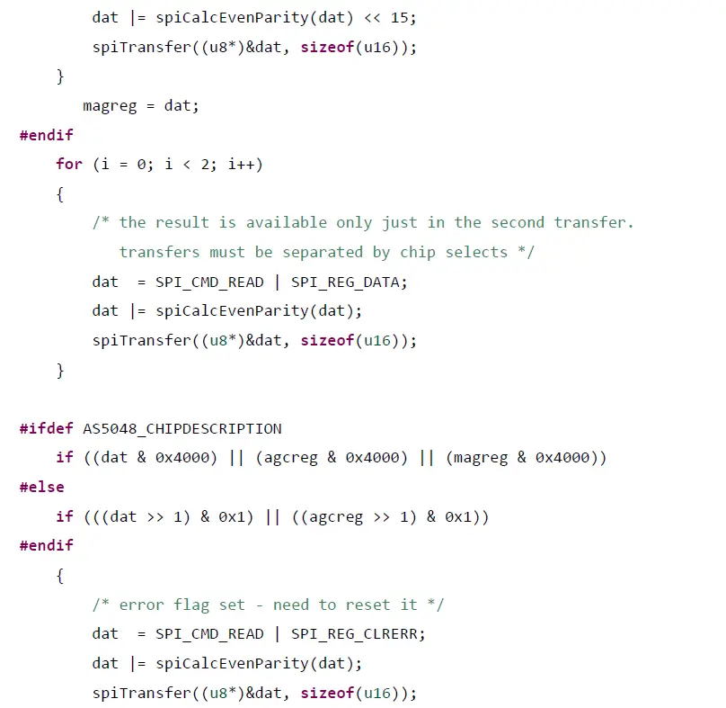
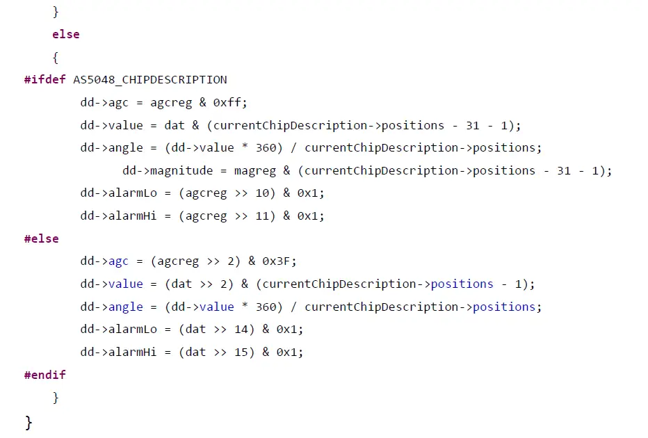
Software example source code
The following source code shows a 4-wire SPI application case
AS5048-EK-AB Hardware
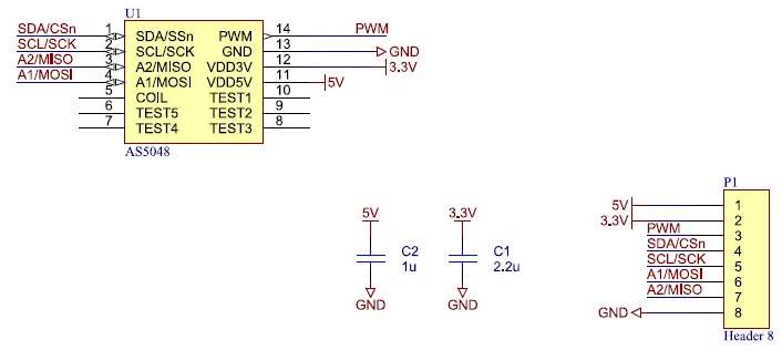
AS5048-EK-AB schematics
Figure 8: AS5048-EK-AB schematics
AS5048-EK-AB PCB layout
Figure 9: AS5048-EK-AB PCB layout
Ordering & Contact Information

Buy our products or get free samples online at: www.ams.com/ICdirect
Technical Support is available at: www.ams.com/Technical-Support
Provide feedback about this document at: www.ams.com/Document-Feedback
For further information and requests, e-mail us at: [email protected]
For sales offices, distributors and representatives, please visit:
www.ams.com/contact
Headquarters ams AG
Tobelbaderstrasse 30
8141 Unterpremstaetten
Austria, Europe
Tel: +43 (0) 3136 500 0
Website: www.ams.com
Copyrights & Disclaimer
Copyright ams AG, Tobelbader Strasse 30, 8141 Unterpremstaetten, Austria-Europe. Trademarks Registered. All rights reserved. The material herein may not be reproduced, adapted, merged,translated, stored, or used without the prior written consent of the copyright owner.
Demo Kits, Evaluation Kits and Reference Designs are provided to recipient on an “as is” basis for demonstration and evaluation purposes only and are not considered to be finished end-products intended and fit for general consumer use, commercial applications and applications with special requirements such as but not limited to medical equipment or automotive applications. Demo Kits,
Evaluation Kits and Reference Designs have not been tested for compliance with electromagnetic compatibility (EMC) standards and directives, unless otherwise specified. Demo Kits, Evaluation Kits and Reference Designs shall be used by qualified personnel only.
ams AG reserves the right to change functionality and price of Demo Kits, Evaluation Kits and Reference Designs at any time and without notice.
Any express or implied warranties, including, but not limited to the implied warranties of merchantability and fitness for a particular purpose are disclaimed. Any claims and demands and any direct, indirect, incidental, special, exemplary or consequential damages arising from the inadequacy of the provided Demo Kits, Evaluation Kits and Reference Designs or incurred losses of any kind (e.g. loss of use, data or profits or business interruption however caused) as a consequence of their use are excluded.
ams AG shall not be liable to recipient or any third party for any damages, including but not limited to personal injury, property damage, loss of profits, loss of use, interruption of business or indirect,special, incidental or consequential damages, of any kind, in connection with or arising out of the furnishing, performance or use of the technical data herein. No obligation or liability to recipient or any third party shall arise or flow out of ams AG rendering of technical or other services.


