ASRock 4X4-7735U-D5 Motherboard User Manual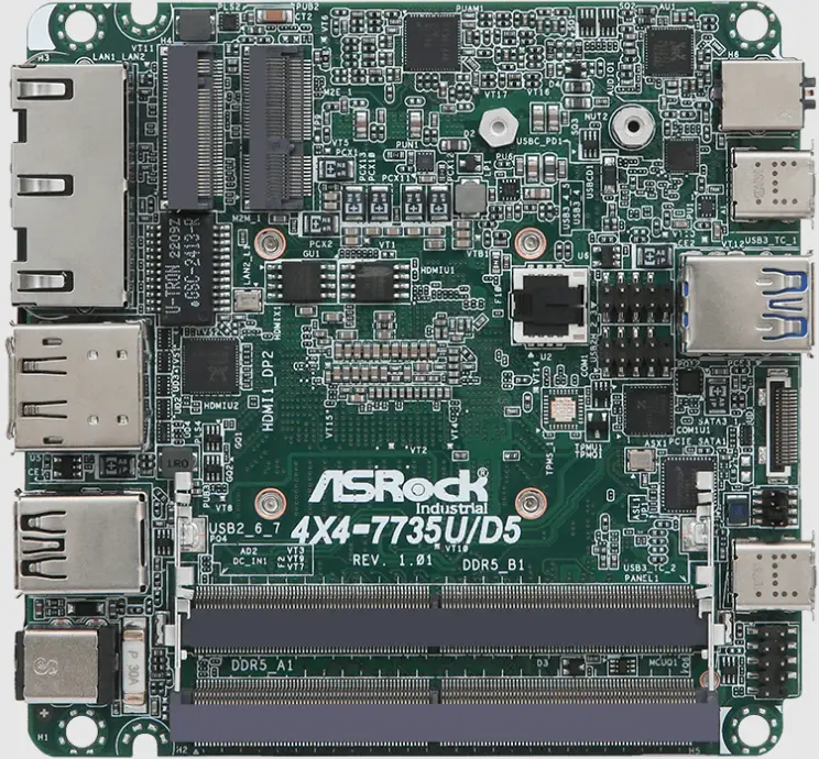
Version 1.0 Published March, 2023 Copyright©2023 AS Rockind INC. All rights reserved.
Copyright Notice:
No part of this documentation may be reproduced, transcribed, transmitted, or translated in any language, in any form or by any means, except duplication of documentation by the purchaser for backup purpose, without written consent of AS Rockind Inc.
Products and corporate names appearing in this documentation may or may not be registered trademarks or copyrights of their respective companies, and are used only for identification or explanation and to the owners’ benefit, without intent to infringe.
Disclaimer:
Specifications and information contained in this documentation are furnished for informational use only and subject to change without notice, and should not be constructed as a commitment by AS Rockind. AS Rockind assumes no responsibility for any errors or omissions that may appear in this documentation.
With respect to the contents of this documentation, AS Rockind does not provide warranty of any kind, either expressed or implied, including but not limited to the implied warranties or conditions of merchantability or fitness for a particular purpose.
In no event shall ASRockind, its directors, officers, employees, or agents be liable for any indirect, special, incidental, or consequential damages (including damages for loss of profits, loss of business, loss of data, interruption of business and the like), even if ASRockind has been advised of the possibility of such damages arising from any defect or error in the documentation or product.

This device complies with Part 15 of the FCC Rules. Operation is subject to the following two conditions:
- this device may not cause harmful interference, and
- this device must accept any interference received, including interference that may cause undesired operation.
CALIFORNIA, USA ONLY
The Lithium battery adopted on this motherboard contains Perchlorate, a toxic substance controlled in Perchlorate Best Management Practices (BMP) regulations passed by the California Legislature. When you discard the Lithium battery in California, USA, please follow the related regulations in advance. “Perchlorate Material-special handling may apply, see www.dtsc.ca.gov/hazardouswaste/ perchlorate”
ASRockind Website: http://www.asrockind.com
![]()
The terms HDMI® and HDMI High-Definition Multimedia Interface, and the HDMI logo are trademarks or registered trademarks of HDMI Licensing LLC in the United States and other countries.
CAUTION:
RISK OF EXPLOSION IF BATTERY IS REPLACED BY AN INCORRECT TYPE. DISPOSE OF USED BATTERIES ACCORDING TO THE INSTRUCTIONS.
Introduction
Thank you for purchasing AS Rockind 4X4-7735U/D5 / 4X4-7535U/D5 motherboard, a reliable motherboard produced under AS Rockind’s consistently stringent quality control. It delivers excellent performance with robust design conforming to AS Rockind’s commitment to quality and endurance. In this manual, chapter 1 and 2 contain introduction of the motherboard and stepby-step guide to the hardware installation. Chapter 3 and 4 contain the configuration guide to BIOS setup and information of the Support CD.

Because the motherboard specifications and the BIOS software might be updated, the content of this manual will be subject to change without notice. In case any modifications of this manual occur, the updated version will be available on ASRockind website without further notice. You may find the latest CPU support lists on ASRockind website as well. ASRockind website https://www.asrockind.com/ If you require technical support related to this motherboard, please visit
our website for specific information about the model you are using.
https://www.asrockind.com/support/index.asp
Package Contents
ASRockind 4X4-7735U/D5 / 4X4-7535U/D5 Motherboard (NUC 4.09” x 4.02” (104 x 102mm))
Specifications
| FormFactor | Dimensions | 4X4 (4.09-in x 4.02-in x 1.4-in, 10.4 cm x 10.2 cm x3.6 cm) |
| Processor System | CPU | AMD Ryzen™ 7 7735U (Max Speed up to 4.75GHz)AMD Ryzen™ 7 7535U (Max Speed up to4.55GHz) |
| Chipset | SoC | |
| BIOS | AMI SPI 256 Mbit | |
| ExpansionSlot | M.2 | 1 x M.2 (Key E, 2230) with PCIe x1, USB 2.0 forWireless |
| Memory | Technology | Dual Channel DDR5 4800 MHz |
| Capacity | 64GB (32 GB per DIMM) | |
| Socket | 2 x 262-pin SO-DIMM | |
| Graphics | Controller | AMD Radeon™ Graphics |
| HDMI | HDMI 2.1Max resolution up to 7680 x 4320@60Hz | |
| DisplayPort | DisplayPort 1.4a, DP++Max resolution up to 4096×2160@60Hz | |
| Multi Display | Max 4 display (included 2 outputs from Type C) | |
| Audio | Interface | Realtek ALC233, High Definition Audio |
| Ethernet | Controller/ Speed | LAN1: Realtek RTL8125BG with 10/100/1000/2500 MbpsLAN2: Realtek RTL8111EPV with 10/100/1000Mbps, support DASH function |
| Connector | 2 x RJ-45 | |
| Front I/O | USB | 2 x USB 3.2 Gen2 (Type A)2 x USB4 (5V/3A, supports DP1.4a display output) |
| Audio | 1 (headphone & microphone jack) | |
| Rear I/O | HDMI | 1 x HDMI 2.1 |
| DisplayPort | 1 x DP1.4a | |
| Ethernet | 1 x 1 Gigabit LAN, 1 x 2.5 Gigabit LAN | |
| USB | 2 x USB 2.0 | |
| DC Jack | 1 | |
| Internal Connector | USB | 2 x USB2.0 (1 x 2.00mm pitch header) |
| COM | 1 x COM (RS-232/422/485) | |
| TPM | TPM 2.0 onboard IC | |
| Storage | M.2 | 1 x M.2 (KEY M, 2242/2260/2280) with PCIe Gen4 x 4 for SSD *M.2 Key M 2280 (supported by bracket) |
| SATA | 1 x SATA3.0 (6.0 Gb/s) | |
| Watchdog Timer | Output | From Super I/O to drag RESETCON# |
| Interval | 256 segments, 0,1,2, …255sec | |
| Input PWR | 12V~19V DC-In Jack | |
| Power Requirements | Power On | AT/ATX Supported – AT : Directly PWR on as power input ready – ATX : Press button to PWR on after po wer input ready |
| Environment | Operating Temp | 0ºC ~ 60ºC |
| Storage Temp | -40ºC ~ 85°C | |
| Operating Humidity | 5% ~ 90% | |
| Storage Humidity | 5% ~ 90% |
Motherboard Layout
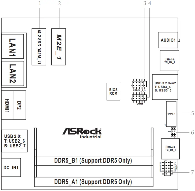
- M.2 Key-M Socket (M2M_1)
- M.2 Key-E Socket (M2E_1)
- USB 2.0 Connector (USB2H_2_3)
- COM Port Header (RS232/422/485)
- SATA3 Port (SATA3_1)
- JP1
- System Panel Header (PANEL1)
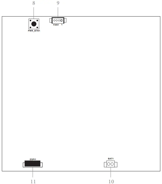
Back Side: - Power Button (PWR_BTN1)
- Fan Connector (FAN1)
- Battery Connector (BAT1)
- ESPI Connector (ESPI1)
I/O Panel
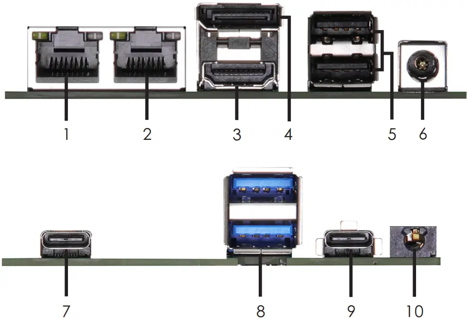
- LAN RJ-45 Port (LAN1)*
- LAN RJ-45 Port (LAN2)**
- HDMI Port (HDMI)
- DisplayPort (DP2)
- USB 2.0 Ports (USB2_6_7)
- DC-In Jack (DC_IN1)
- USB 4.0 Type-C Port (TC_U4_2)
- USB 3.2 Gen2 Ports (USB3_4_5)
- SB 4.0 Type-C Port (TC_U4_1)
- Audio Jack (AUDIO1)
There are two LEDs next to the LAN1 port. Please refer to the table below for the LAN1 port LED indications.
LAN Port LED Indications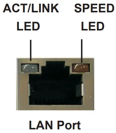
Activity/Link LED
| Status | Description |
| Off | No Link |
| Blinking | Data Activity |
| On | Link |
SPEED LED
| Status | Description |
| Off | 10Mbps connection |
| Orange | 100Mbps/1Gbps connection |
| Green | 2.5Gbps connection |
There are two LEDs next to the LAN2 port. Please refer to the table below for the LAN2 port LED indications.
LAN Port LED Indications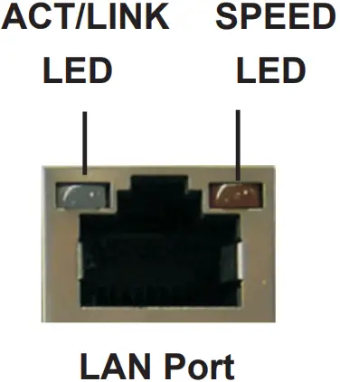
Activity/Link LED
| Status | Description |
| Off | No Link |
| Blinking | Data Activity |
| On | Link |
SPEED LED
| Status | Description |
| Off | 10Mbps connection |
| Orange | 100Mbps/1Gbps connection |
| Green | 1Gbps connection |
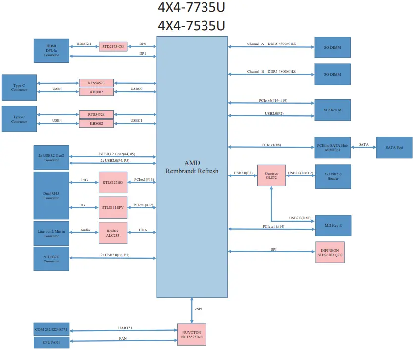
Block Diagram
Installation
Before you install the motherboard, study the configuration of your chassis to ensure that the motherboard fits into it.
Make sure to unplug the power cord before installing or removing the motherboard. Failure to do so may cause physical injuries to you and damages to motherboard components.
Screw Holes
Place screws into the holes to secure the motherboard to the chassis.
Do not over-tighten the screws! Doing so may damage the motherboard.
Pre-installation Precautions
Take note of the following precautions before you install motherboard components or change any motherboard settings.
- Unplug the power cord from the wall socket before touching any component.
- To avoid damaging the motherboard components due to static electricity,
NEVER place your motherboard directly on the carpet or the like. Also remember to use a grounded wrist strap or touch a safety grounded object before you handle components. - Hold components by the edges and do not touch the ICs.
- Whenever you uninstall any component, place it on a grounded antistatic pad or in the bag that comes with the component.
Before you install or remove any component, ensure that the power is switched off or the power cord is detached from the power supply. Failure to do so may cause severe damage to the motherboard, peripherals, and/or components.
Installation of Memory Modules (SO-DIMM)
This motherboard provides two 262-pin DDR5 (Double Data Rate 5) SO-DIMM slots.
Step 1. Align a SO-DIMM on the slot such that the notch on the SO-DIMM matches the break on the slot.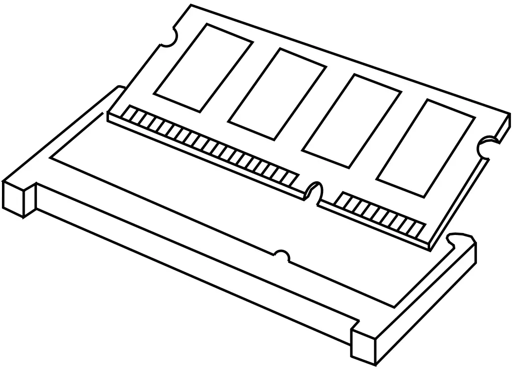
 The SO-DIMM only fits in one correct orientation. It will cause permanent damage to the motherboard and the SO-DIMM if you force the SO-DIMM into the slot at incorrect orientation.
- Please do not intermix different voltage SO-DIMMs on this motherboard.
Step 2. Firmly insert the SO-DIMM into the slot until the retaining clips at both ends fully snap back in place and the SO-DIMM is properly seated.
Expansion Slots (M.2 Slots)
There are 2 M.2 slots on this motherboard.
M.2 for SSD: 1 x M.2 (KEY M, 2242/2260/2280) with PCIe Gen4 x 4 * M.2 Key M 2280(Supported by bracket)
M.2 for Wi-Fi: 1 x M.2 (Key E, 2230) with PCIe x1, USB 2.0 for Wireless.
M.2 Key-M Socket (M2M_1)
| PIN | Signal Name | PIN | Signal Name | |||
| 1 | GND | 2 | +3.3V | |||
| 3 | GND | 4 | +3.3V | |||
| 5 | PERn3 | 6 | NA | |||
| 7 | PERp3 | 8 | NA | |||
| 9 | GND | 10 | LED | |||
| 11 | PETn3 | 12 | +3.3V | |||
| 13 | PETp3 | 14 | +3.3V | |||
| 15 | GND | 16 | +3.3V | |||
| 17 | PERn2 | 18 | +3.3V | |||
| 19 | PERp2 | 20 | NA | |||
| 21 | GND | 22 | NA | |||
| 23 | PETn2 | 24 | NA | |||
| 25 | PETp2 | 26 | NA | |||
| 27 | GND | 28 | NA | |||
| 29 | PERn1 | 30 | NA | |||
| 31 | PERp1 | 32 | NA | |||
| 33 | GND | 34 | USB_D+ | |||
| 35 | PETn1 | 36 | USB_D- | |||
| 37 | PETp1 | 38 | DEVSLP | |||
| 39 | GND | 40 | SMB_CLK | |||
| 41 | PERn0 | 42 | SMB_DATA | |||
| 43 | PERp0 | 44 | NA | |||
| 45 | GND | 46 | NA | |||
| 47 | PETn0 | 48 | NA | |||
| 49 | PETP0 | 50 | PERST# | |||
| 51 | GND | 52 | CLKREQ# | |||
| 53 | PEFCLKn | 54 | WAKE# | |||
| 55 | PEFCLKp | 56 | NA | |||
| 57 | GND | 58 | NA | |||
| 67 | NA | 68 | NA | |||
| 69 | PEDET | 70 | +3.3V | |||
| 71 | GND | 72 | +3.3V | |||
| 73 | GND | 74 | +3.3V | |||
| 75 | GND | |||||
| PIN | Signal Name | PIN | Signal Name | |||
| 1 | GND | 2 | +3.3V | |||
| 3 | USB_D+ | 4 | +3.3V | |||
| 5 | USB_D- | 6 | NA | |||
| 7 | GND | 8 | NA | |||
| 9 | NA | 10 | NA | |||
| 11 | NA | 12 | NA | |||
| 13 | NA | 14 | NA | |||
| 15 | NA | 16 | NA | |||
| 17 | NA | 18 | GND | |||
| 19 | NA | 20 | NA | |||
| 21 | NA | 22 | NA | |||
| 23 | NA | |||||
| 33 | GND | 32 | NA | |||
| 35 | PETp | 34 | NA | |||
| 37 | PETn | 36 | NA | |||
| 39 | GND | 38 | NA | |||
| 41 | PERp | 40 | NA | |||
| 43 | PERn | 42 | NA | |||
| 45 | GND | 44 | NA | |||
| 47 | PEFCLKp | 46 | NA | |||
| 49 | PEFCLKn | 48 | NA | |||
| 51 | GND | 50 | SUSCLK | |||
| 53 | CLKREQ# | 52 | PERST0# | |||
| 55 | WAKE# | 54 | W_DISABLE1# | |||
| 57 | GND | 56 | W_DISABLE2# | |||
| 59 | NA | 58 | SMB_DATA | |||
| 61 | NA | 60 | SMB_CLK | |||
| 63 | GND | 62 | NA | |||
| 65 | NA | 64 | NA | |||
| 67 | NA | 66 | NA | |||
| 69 | GND | 68 | NA | |||
| 71 | NA | 70 | NA | |||
| 73 | NA | 72 | +3.3V | |||
| 75 | GND | 74 | +3.3V | |||
- Pin6 and Pin8 are defined as USB 2.0 signal to support Key-M to Key-B extension card.
Onboard Headers and Connectors
Onboard headers and connectors are NOT jumpers. Do NOT place jumper caps over these headers and connectors. Placing jumper caps over the headers and connectors will cause permanent damage to the motherboard!
USB 2.0 Connector
(9-pin USB2H_2_3) (see p.8, No. 3)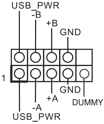
There is one USB 2.0 connector on this motherboard. The power supply is 5V and the maximum power current support is 0.5A.
COM Port Header (RS232/422/485)
(9-pin COM1) (see p.8, No. 4)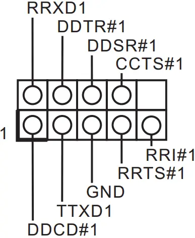
- This motherboard supports RS232/422/485 on COM1 port. Please refer to table below for the pin definition. In addition, COM1 port (RS232/422/485) can be adjusted in BIOS setup utility > Advanced Screen > Super IO Configuration. You may refer to our manual for details.
COM1 Port Pin Definition
| PIN | RS232 | RS422 | RS485 |
| 1 | DCD, Data Carrier Detect | TX- | RTX- |
| 2 | RXD, Receive Data | TX+ | RTX+ |
| 3 | TXD, Transmit Data | RX+ | N/A |
| 4 | DTR, Data Terminal Ready | RX- | N/A |
| 5 | GND | GND | GND |
| 6 | DSR, Data Set Ready | N/A | N/A |
| 7 | RTS, Request To Send | N/A | N/A |
| 8 | CTS, Clear To Send | N/A | N/A |
| 9 | N/A | N/A | N/A |
SATA3 Port
(SATA3_1) (see p.8, No. 5)
The Serial ATA3 (SATA3) connector supports SATA data cables for internal storage devices. The current SATA3 interface allows up to 6.0 Gb/s data transfer rate.
| PIN | Signal Name |
| 20 | GND |
| 19 | GND |
| 18 | GND |
| 17 | NC |
| 16 | +5V |
| 15 | +5V |
| 14 | +5V |
| 13 | +5V |
| 12 | +5V |
| 11 | NC |
| 10 | GND |
| 9 | GND |
| 8 | GND |
| 7 | R_SATA_RXP0 |
| 6 | R_SATA_RXN0 |
| 5 | GND |
| 4 | GND |
| 3 | R_SATA_TXN0 |
| 2 | R_SATA_TXP0 |
| 1 | GND |
JP1 Header
(JP1) (see p.8, No. 6)
JP1_12: SIO AT Mode
JP1_34: CMOS Normal (Default)
JP1_46: Clear CMOS
JP1_57: Reserved for AT mode
System Panel Header
(9-pin PANEL1) (see p.8, No. 7)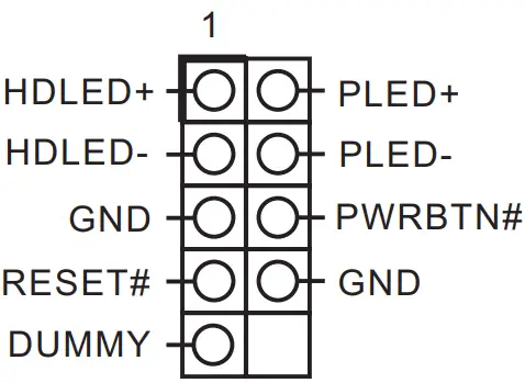
This header accommodates several system front panel functions
Connect the power switch, reset switch and system status indicator on the chassis to this header according to the pin assignments below. Note the positive and negative pins before connecting the cables.
PWRBTN (Power Switch):
Connect to the power switch on the chassis front panel. You may configure the way to turn off your system using the power switch.
RESET (Reset Switch):
Connect to the reset switch on the chassis front panel. Press the reset switch to restart the computer if the computer freezes and fails to perform a normal restart.
PLED (System Power LED):
Connect to the power status indicator on the chassis front panel. The LED is on when the system is operating. The LED keeps blinking when the system is in S1 sleep state. The LED is off when the system is in S3/S4 sleep state or powered off (S5).
HDLED (Hard Drive Activity LED):
Connect to the hard drive activity LED on the chassis front panel. The LED is on when the hard drive is reading or writing data.
The front panel design may differ by chassis. A front panel module mainly consists of power switch, reset switch, power LED, hard drive activity LED, speaker and etc. When connecting your chassis front panel module to this header, make sure the wire assignments and the pin assign-ments are matched correctly.
Back Side:
Power Button Header
(PWR_BTN1)(see p.9, No. 8)
Fan Connector
(FAN1)(see p.9, No. 9)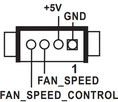
Battery Connector
(BAT1) (see p.9, No. 10)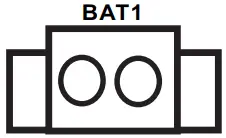
ESPI Connector
(ESPI1) (see p.9, No. 11)
| PIN | Signal Name |
| 1 | GND |
| 2 | ESPI_CLK |
| 3 | GND |
| 4 | ESPI_CS1# |
| 5 | ESPI_RESET# |
| 6 | GND |
| 7 | +3V |
| 8 | GND |
| 9 | SMB_CLK_MAIN_3V |
| 10 | SMB_DATA_MAIN_3V |
| 11 | ESPI_DAT0 |
| 12 | ESPI_DAT1 |
| 13 | ESPI_DAT2 |
| 14 | ESPI_DAT3 |
| 15 | GND |
| 16 | +3VSB |
| 17 | GPIO_TEST# |
| 18 | GND |
| 19 | ESPI_ALERT# |
| 20 | GND |
UEFI SETUP UTILITY
Introduction
This section explains how to use the UEFI SETUP UTILITY to configure your system. The UEFI chip on the motherboard stores the UEFI SETUP UTILITY. You may run the UEFI SETUP UTILITY when you start up the computer. Please press or You may also restart by turning the system off and then back on.
Because the UEFI software is constantly being updated, the following UEFI setup screens and descriptions are for reference purpose only, and they may not exactly match what you see on your screen.
UEFI Menu Bar
The top of the screen has a menu bar with the following selections:
Main To set up the system time/date information
Advanced To set up the advanced UEFI features
H/W Monitor To display current hardware status
Security To set up the security features
Boot To set up the default system device to locate and load the Operating System
Exit To exit the current screen or the UEFI SETUP UTILITY
Use < > key or < > key to choose among the selections on the menu bar, and then press to get into the sub screen. You can also use the mouse to click your required item.
Navigation Keys
Please check the following table for the function description of each navigation key.
Main Screen
When you enter the UEFI SETUP UTILITY, the Main screen will appear and display the system overview.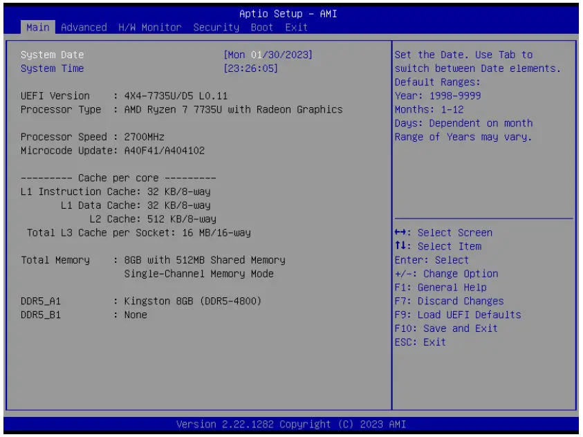
Advanced Screen
In this section, you may set the configurations for the following items: CPU Configuration, Chipset Configuration, Storage Configuration, Super IO Configuration, ACPI Configuration, USB Configuration, and Trusted Computing.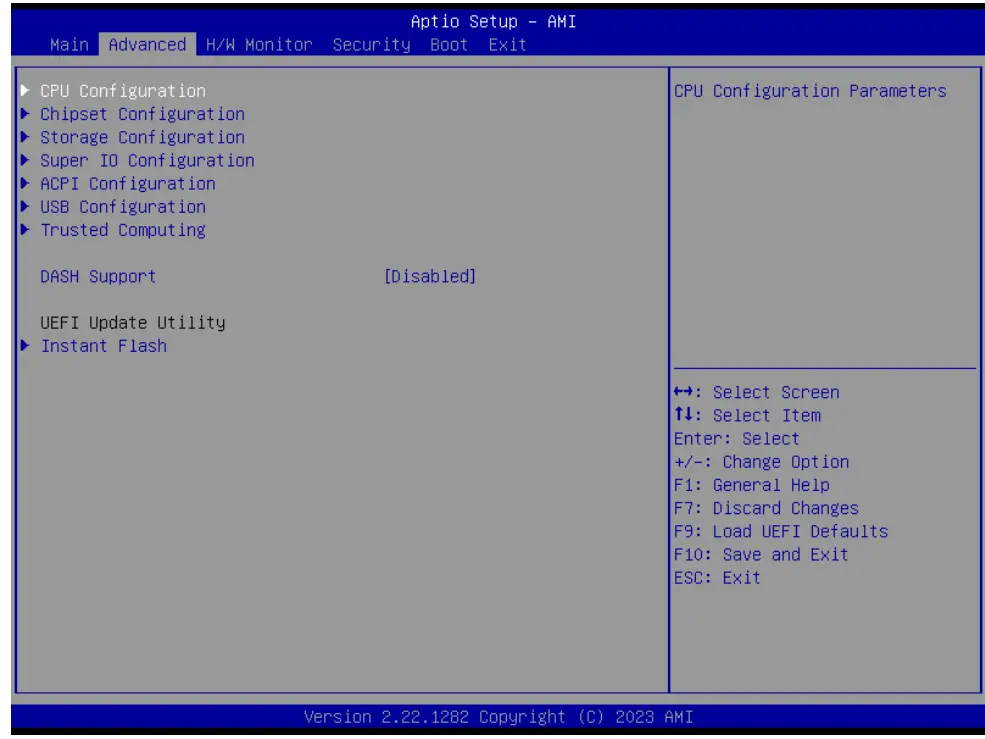
Setting wrong values in this section may cause the system to malfunction.
DASH Support
Enable or disable Realtek Lan DASH Function.
Instant Flash
Instant Flash is a UEFI flash utility embedded in Flash ROM. This convenient UEFI update tool allows you to update system UEFI without entering operating systems first like MS-DOS or Windows® . Just launch this tool and save the new UEFI file to your USB flash drive, floppy disk or hard drive, then you can update your UEFI only in a few clicks without preparing an additional floppy diskette or other complicated flash utility. Please be noted that the USB flash drive or hard drive must use FAT32/16/12 file system. If you execute Instant Flash utility, the utility will show the UEFI files and their respective information. Select the proper UEFI file to update your UEFI, and reboot your system after UEFI update process completes.
CPU Configuration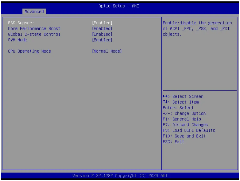
PSS Support
Enable/disable the generation of ACPI _PPC, _PSS, and _PCT objects.
Core Performance Boost
Core Performance Boost controls whether the processor transitions to a higher frequency than the processor’s rated speed if the processor has available power and is within temperature specifications. The default valueis [Enabled].
Global C-state Control
Enable/Disable Global C-state Control.
SVM Mode
When this is set to [Enabled], a VMM (Virtual Machine Architecture) can utilize the additional hardware capabilities provided by AMD-V. The default value is [Enabled]. Configuration options: [Enabled] and [Disabled].
CPU Operation Mode
If working at [Normal Mode], M/B works with the default Smart Fan Setting and can provide better cooler experience. If [Performance Mode] is selected, CPU can provide optimal performance, but the CPU fan speed will work at higher speed.
Chipset Configuration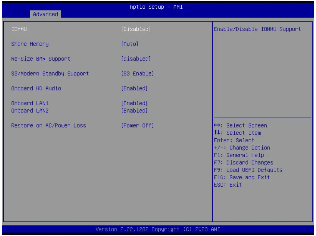
IOMMU
Enable/Disable IOMMU Support.
Share Memory
Configure the size of memory that is allocated to the integrated graphics processor when the system boots up.
Re-Size BAR Support
If the system has Resizable BAR capable PCIe Devices, this option enables or disables Resizable BAR Support.
S3/Modern Standby Support
Switch S3/Modern Standby.
Onboard HD Audio
Select [Enabled] or [Disabled] for the onboard HD Audio feature.
Onboard LAN 1
This allows you to enable or disable the Onboard LAN 1.
Onboard LAN 2
This allows you to enable or disable the Onboard LAN 2.
Restore on AC/Power Loss
Select the power state after a power failure. If [Power Off] is selected, the power will remain off when the power recovers. If [Power On] is selected, the system will start to boot up when the power recovers.
Storage Configuration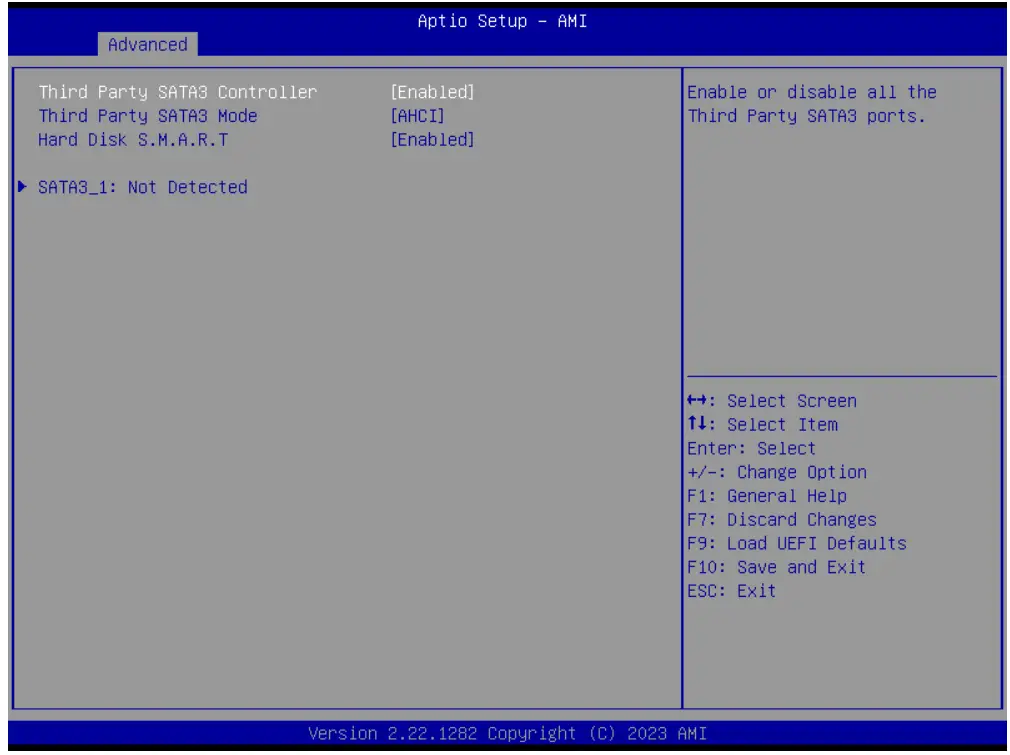
Third Party SATA3 Controller
The option allows you to enable or disable the SATA controllers. Configuration options: [Enabled] [Disabled]
Third Party SATA3 Mode
AHCI supports new features that improve performance. Configuration option: [AHCI]
AHCI (Advanced Host Controller Interface) supports NCQ and other new features that will improve SATA disk performance but IDE mode does not have these advantages.
Hard Disk S.M.A.R.T.
Use this item to enable or disable the S.M.A.R.T. (Self-Monitoring, Analysis, and Reporting Technology) feature. Configuration options: [Disabled] and [Enabled].
Super IO Configuration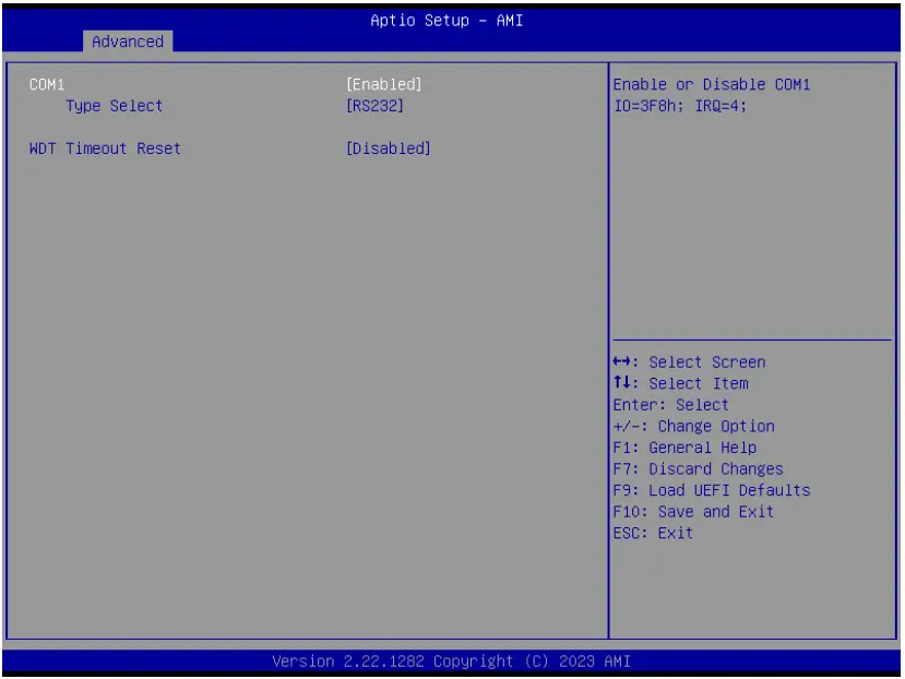
COM1 Configuration
Use this to set parameters of COM1.
Type Select
Use this to select COM1 port type: [RS232], [RS422] or [RS485].
WDT Timeout Reset
Use this to set the Watch Dog Timer.
ACPI Configuration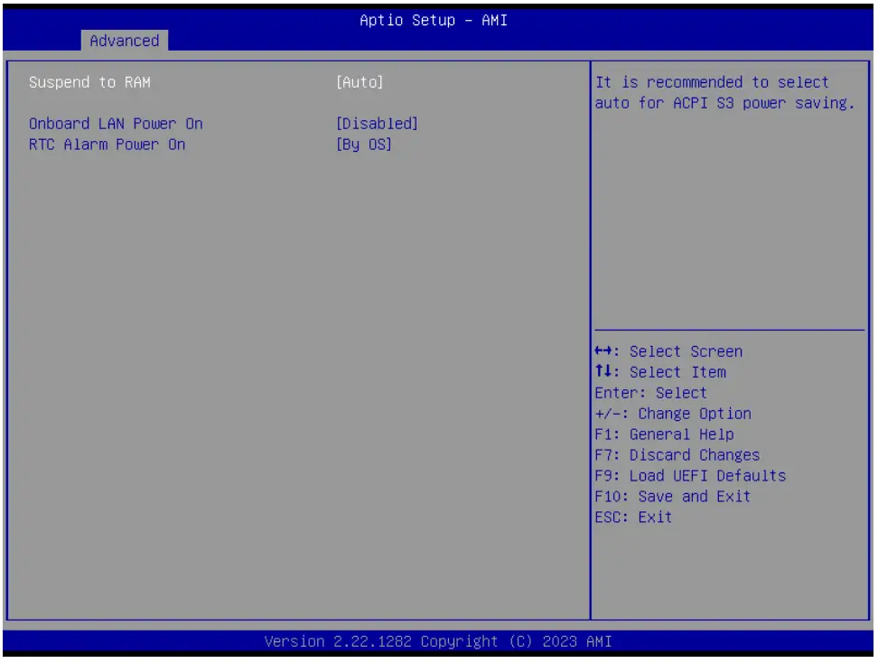
Suspend to RAM
Use this item to select whether to auto-detect or disable the Suspend-toRAM feature. Select [Auto] will enable this feature if the OS supports it.
Onboard LAN Power On
Use this item to enable or disable onboard LAN to turn on the system from the power-soft-off mode.
RTC Alarm Power On
Use this item to enable or disable RTC (Real Time Clock) to power on the system.
USB Configuration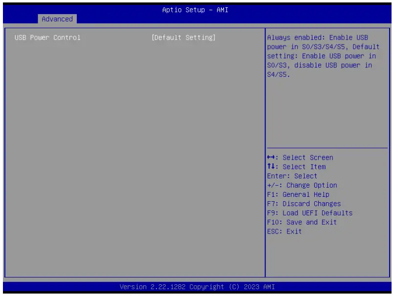
USB Power Control
Use this to control USB power. The default value is [Default Setting].
Trusted Computing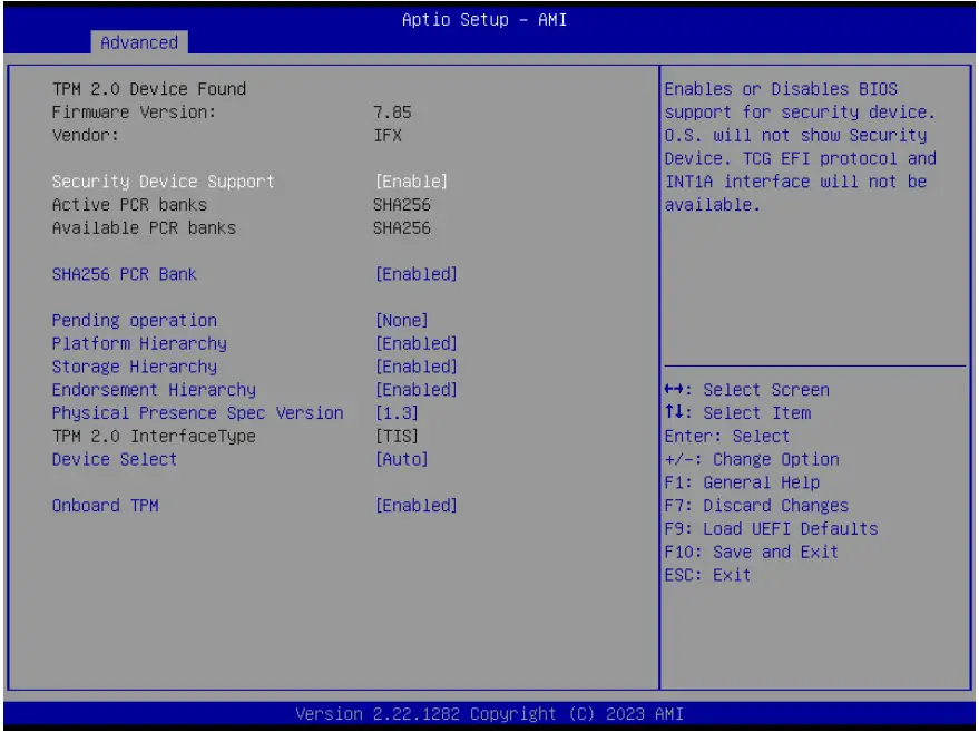
Security Device Support
Security Device Support allows you to enable or disable BIOS support for security device. O.S. will not show Security Device. TCG EFI protocol and INT1A interface will not be available. Configuration options: [Enabled] [Disabled]
Active PCR banks
This item displays active PCR Banks.
Available PCR Banks
This item displays available PCR Banks.
SHA256 PCR Bank
SHA256 PCR Bank allows you to enable or disable SHA256 PCR Bank. Configuration options: [Enabled] [Disabled]
Pending Operation
Pending Operation allows you to schedule an Operation for the Security Device.
NOTE: Your computer will reboot during restart in order to change State of the Device. Configuration options: [None] [TPM Clear]
Platform Hierarchy
This item allows you to enable or disable Platform Hierarchy. Configuration options: [Enabled] [Disabled]
Storage Hierarchy
This item allows you to enable or disable Storage Hierarchy. Configuration options: [Enabled] [Disabled]
Endorsement Hierarchy
This item allows you to enable or disable Endorsement Hierarchy. Configuration options: [Enabled] [Disabled]
Physical Presence Spec Version
Select this item to tell OS to support PPI spec version 1.2 or 1.3. Please note that some HCK tests might not support version 1.3. Configuration options: [1.2] [1.3]
TPM 2.0 InterfaceType
This item allows you to view the Communication Interface to TPM 2.0 Device: CRB or ITS.
Device Select
This item allows you to select the TPM device to be supported.
[TPM 1.2] restricts support to TPM 1.2 devices. [TPM 2.0] restricts support to TPM 2.0 devices. [Auto] supports both TPM 1.2 and TPM 2.0 devices with the default set to TPM 2.0 devices. If TPM 2.0 devices are not found, TPM 1.2 devices will be enumerated.
Onboard TPM
Disable this option to use discrete TPM Module.
Hardware Health Event Monitoring Screen
In this section, it allows you to monitor the status of the hardware on your system, including the parameters of the CPU temperature, motherboard temperature, fan speed, and the critical voltage.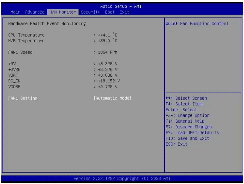
FAN1 Setting
This allows you to set FAN1’s speed. Configuration options: [Full On], [Manual] and [Automatic Mode]. The default value is [Automatic Mode].
Security Screen
In this section, you may set, change or clear the supervisor/user password for the system.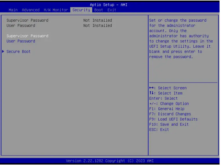
Supervisor Password
Set or change the password for the administrator account. Only the administrator has authority to change the settings in the UEFI Setup Utility. Leave it blank and press enter to remove the password.
User Password
Set or change the password for the user account. Users are unable to change the settings in the UEFI Setup Utility. Leave it blank and press enter to remove the password.
Secure Boot
Enable to support Windows Secure Boot.
Boot Screen
In this section, it will display the available devices on your system for you to configure the boot settings and the boot priority.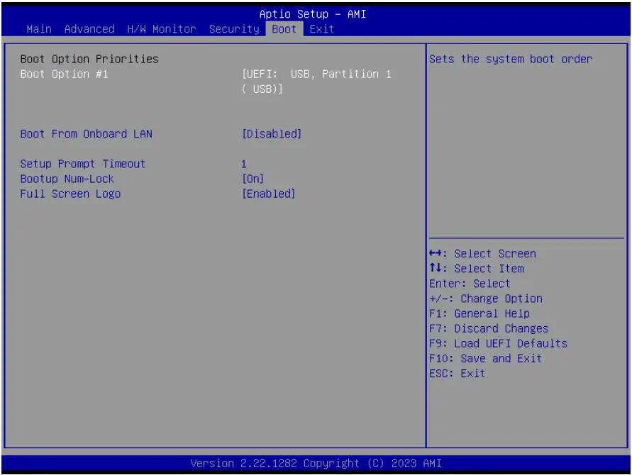
Boot From Onboard LAN
Use this item to enable or disable the Boot From Onboard LAN feature.
Setup Prompt Timeout
This shows the number of seconds to wait for setup activation key. 65535(0XFFFF) means indefinite waiting.
Bootup Num-Lock
If this item is set to [On], it will automatically activate the Numeric Lock function after boot-up.
Full Screen Logo
Use this item to enable or disable OEM Logo. The default value is [Enabled].
Exit Screen
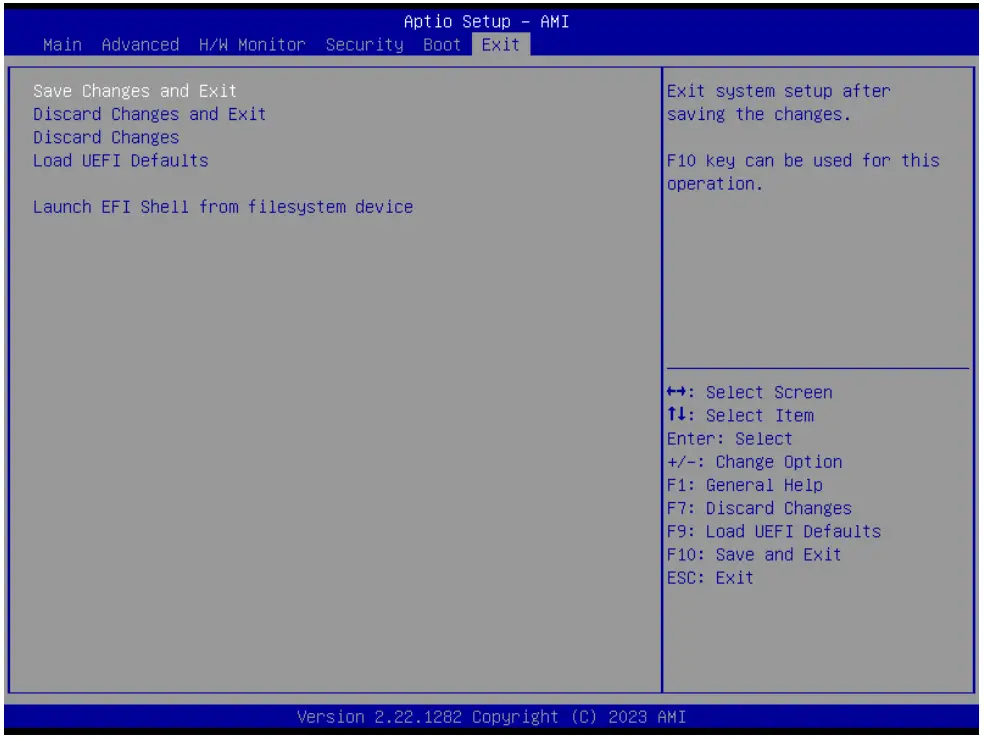
Save Changes and Exit
When you select this option, it will pop-out the following message, “Save configuration changes and exit setup?” Select [OK] to save the changes and exit the UEFI SETUP UTILITY.
Discard Changes and Exit
When you select this option, it will pop-out the following message, “Discard changes and exit setup?” Select [OK] to exit the UEFI SETUP UTILITY without saving any changes.
Discard Changes
When you select this option, it will pop-out the following message, “Discard changes?” Select [OK] to discard all changes.
Load UEFI Defaults
Load UEFI default values for all the setup questions. F9 key can be used for this operation.
Launch EFI Shell from filesystem device
Attempts to Launch EFI Shell application (Shell64.efi) from one of the available filesystem devices.
Software Support
Install Operating System
This motherboard supports various Microsoft® Windows® operating systems: 10 64-bit. Because motherboard settings and hardware options vary, use the setup procedures in this chapter for general reference only. Refer your OS documentation for more information.