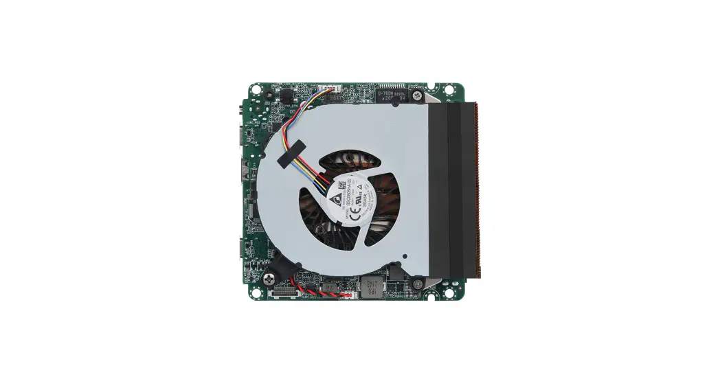
![]() 4X4-7735U/D5 4X4-7535U/D5
4X4-7735U/D5 4X4-7535U/D5
Jumpers and Headers Setting Guide
4X4-7735U/D5 Jumpers and Headers
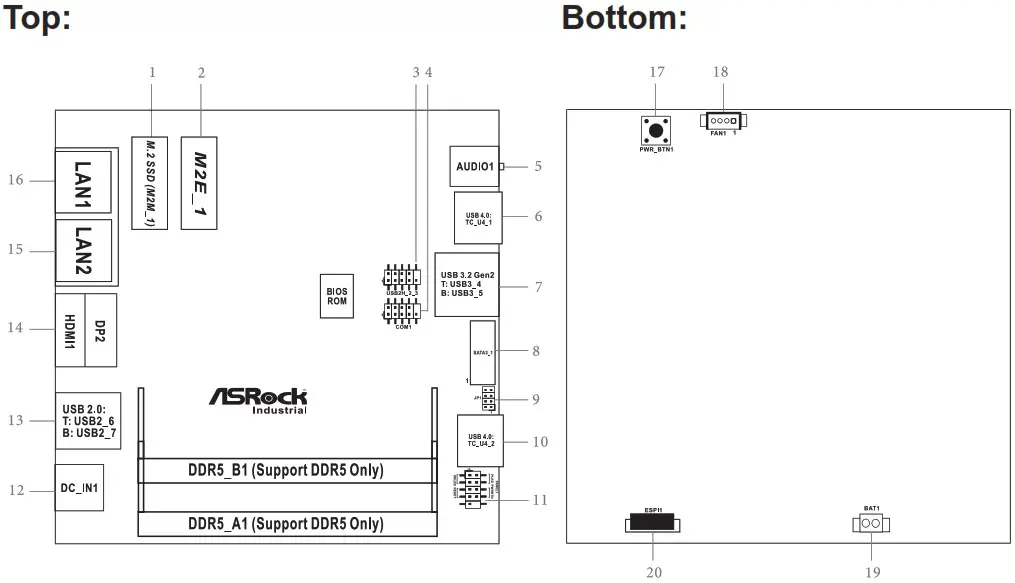
1 : M.2 Key-M Socket (M2M_1)
| PIN | Signal Name | PIN | Signal Name |
| 1 | GND | 2 | +3.3V |
| 3 | GND | 4 | +3.3V |
| 5 | PERn3 | 6 | USB_D+ |
| 7 | PERp3 | 8 | USB_D- |
| 9 | GND | 10 | LED |
| 11 | PETn3 | 12 | +3.3V |
| 13 | PETp3 | 14 | +3.3V |
| 15 | GND | 16 | +3.3V |
| 17 | PERn2 | 18 | +3.3V |
| 19 | PERp2 | 20 | NA |
| 21 | GND | 22 | NA |
| 23 | PETn2 | 24 | NA |
| 25 | PETp2 | 26 | NA |
| 27 | GND | 28 | NA |
| 29 | PERn1 | 30 | NA |
| 31 | PERp1 | 32 | NA |
| 33 | GND | 34 | NA |
| 35 | PETn1 | 36 | NA |
| 37 | PETp1 | 38 | DEVSLP |
| 39 | GND | 40 | SMB_CLK |
| 41 | PERn0 | 42 | SMB_DATA |
| 43 | PERp0 | 44 | NA |
| 45 | GND | 46 | NA |
| 47 | PETn0 | 48 | NA |
| 49 | PETP0 | 50 | PERST# |
| 51 | GND | 52 | CLKREQ# |
| 53 | PEFCLKn | 54 | WAKE# |
| 55 | PEFCLKp | 56 | NA |
| 57 | GND | 58 | NA |
| 67 | NA | 68 | NA |
| 69 | PEDET | 70 | +3.3V |
| 71 | GND | 72 | +3.3V |
| 73 | GND | 74 | +3.3V |
| 75 | GND |
* Pin6 and Pin8 are defined as USB2.0 signal to support Key-M to Key-B extension card.
2 : M.2 Key-E Socket (M2E_1)
| PIN | Signal Name | PIN | Signal Name |
| 1 | GND | 2 | +3.3V |
| 3 | USB_D+ | 4 | +3.3V |
| 5 | USB_D- | 6 | NA |
| 7 | GND | 8 | NA |
| 9 | NA | 10 | NA |
| 11 | NA | 12 | NA |
| 13 | NA | 14 | NA |
| 15 | NA | 16 | NA |
| 17 | NA | 18 | GND |
| 19 | NA | 20 | NA |
| 21 | NA | 22 | NA |
| 23 | NA | ||
| 33 | GND | 32 | NA |
| 35 | PETp | 34 | NA |
| 37 | PETn | 36 | NA |
| 39 | GND | 38 | NA |
| 41 | PERp | 40 | NA |
| 43 | PERn | 42 | NA |
| 45 | GND | 44 | NA |
| 47 | PEFCLKp | 46 | NA |
| 49 | PEFCLKn | 48 | NA |
| 51 | GND | 50 | SUSCLK |
| 53 | CLKREQ# | 52 | PERST0# |
| 55 | WAKE# | 54 | W_DISABLE1# |
| 57 | GND | 56 | W_DISABLE2# |
| 59 | NA | 58 | SMB_DATA |
| 61 | NA | 60 | SMB_CLK |
| 63 | GND | 62 | NA |
| 65 | NA | 64 | NA |
| 67 | NA | 66 | NA |
| 69 | GND | 68 | NA |
| 71 | NA | 70 | NA |
| 73 | NA | 72 | +3.3V |
| 75 | GND | 74 | +3.3V |
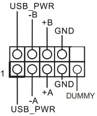
3 : USB2.0 Connector (USB2H_2_3)
4 : COM Port Header (RS232/422/485)
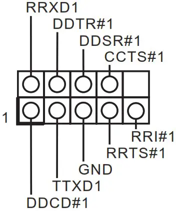
* This motherboard supports RS232/422/485 on COM1 port. Please refer to below table for the pin definition. In addition, COM1 port (RS232/422/485) can be adjusted in BIOS setup utility > Advanced Screen > Super IO Configuration. You may refer to our user manual for details.
COM1 Port Pin Definition
| PIN | RS232 | RS422 | RS485 |
| 1 | DCD, Data Carrier Detect | TX- | RTX- |
| 2 | RXD, Receive Data | TX+ | RTX+ |
| 3 | TXD, Transmit Data | RX+ | N/A |
| 4 | DTR, Data Terminal Ready | RX- | N/A |
| 5 | GND | GND | GND |
| 6 | DSR, Data Set Ready | N/A | N/A |
| 7 | RTS, Request To Send | N/A | N/A |
| 8 | CTS, Clear To Send | N/A | N/A |
| 9 | N/A | N/A | N/A |
5 : Audio Jack (AUDIO1)
6 : USB 4.0 Type-C Port (TC_U4_1)
7 : USB 3.2 Gen2 Ports (USB3_4_5)
8 : SATA3 Port (SATA3_1)
| PIN | Signal Name |
| 20 | GND |
| 19 | GND |
| 18 | GND |
| 17 | NC |
| 16 | +5V |
| 15 | +5V |
| 14 | +5V |
| 13 | +5V |
| 12 | +5V |
| 11 | NC |
| 10 | GND |
| 9 | GND |
| 8 | GND |
| 7 | R_SATA_RXP0 |
| 6 | R_SATA_RXN0 |
| 5 | GND |
| 4 | GND |
| 3 | R_SATA_TXN0 |
| 2 | R_SATA_TXP0 |
| 1 | GND |
9 : JP1
JP1_12 : SIO AT Mode
JP1_34 : CMOS Normal
JP1_46 : Clear CMOS
10 : USB 4.0 Type-C Port (TC_U4_2)
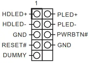
11 : System Panel Header (PANEL1)
12 : DC-In Jack (DC_IN1)
13 : USB 2.0 Ports (USB2_6_7)
14 : Top : DisplayPort (DP2) Bottom : HDMI Port (HDMI1)
15 : RJ-45 LAN Port (LAN2)
16 :RJ-45 LAN Port (LAN1)
Back Side :
17 : Power Button (PWR_BTN1) ![]()
18 : Fan Connector (FAN1)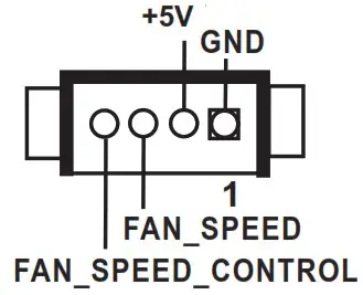 19 : Battery Connector (BAT1)
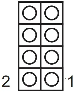
20 : ESPI Connector (ESPI1)![]()
| PIN | Signal Name |
| 1 | GND |
| 2 | ESPI_CLK |
| 3 | GND |
| 4 | ESPI_CS1# |
| 5 | ESPI_RESET# |
| 6 | GND |
| 7 | +3V |
| 8 | GND |
| 9 | SMB_CLK_MAIN_3V |
| 10 | SMB_DATA_MAIN_3V |
| 11 | ESPI_DAT0 |
| 12 | ESPI_DAT1 |
| 13 | ESPI_DAT2 |
| 14 | ESPI_DAT3 |
| 15 | GND |
| 16 | +3VSB |
| 17 | GPIO_TEST# |
| 18 | GND |
| 19 | ESPI_ALERT# |
| 20 | GND |
Installation of ROM Socket
![]()
* Do not apply force to the actuator cover after ic inserted.
* Do not apply force to actuator cover when it is opening over 120 degree, Otherwise, the actuator cover may be broken.
![]()
* The yellow dot (Pin1) on the ROM must be installed at pin1 position of the socket (white arrow area).
* Make sure the white dot on the ROM is installed outwards of the socket.
* For further details of how to install ROM, please refer to ASRI website.
Warning: If the installation does not follow as the picture, then it may cause severe damage to chipset & MB.
![]()


