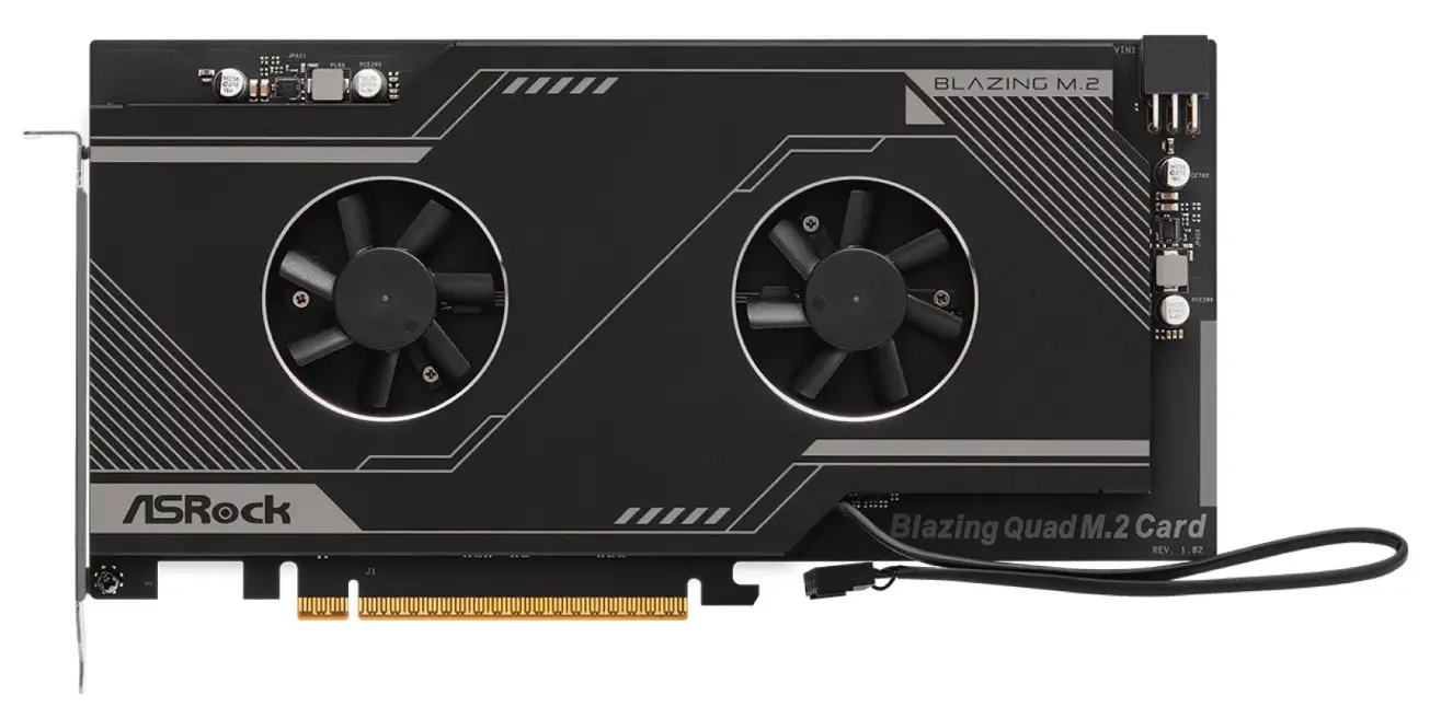
ASRock Blazing Quad M.2 Card

Package Contents
- ASRock Blazing Quad M.2 Card
- User Manual
- M.2 screws
Specifications
| Dimensions |
|
| Interface |
|
| Connector |
|
- For the M.2 SSD support list and the list of supported motherboard models, please visit www.asrock.com.
Installation Procedure
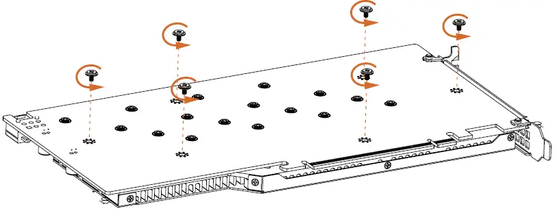
- Remove the six screws holding the bracket in place.

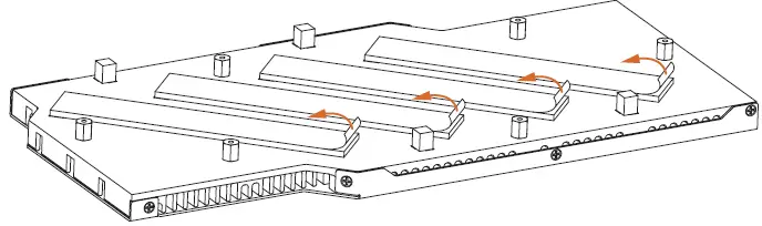
- Peel off the protective film(s) on the bracket’s thermal pad(s) before you install M.2 SSD module(s).

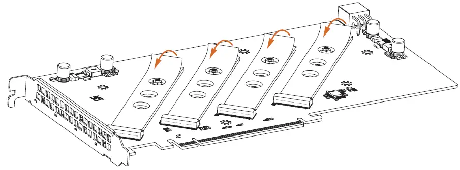
- Peel off the protective film(s) on the Blazing Quad M.2 Card’s thermal pad(s) before you install M.2 SSD module(s).

- Fasten the six screws holding the bracket in place. Power off the PC and unplug the power cord. Detach all other cables from the PC.
- Remove the PC cover.
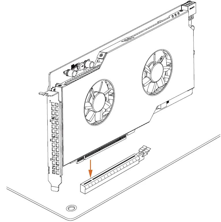
- Align and insert the card into a PCI Express 5.0 x16 slot on the motherboard. Press firmly until the card is securely seated in place.

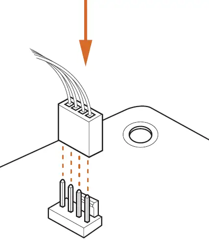
- Plug the attached fan cable to a free fan connector on your motherboard.

Card Layout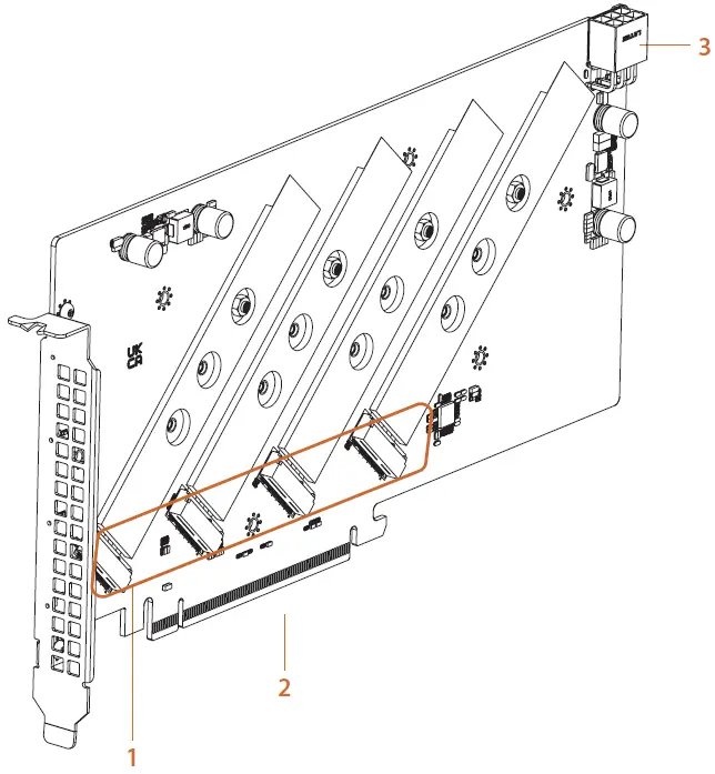
| No. | Description |
| 1 | Blazing M.2 Sockets |
| 2 | PCI Express 5.0 x 16 Interface |
| 3 | Graphics 12V Power Connector |
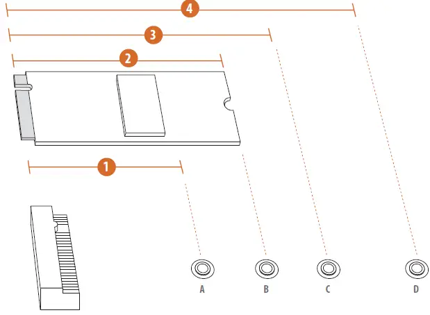
Installing M.2 SSD Module
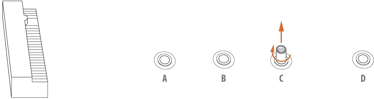
- Depending on the PCB type and length of your M.2 SSD module, find the corresponding nut location to be used.

No. 1 2 3 4 Nut Location A B C D PCB Length 4.2cm 6cm 8cm 11cm Module Type Type 2242 Type2260 Type 2280/2580 Type 22110/25110 - Move the standoff based on the module type and length. The standoff is placed at the nut location C by default. Skip Step 3 and 4 and go straight to Step 5 if you are going to use the default nut. Otherwise, release the standoff by hand.

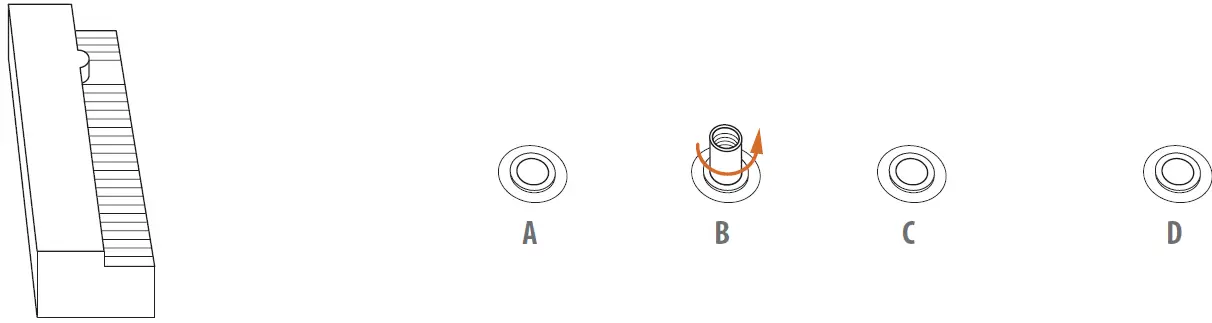
- Hand tighten the standoff into the desired nut location on the motherboard.

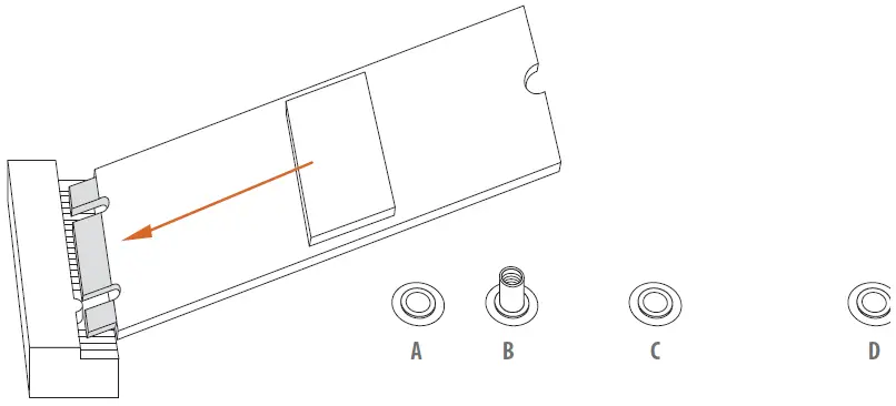
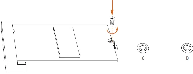
- Gently insert the M.2 SSD module into the M.2 slot.
Please be aware that the M.2 SSD module only fits in one orientation.

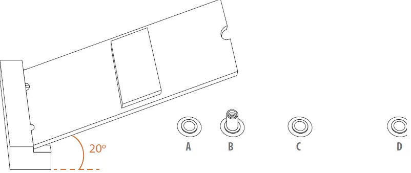
- Tighten the screw with a screwdriver to secure the module into place. Please do not overtighten the screw as this might damage the module.
Compatible ASRock Motherboard Models:
| Chipset | Motherboard Models | Supported PCIE slot | M.2 Slot | |||
| M2_1 | M2_2 | M2_3 | M2_4 | |||
| Intel W790 | W790 WS | PCIE1 | V | V | V | V |
| PCIE2 | V | V | ||||
| AMD WRX80* | WRX80 Creator / WRX80 Creator R2.0 | PCIE1/PCIE2/ PCIE3/PCIE5/PCIE7 | V | V | V | V |
| PCIE4/PCIE6 | V | V | ||||
| AMD X670 | X670E Taichi Carrara | PCIE1 | V | V | V | V |
| X670E Taichi | PCIE1 | V | V | V | V | |
| X670E Steel Legend | PCIE1 | V | V | V | V | |
| X670E Pro RS | PCIE1 | V | V | V | V | |
| X670E PG Lightning | PCIE1 | V | V | V | V | |
| AMD B650 | B650E Taichi | PCIE1 | V | V | V | V |
| B650E Steel Legend WiFi | PCIE1 | V | V | V | V | |
| B650E PG Riptide WiFi | PCIE1 | V | V | V | V | |
| B650E PG-ITX WiFi | PCIE1 | V | V | V | V | |
- This Platform will only operate at PCIe 4.0
For the updated information, please visit www.asrock.com.


