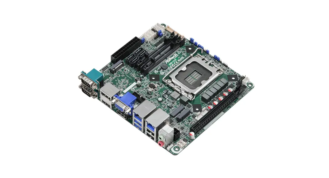
![]() IMB-1230 Mini-ITX Industrial Motherboards
IMB-1230 Mini-ITX Industrial Motherboards
User Guide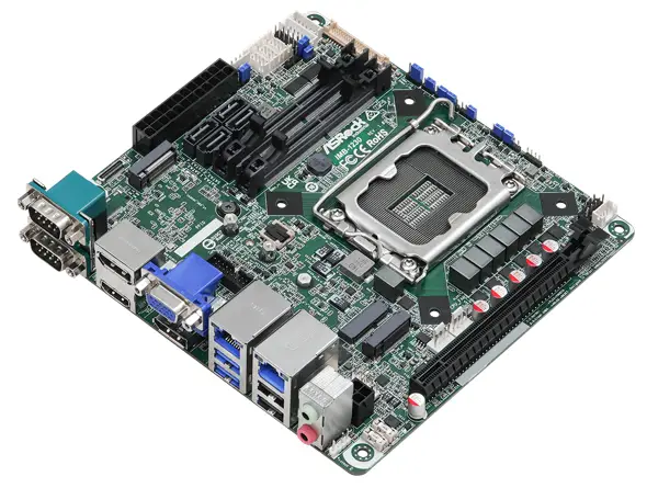
IMB-1230 Mini-ITX Industrial Motherboards
IMB-1230
The terms HDMI® and HDMI High-Definition
Multimedia Interface, and the HDMI logo are trademarks or registered trademarks of HDMI Licensing LLC in the United States and other countries.
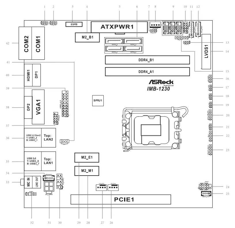
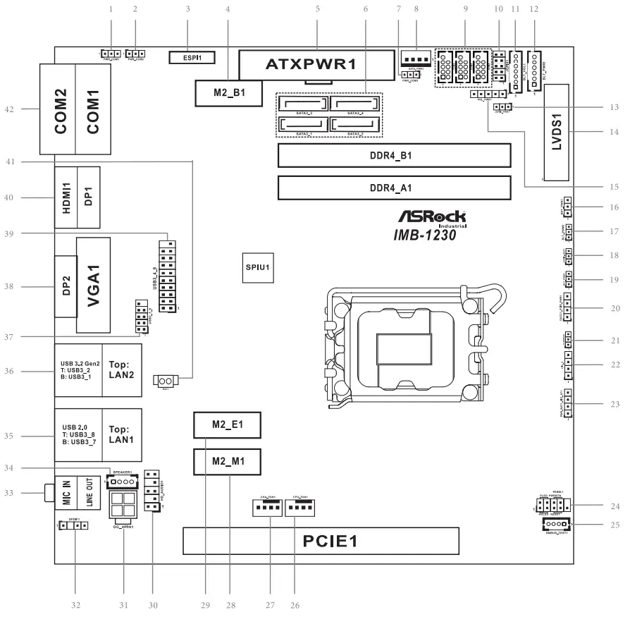
Jumpers and Headers Setting Guide
Revision History
| Date | Description |
| August 10, 202 | First Release |
COM Port PWR Setting Jumpers
- : PWR_COM1 (For COM Port1)
- : PWR_COM2 (For COM Port2)

- : ESPI Header (ESPI1)
- : M.2 Key-B Socket (M2_B1)
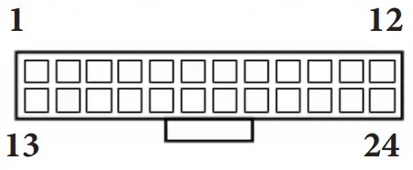
PIN Signal Signal PIN 1 NA +3.3V 2 3 GND +3.3V 4 5 GND FuLL_Card_Power_off 6 7 USB_D+ W_DISABLE 8 9 USB_D- WWAN_LED# 10 11 GND 21 GND NA 20 23 NA NA 22 25 NA NA 24 27 GND NA 26 29 USB3_RX- NA 28 31 USB3_RX+ UIM_RESET 30 33 GND UIM_CLK 32 35 USB3_TX- UIM_DATA 34 37 USB3_TX+ UIM_PWR 36 39 GND NA 38 41 PERn0 NA 40 43 PERp0 NA 42 45 GND NA 44 47 PETn0 NA 46 49 PETP0 NA 48 51 GND PERST# 50 53 PEFCLKn CLKREQ# 52 55 PEFCLKp NA 54 57 GND NA 56 59 NA NA 58 61 NA NA 60 63 NA NA 62 65 NA NA 64 67 NA NA 66 69 PEDET NA 68 71 GND +3.3V 70 73 GND +3.3V 72 75 NA +3.3V 74 - : 24-pin ATX Power Input Connector

- : SATA3 Connectors (SATA3_1~4)
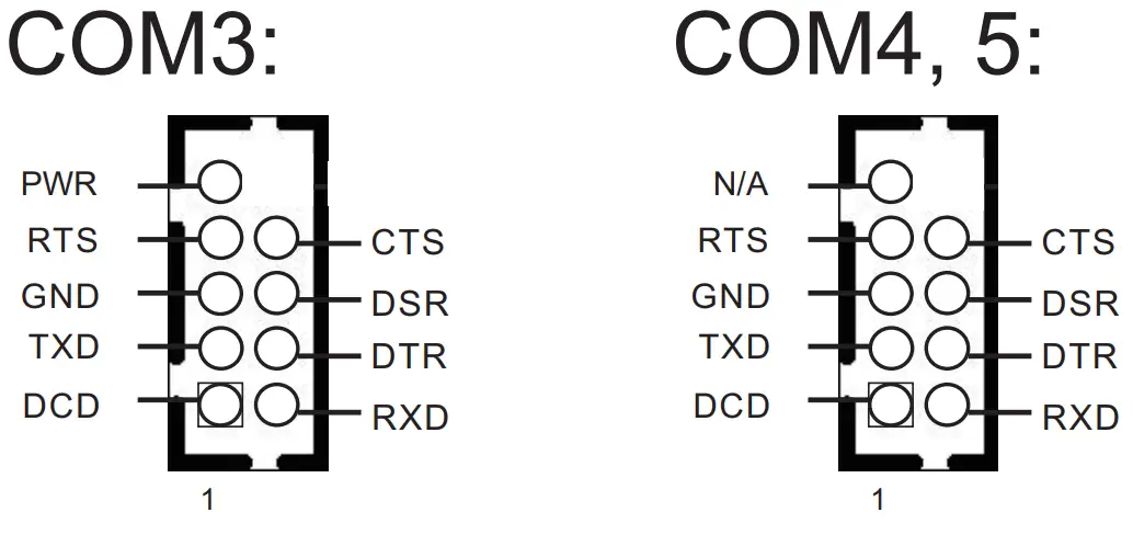
- : PWR_COM3 (For COM Port3)
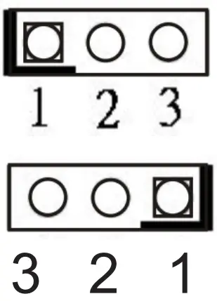
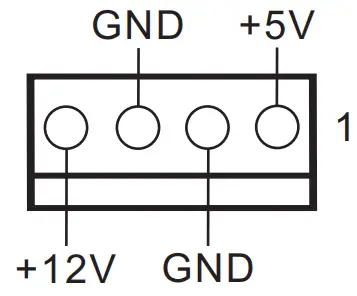
1-2: +5V
2-3: +12V - : SATA Power Output Connector

- : COM Port Headers (COM5, 4, 3) (RS232)

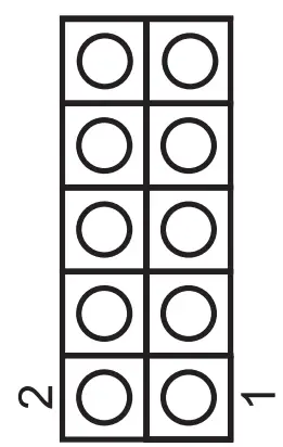
- : Digital Input/Output Pin Header (JGPIO1)

PIN Signal Name PIN Signal Name 10 GND 9 JGPIOPWR_R 8 GPP_E6 7 SIO_GP74 6 GPP_E5 5 SIO_GP73 4 GPP_I10 3 SIO_GP72 2 GPP_H23 1 SIO_GP71 - : Backlight Volume Control (BLT_VOL1)

PIN Signal Name 7 GND 6 GND 5 BLT_DW 4 BLT_UP 3 PWRDN 2 GPIO_VOL_DW 1 GPIO_VOL_UP - : Inverter Power Control Wafer (BLT_PWR1)
PIN Signal Name 6 LCD_BLT_VCC 5 LCD_BLT_VCC 4 CON_LBKLT_EN 3 CON_LBKLT_CTL 2 GND 1 GND - : Digital Input / Output Power Select (JGPIO_PWR1)
 1-2: +12V
2-3: +5V - : LVDS Panel Connector

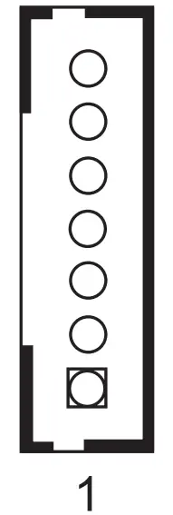
PIN Signal Name PIN Signal Name 39 LCD_BLT_VCC 40 LCD_BLT_VCC 37 CON_LBKLT_CTL 38 LCD_BLT_VCC 35 GND 36 CON_LBKLT_EN 33 LVDS_B_CLK# 34 LVDS_B_CLK 31 LVDS_B_DATA3 32 GND 29 DPLVDD_EN 30 LVDS_B_DATA3# 27 LVDS_B_DATA2# 28 LVDS_B_DATA2 25 LVDS_B_DATA1 26 GND 23 GND 24 LVDS_B_DATA1# 21 LVDS_B_DATA0# 22 LVDS_B_DATA0 19 LVDS_A_CLK 20 GND 17 GND 18 LVDS_A_CLK# 15 LVDS_A_DATA3# 16 LVDS_A_DATA3 13 LVDS_A_DATA2 14 GND 11 GND 12 LVDS_A_DATA2# 9 LVDS_A_DATA1# 10 LVDS_A_DATA1 7 LVDS_A_DATA0 8 GND 5 NA 6 LVDS_A_DATA0# 3 +3.3V 4 NA 1 LCD_VCC 2 LCD_VCC * eDP by pass mode pin definition (switch by BIOS):
PIN Signal Name PIN Signal Name 39 LCD_BLT_VCC 40 LCD_BLT_VCC 37 CON_LBKLT_CTL 38 LCD_BLT_VCC 35 GND 36 CON_LBKLT_EN 33 N/A 34 N/A 31 N/A 32 GND 29 DPLVDD_EN 30 N/A 27 N/A 28 N/A 25 N/A 26 GND 23 GND 24 N/A 21 N/A 22 N/A 19 EDP_AUXP 20 GND 17 GND 18 EDP_AUXN 15 N/A 16 N/A 13 EDP_TX0 14 GND 11 GND 12 EDP_TX0# 9 EDP_TX1# 10 EDP_TX1 7 N/A 8 GND 5 N/A 6 N/A 3 N/A 4 N/A 1 LCD_VCC 2 LCD_VCC - : Panel Power Select (LCD_VCC) (PNL_PWR1)1-2: LCD_VCC: +3V
2-3: LCD_VCC: +5V
4-5: LCD_VCC: +12V
- : Backlight Power Select
(LCD_BLT_VCC) (BKT_PWR1) 1-2: LCD_BLT_VCC: +5V 2-3: LCD_BLT_VCC: +12V
- : CON_LBKLT_CTL Voltage Level
(BLT_PWM2)
1-2: 3V Level
2-3: 5V Level
- : Digital Input / Output Default Value
Setting (JGPIO_SET1)
1-2: Pull-High
2-3: Pull-Low
- : Brightness Control Mode (BLT_PWM1)
1-2: From esp. PWM to CON_LBKLT_CTL
2-3: From LVDS PWM to CON_LBKLT_CTL* Please set to 1-2 when adjusting brightness by Brightness Control bar under OS.
* Please set to 2-3 when adjusting brightness by BLT_VOL1. - : DACC1_PCIE_PWR1
PIN1-2 Open: No ACC
PIN1-2 Short: ACC
PIN3: PSON#
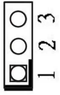
PIN4: GND * Auto clear CMOS when system boot improperly. - : Clear CMOS Header (CLRMOS1)
1-2: Normal
2-3: Clear CMOS - : Chassis Intrusion Header (CI1_2)
PIN 1-2 Open: Normal
PIN 1-2 Short: Active Case Open
PIN 3-4 Open: Active Case Open
PIN 3-4 Short: Normal - : PWR_BAT1_SIO_AT1
PIN 1-2 Open: Normal
PIN 1-2 Short: Charge Battery
PIN 3-4 Open: ATX Mode
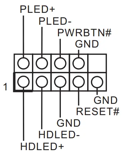
PIN 3-4 Short: AT Mode - : System Panel Header

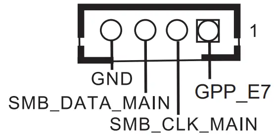
- : SMBUS_TEST1

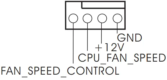
- : CPU FAN Connector (+12V)

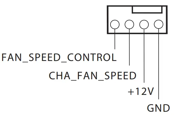
- : Chassis FAN Connector (+12V)

- : M.2 Key-M Socket (M2_M1)
PIN Signal Signal PIN 1 GND +3.3V 2 3 GND +3.3V 4 5 PERn3 NA 6 7 PERp3 NA 8 9 GND SATA_LED 10 11 PETn3 +3.3V 12 13 PETp3 +3.3V 14 15 GND +3.3V 16 17 PERn2 +3.3V 18 19 PERp2 NA 20 21 GND NA 22 23 PETn2 NA 24 25 PETp2 NA 26 27 GND NA 28 29 PERn1 NA 30 31 PERp1 NA 32 33 GND NA 34 35 PETn1 NA 36 37 PETp1 NA 38 39 GND SMB_CLK 40 41 PERn0 SMB_DATA 42 43 PERp0 NA 44 45 GND NA 46 47 PETn0 NA 48 49 PETP0 PERST# 50 51 GND CLKREQ# 52 53 PEFCLK n NA 54 55 PEFCLK p NA 56 57 GND NA 58 67 NA NA 68 69 PEDET +3.3V 70 71 GND +3.3V 72 73 GND +3.3V 74 75 GND - : M.2 Key-E Socket (M2_E1)
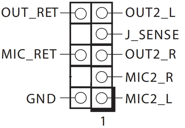
PIN Signal Signal PIN 1 GND +3.3V 2 3 USB_D+ +3.3V 4 5 USB_D- NA 6 7 GND NA 8 9 CNV_WGR_D1- CNV_RF_RESET 10 11 CNV_WGR_D1+ NA 12 13 GND MODEM_CLKRE 14 15 CNV_WGR_D0- NA 16 17 CNV_WGR_D0+ GND 18 19 GND NA 20 21 CNV_WGR_CLK- CNV_BRI_RSP 22 23 CNV_WGR_CLK+ 33 GND CNV_BGI_DT 32 35 PETp CNV_RGI_RSP 34 37 PETn CNV_BRI_DT 36 39 GND NA 38 41 PERp NA 40 43 PERn NA 42 45 GND NA 44 47 PEFCLKp NA 46 49 PEFCLKn NA 48 51 GND SUSCLK 50 53 CLKREQ# PERST0# 52 55 NA W_DISABLE1# 54 57 GND W_DISABLE2# 56 59 CNV_WT_D1- SMB_DATA 58 61 CNV_WT_D1+ SMB_CLK 60 63 GND NA 62 65 CNV_WT_D0- NA 64 67 CNV_WT_D0+ NA 66 69 GND NA 68 71 CNV_WT_CLK- NA 70 73 CNV_WT_CLK+ +3.3V 72 75 GND +3.3V 74 - : Front Panel Audio Header

- : 4-pin ATX PWR Connector
1-2: GND
3-4: DC Input
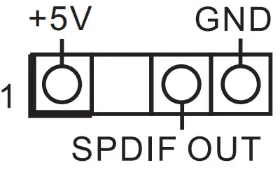
- : SPDIF Header

- : Audio Output
Green – Line Out
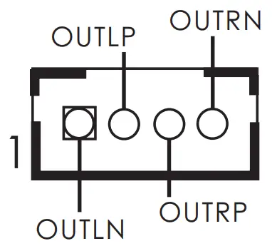
Pink – Mic In - : 3W Audio AMP Output Wafer

- : Top: RJ45 LAN Port (LAN1) Bottom: USB2.0 Ports (USB3_7_8)
- : Top: RJ45 LAN Port (LAN2) Bottom: USB3.2 Gen2 Ports (USB3_1_2)
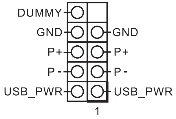
- : USB2.0 Header (USB2_5_6)

- : Top: D-Sub Port (VGA1) Bottom: DisplayPort (DP2)
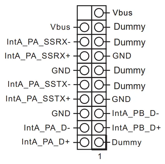
- : USB3.2 Gen1 Header (USB3_4_9)

- : Top: DisplayPort (DP1) Bottom: HDMI Port (HDMI1)
- : Battery Connector

- : COM Port Headers (COM1, 2) (RS232/422/485)
 1-2: +12V
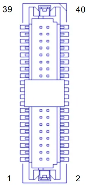


* This motherboard supports RS232/422/485 on COM1, 2 ports.
Please refer to below table for the pin definition. In addition, COM1, 2 ports (RS232/422/485) can be adjusted in BIOS setup utility > Advanced Screen > Super IO Configuration. You may refer to our user manual for details.
COM1, 2 Port Pin Definition
| PIN | RS232 | RS422 | RS485 |
| 1 | DCD | TX- | RTX- |
| 2 | RXD | TX+ | RTX+ |
| 3 | TXD | RX+ | N/A |
| 4 | DTR | RX- | N/A |
| 5 | GND | GND | GND |
| 6 | DSR | N/A | N/A |
| 7 | RTS | N/A | N/A |
| 8 | CTS | N/A | N/A |
| 9 | PWR | PWR | PWR |
Back Side:
SIM Card Socket (SIM1)
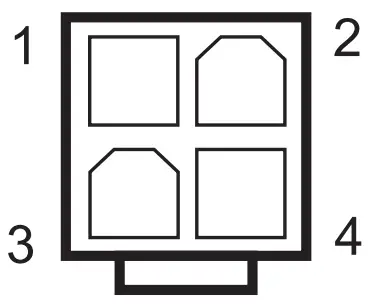
Installation of ROM Socket
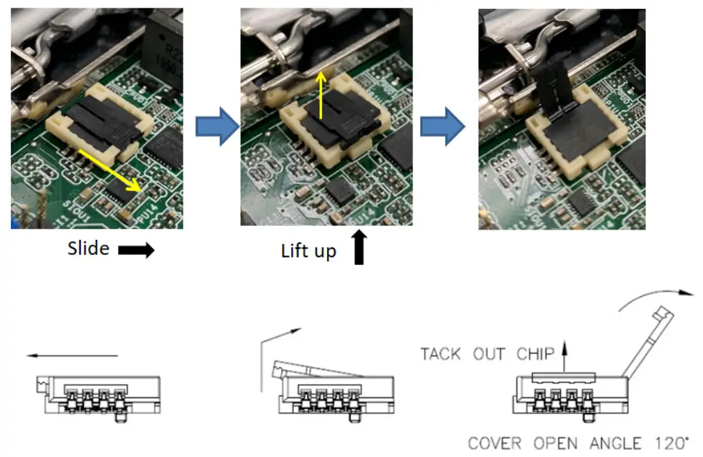
* Do not apply force to the actuator cover after ic inserted.
* Do not apply force to actuator cover when it is opening over 120 degree, Otherwise, the actuator cover may be broken.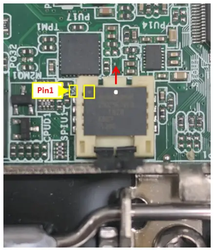 * The yellow dot (Pin1) on the ROM must be installed at pin1 position of the socket (white arrow area).
* Make sure the white dot on the ROM is installed outwards of the socket.
* For further details of how to install ROM, please refer to ASRI website.
Warning: If the installation does not follow as the picture, then it may cause severe damage to chipset & MB.
![]()


