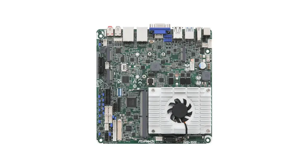
![]() IMB-1006 Intel Processor N97 Mini-ITX Motherboard
IMB-1006 Intel Processor N97 Mini-ITX Motherboard
User Guide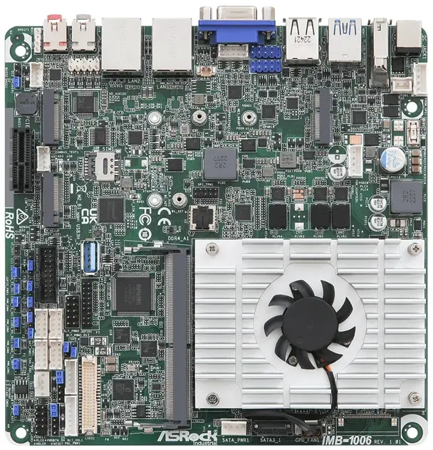
IMB-1006 Intel Processor N97 Mini-ITX Motherboard
The terms HDMI® and HDMI High-Definition Multimedia Interface, and the HDMI logo are trademarks or registered trademarks of HDMI Licensing LLC in the United States and other countries.
Revision History
| Date | Description |
| March 29, 2023 | First Release |
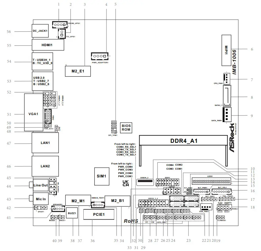
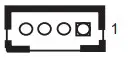
- 4-pin DC-in PWR Connector (Input +12V ~+28V) & UPS Module Power Output Connector
Pin1 and Pin4: GND
Pin2 and Pin3: DC Input
- 2-pin UPS Module Power Input Connector
Pin1: GND
Pin2: DC Input
- M.2 Key-E Socket (M2_E1)
Pin Signal Name Signal Name Pin 1 GND +3.3V 2 3 USB_D+ +3.3V 4 5 USB_D- NA 6 7 GND NA 8 9 NA NA 10 11 NA NA 12 13 NA NA 14 15 NA NA 16 17 NA GND 18 19 NA NA 20 21 NA NA 22 23 NA 33 GND NA 32 35 PETp NA 34 37 PETn NA 36 39 GND NA 38 41 PERp NA 40 43 PERn NA 42 45 GND NA 44 47 PEFCLKp NA 46 49 PEFCLKn NA 48 51 GND NA 53 CLKREQ# PERSTO# 52 55 WAKE# NA 54 57 GND NA 56 59 NA SMB_DATA 58 61 NA SMB_CLK 60 63 GND NA 62 65 NA NA 64 67 NA NA 66 69 GND NA 68 71 NA NA 70 73 NA +3.3V 72 75 GND +3.3V 74 - PWR_ADAPTER1
Pin Signal
NamePin Signal
NamePin Signal
NamePin Signal
Name4 GND 3 5VA 2 5VA_
CONTROL1 GND - SPI_TPM Header (SPI_TPM1)

- MIPI1
- CPU FAN Connector (+12V)

- SATA3 Connector (SATA3_1)
- SATA Power Output Connector

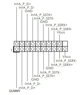
- USB3.2 Gen1 Connector (USB3H_2)
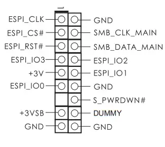
- ESPI Header

- CON_LBKLT_CTL Voltage Level (BLT_PWM2)
1-2: +3V
2-3: +5V
- Brightness Control Mode (BLT_PWM1)
1-2: From eDP PWM to CON_LBKLT_ CTL
2-3: From LVDS PWM to CON_LBKLT_CTL - LVDS Panel Connector
 * eDP pin definition (switch by BIOS):
 - Backlight Power Connector (BLT_PWR1)
Pin Signal
NamePin Signal
Name.
PinSignal
Name.
PinSignal
Name.
PinSignal
Name.
PinSignal
Name6 LCD BLT— VCC 5 LCD BLT— VCC 4 VCC
CON LBKL
EN —3 CON
LBKLI2 CTL
GND
1GND - Backlight Volume Control (BLT_VOL1)

Pin Signal
NamePin Signal
NamePin Signal Name Pin Signal Name Pin Signal
NameD.
1 PinSignal
NamePin Signal
Name7 GND 6 GND 5 BRIGHTNESS—
DW4 BRIGHTNESS—
UP3 PWRDN 2 GPIO
VOL DW1 1
GPIO
VOL UP - 17 : eDP and LVDS Panel Power Select
(LCD_VCC) (PNL_PWR1)
1-2: LCD_VCC: +3V
2-3: LCD_VCC: +5V
4-5: LCD_VCC: +12V
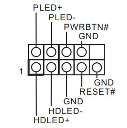
- System Panel Header (PANEL1)


- Clear CMOS Header (CLRMOS1)
1-2 : Normal
2-3 : Clear CMOS - eDP and LVDS Backlight Power Select
(LCD_BLT_VCC) (BKT_PWR1)
1-2: LCD_BLT_VCC: +5V
2-3: LCD_BLT_VCC: +12V
4-5: LCD_BLT_VCC: DC Input - 4-Pin Chassis FAN Connector (+12V)

- USB3.2 Gen1 Connector (USB3H_3_4)


Installation of ROM Socket
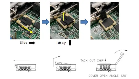
* Do not apply force to the actuator cover after ic inserted.
* Do not apply force to actuator cover when it is opening over 120 degree, Otherwise, the actuator cover may be broken.
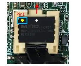
* The yellow dot (Pin1) on the ROM must be installed at pin1 position of the socket.
* Make sure the white dot on the ROM is installed outwards of the socket.
* For further details of how to install ROM, please refer to ASRI website.
Warning: If the installation does not follow as the picture, then it may cause severe damage to chipset & MB.
* Auto clear CMOS when system boot improperly


