
![]()
Safety, Operation & Maintenance
HV18 Hydraulic Power Unit
40404 User Manual 5/2019 Ver. 12
![]() DECLARATION OF CONFORMITY
DECLARATION OF CONFORMITY
I, the undersigned:
Nuerenberg, David
Surname and First names
hereby declare that the equipment specified hereunder:
HV18 Hydraverter Power Unit
- Category: Hydraverter
- Make: STANLEY
- Type: HV18300 / HV18301
- Serial number of equipment: All
Has been manufactured in conformity withDirective/Standards No. Approved body EN ISO
EN ISO3744
13732-1Self
Self - Special Provisions: None
- Representative in the Union: Patrick Vervier, Stanley Dubuis 17-19, rue Jules Berthonneau-BP 3406 41034 Blois Cedex, France.
Done at a STANLEY Infrastructure, Milwaukie, Oregon USA Date 4-28-2018
Signature:
Position: North America Quality Manager
Safety Precautions
| The Safety Alert Symbol alerts you to potential personal injury hazards. Obey all safety messages that follow to avoid possible injury or death. | |
| Indicates an imminently hazardous situation which will result in death or serious injury. | |
| Indicates a potentially hazardous situation which could result in death or serious injury. | |
| Indicates a potentially hazardous situation which could result in property damage. |
Always observe safety symbols. They are included for your safety and for the protection of the tool.![]() WARNING: Read all safety warnings and instructions. Failure to follow warnings and instructions may result in tool damage and/or serious injury.
WARNING: Read all safety warnings and instructions. Failure to follow warnings and instructions may result in tool damage and/or serious injury.
WARNING: To reduce the risk of injury, read the instruction manual.
General
- Do not discard safety instructions. Give to the operator.
- This tool will provide dependable service if operated in accordance with the instructions given in this manual. Read and understand this manual and any stickers and tags attached to the tool and hoses before operation. Failure to do so could result in personal injury or equipment damage.
- Inspect the tool before each use and ensure all decals are legible.
Contact STANLEY if replacements are needed. - Establish a training program for all operators to ensure safe operation.
Do not operate the tool unless thoroughly trained or under the supervision of an instructor. Keep out of the reach of children. - Operators and maintenance personnel shall be able to physically handle the bulk, weight and power of the tool.
- Do not operate a damaged, improperly adjusted, modified or incompletely assembled tool.
- Do not operate the tool in explosive atmospheres, such as in the presence of flammable liquids, gases or dust. Power tools create sparks which may ignite the dust or fumes.
- Provide adequate ventilation in closed areas when operating a gas or diesel hydraulic power source.
- Do not inspect, carry, clean, change accessories or perform maintenance on the tool while the power source is connected.
Accidental engagement of the tool can cause serious injury. - Stay alert, watch what you are doing and use common sense when operating a hydraulic tool. Do not operate this tool if you are tired or under the influence of drugs or alcohol. A moment of inattention while operating hydraulic tools may result in serious injury.
- Assess risks to others around you before operating the tool.
- During operation, do not contact mechanisms, accessories or hardware as they can become very hot; use your Personal Protection Equipment (PPE).
- Use and maintain the tool as stated in this manual. Misuse of this tool is forbidden. Misuse of the tool can cause serious injury. Do not modify
the tool in any way. - Supervising personnel should develop additional precautions relating to the specific work area and local safety regulations.
- Do not overreach. Maintain proper footing and balance at all times when using the tool.
- Slips, trips and falls are major causes of workplace injury. Be observant of hoses lying about the work area, as they can be a tripping hazard.
- Operator must start in a work area without bystanders and must assess the risk to bystanders, including the risk of serious injury or death caused by the tool or accessories dropped from an elevated height.
- Operators must be familiar with all prohibited work areas such as excessive slopes and dangerous terrain conditions.
- Only use clean hydraulic fluid and lubricants that have been recommended by STANLEY.
- Ensure tools are working properly and safely by performing preventative maintenance (PM) procedures.
- Repair and service of this tool must only be performed by an authorized and certified dealer.
- Use only replacement parts recommended by STANLEY.
- Check fastener tightness daily and before each use.
- Never operate the tool if you cannot be sure that underground utilities are not present, such as electrical cables, gas pipes, etc. These can cause a hazard if damaged with the tool.
- The tool is not insulated against coming into contact with electric power. Use hose certified as non-conductive.
- Use only hoses and hose couplings that are rated for a minimum working pressure of 2500 PSI (172 BAR).
- Keep the work area well lit.
- Prevent unintentional starting. Ensure the tool is in the off position before connecting to power source, picking up or carrying the tool.
- In spite of the application of relevant safety regulations and the implementation of safety devices, certain residual risks cannot be avoided. These risks are: pinching risk when operating the tool control valve.
Dust and Fumes
- WARNING: Use of this tool on certain materials could generate dust potentially containing a variety of hazardous substances such as asbestos, silica or lead. Inhalation of dust containing these or other hazardous substances could result in serious injury, cancer or death. Protect yourself and those around you. Research and understand the materials you are cutting. Follow correct safety procedures and comply with all applicable national, state or provisional health and safety regulations relating to them, including, if appropriate arranging for the safe disposal of the materials by a qualified person.
- When dust or fumes are created, control them at the point of emission.
Direct tool exhaust to minimize disturbance of dust. - Operate and maintain the tool as recommended in this manual to minimize dust.
- Use respiratory protection in accordance with employers instruction or as required by occupational health and safety regulations.
- Avoid prolonged contact with dust. Allowing dust to get into your mouth, eyes or lay on the skin may promote absorption of harmful chemicals.
PPE
- Always wear safety equipment such as impact resistant goggles, ear protection, head protection, breathing protection and safety shoes at all times when operating the tool.
- Hands may be exposed to hazards, impacts, cuts, abrasions and heat.
Wear gloves.
• Use PPE that conforms to standards ANSI Z87.1 (Eye and Face Protection), ANSI Z89.1 (Head Protection), ANSI Z41.1 (Foot Protection)
and ANSI S12.6 (S3.19) (Hearing Protection). - Do not wear loose fitting clothing when operating the tool. Loose fitting clothing can get entangled with the tool and cause serious injury.

Sound
- Exposure to high noise levels can cause permanent, disabling hearing loss and other problems, such as tinnitus (ringing, buzzing, whistling or humming in the ears). Use hearing protection in accordance with employer’s instructions and as required by occupational health and safety regulations. Appropriate controls to reduce the risk can include actions such as damping materials to prevent work pieces from “ringing”.
- Use and maintain as recommended in the manual to prevent an unnecessary increase in noise levels.
Vibration
- If you experience numbness, tingling, pain or whitening of the skin in your fingers or hands, stop using the tool. Tell your employer and consult a physician.
- Wear warm clothing when working in cold conditions and keep your hands warm and dry.
- Exposure to vibration can cause disabling damage to the nerves and blood supply of the hands and arms.
- Use and maintain as recommended in the manual to prevent an unnecessary increase in vibration.
- Check the vibration level after each service. If higher than normal, contact your STANLEY dealer.
Hydraulic
- Warning: Hydraulic fluid under pressure could cause skin injection injury. Do not check for leaks with your hands. If you are injured by hydraulic fluid, get medical attention immediately.
- Do not let hydraulic oil get on the skin. Hydraulic oil is hot. Wear Personal Protection Equipment (PPE) at all times.
- If exposed to hydraulic fluid, wash hands immediately.
- Do not exceed the maximum relief valve setting stated on the tool.
- Inspect and clean couplers before use, daily. Replace damaged couplers immediately.
- Hydraulic circuit control valve must be OFF before coupling or uncoupling tools. Failure to do so may damage the couplers and cause overheating of the hydraulic system.
- Ensure the couplers are properly connected and are tight.
- Do not operate the tool at fluid temperatures above 140°F (60°C). Higher temperatures can cause operator discomfort and damage to the tool.
- Do not exceed the rated flow and pressure as stated on the tool. Rapid failure of the internal seals may result.
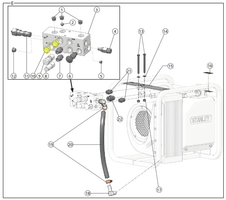
| Manifold Parts Illustration – Detail E | ||
| ITEM | P/N | DESCRIPTION |
| 1 | 350237 | Hex Plug |
| 2 | 18952 | Steel Ball |
| 3 | 40089 | Manifold |
| 4 | 5043 | Relief Valve |
| 5 | 350041 | Hex Plug |
| 6 | 40137 | Tool Circuit Control Valve |
| 7 | 7882 | Adapter |
| 8 | 3976 | Male Coupler |
| 9 | 3975 | Female Coupler |
| 10 | 16800 | Plug |
| 11 | 37301 | Flow Regulator |
| 12 | 350237 | Hex Plug |
| 13 | 27634 | Cap Screw |
| 14 | 4585 | Washer |
| 15 | 40415 | Operation Decal – Model HV18300 |
| 48842 | Operation Decal – Model HV18301 | |
| 16 | 35686 | Hydraulic Fluid Decal |
| 17 | 4353 | Nylock Nut |
| 18 | 40413 | Elbow Adapter |
| 19 | 8045 | Hose Clamp |
| 20 | 4306 | Hose – 19 Inches Long |
| 21 | 350104 | Straight Thread Connector |
| 22 | 2773 | Adapter |
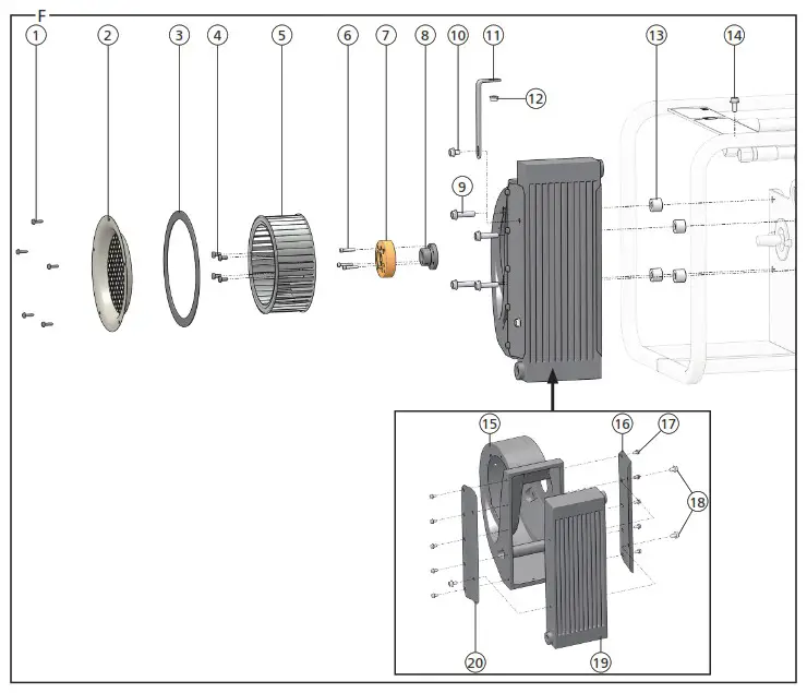
| Fan & Oil Cooler Parts Illustration – Detail F | ||
| ITEM | P/N | DESCRIPTION |
| 1 | 8667 | Screw |
| 2 | 40084 | Inlet Ring |
| 3 | 8669 | Gasket |
| 4 | 27931 | Cap Screw |
| 5 | 8035 | Blower Wheel |
| 6 | 10706 | Cap Screw |
| 7 | 40079 | Blower Hub |
| 8 | 40083 | Bushing |
| 9 | 24142 | Hex Flange Bolt |
| 10 | 40433 | Hex Flange Bolt |
| 11 | 40401 | Angle Bracket |
| 12 | 12787 | Flange Nut |
| 13 | 35782 | Spacer |
| 14 | 40435 | Hex Flange Bolt |
| 15 | 7783 | Blower Housing |
| 16 | 40053 | Cooler Mount |
| 17 | 8668 | Screw |
| 18 | 40433 | Screw |
| 19 | 40078 | Cooler |
| 20 | 40054 | Cooler Mount |
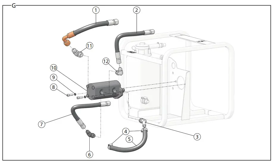
| Motor Parts Illustration – Detail G | ||
| ITEM | P/N | DESCRIPTION |
| 1 | 40407 | Hose Assembly |
| 2 | 40406 | Hose Assembly |
| 3 | 40414 | 45° Elbow Hydraulic Adapter |
| 4 | 8045 | Hose Clamp |
| 5 | 4306 | Hose – 16 Inches Long |
| 6 | 4321 | Straight Thread Elbow Adapter |
| 7 | 40406 | Hose Assembly |
| 8 | 6151 | Cap Screw |
| 9 | 683 | Lock Washer |
| 10 | 40081 | Hydraulic Pump – Model HV18300 |
| 48841 | Hydraulic Pump – Model HV18301 | |
| 11 | 5967 | Straight Thread Elbow Adapter |
| 12 | 4321 | Straight Thread Elbow Adapter |
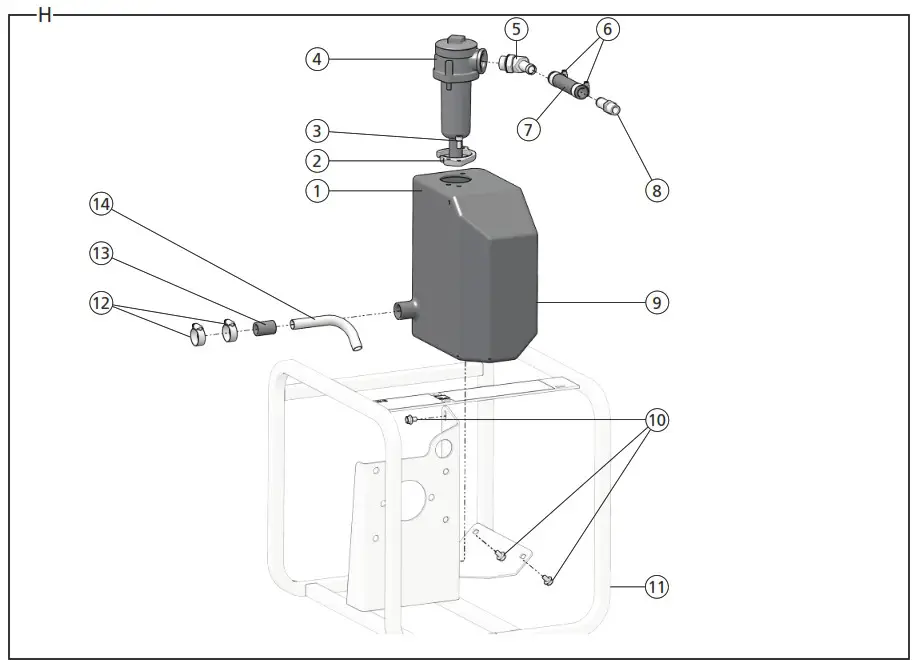
| Hydraulic Oil Reservoir Parts Illustration – Detail H | ||
| ITEM | P/N | DESCRIPTION |
| 1 | 40082 | Hydraulic Oil Tank |
| 2 | 40133 | Grip Plate |
| 3 | 43687 | Cap Screw |
| 4 | 40080 | Filter Assembly |
| 5 | 40364 | 45° Elbow Adapter |
| 6 | 8045 | Hose Clamp |
| 7 | 4306 | Hose – 4 3/4 Inch Long |
| 8 | 40405 | Hose Barb |
| 9 | 40082 | Hydraulic Tank |
| 10 | 40433 | Hex Flange Bolts |
| 11 | 40075 | Frame Weldment |
| 12 | 11179 | Hose Clamp |
| 13 | 7747 | Suction Sleeve |
| 14 | 7749 | Suction Tube |
What is the HV18 Hydraulic Power Unit?
HV18 is a hydraulic power unit that connects to a carrier, such as a backhoe, excavator or skidsteer loader, and uses that carriers main hydraulic circuit to power a self contained 7-9 GPM (27-34 LPM) hydraulic circuit suitable for running hand-held tools. Model HV18300 uses an input supply of 16-35 GPM (61-133 LPM) and model HV18301 uses an input supply of 13-25 GPM (49-95 LPM).
Specifications
| Hydraulic Supply | ||
| Hydraulic Power Source Flow | HV18300 – 16-35 GPM (61-132 LPM) HV18301 – 13-25 GPM (49-95 LPM) | |
| Hydraulic Power Source Supply Relief Pressure | HV18300 – 2000-3000 P51(138-206 BAR) HV18301 – 2300-3000 PSI (159-206 BAR) | |
| Supply Port Size | -12 (3/4) SAE ORB | |
| Hydraulic Output | ||
| Output Flow | 8 GPM (30 LPM) | |
| Output Relief Pressure | 2150 PSI (148 BAR) | |
| Maximum Back Pressure | 400 PSI (28 BAR) | |
| Output Couplers | 3/8 inch Flush Face | |
| Output Port Size | 1/2 inch NPT | |
| Min. Hose Pressure Rating | 2500 PSI (175 BAR) | |
| Max. Hydraulic Oil Temperature | 140°F (60°C) | |
| HTMA/EHTMA Category | Type II, Category D | |
| Tool Weight | 109 lbs. | |
| Tool Size | 21 inches x 19 inches x 18 inches | |
| Sound Declaration | ||
| Measured A-Weighted sound power level | 101.1 dBA | |
| Measured A-Weighted Sound Pressure | 93.1 dBA | |
| Uncertainty, Kpa, in decibels | 1.29 dBA | |
| Values determined according to noise to t code given in ISO 3744. | ||
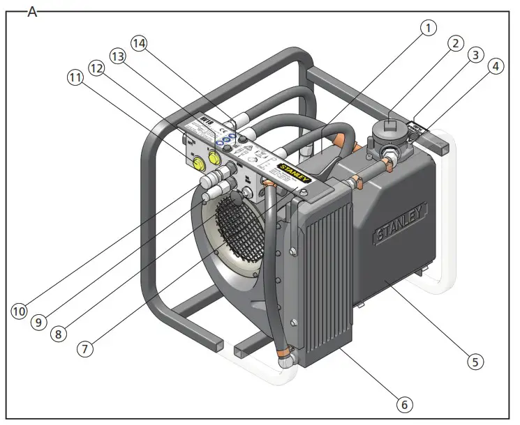
Parts of a HV18 – Detail A
| 1 | Hydraulic Pump |
| 2 | Hydraulic Oil Filter |
| 3 | Hydraulic Fluid Decal |
| 4 | Hydraulic Oil Level Dipstick |
| 5 | Hydraulic Oil Reservoir |
| 6 | Hydraulic Oil Cooler |
| 7 | Operation Decal (includes CE mark & EHTMA Circuit Type “D” Decal) |
| 8 | Tool Circuit Control Valve |
| 9 | Tool Circuit Male Coupler |
| 10 | Tool Circuit Female Coupler |
| 11 | Hydraulic Power Source“Out” Port |
| 12 | Serial Number and Year of Manufacture |
| 13 | Hydraulic Power Source “In” Port |
| 14 | Sound Power Decal |
Tool Setup
![]()
Do not install or perform maintenance while the a hydraulic power source is connected. Accidental engagement of the tool can cause serious injury.
Disconnect and depressurize the hydraulic power source before installing or performing maintenance.
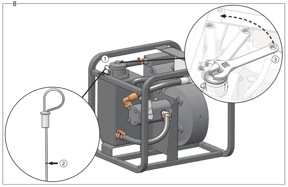
Check and Fill Hydraulic Oil Reservoir – Detail B
- Remove the dipstick from the hydraulic reservoir.
- Ensure the hydraulic oil level is between the max fill line and the bottom of the dipstick.
- If the hydraulic oil level is low, remove the hydraulic oil reservoir cap using a crescent wrench.
- Fill the hydraulic reservoir to the max fill line on the dipstick with an ISO
Grade 32 hydraulic oil.
Note: Use clean hydraulic oil and filling equipment. Only use hydraulic oils recommended by STANLEY. See “STANLEY Recommended Hydraulic Oils” on page 10. - Reinstall the cap before operation.
| STANLEY Recommended Hydraulic Oils | ||
| Brand | Description | Biodegradable? |
| Clarion (CITGO) | Green Bio 32 | Yes |
| Exxon Mobil | EAL 224H | Yes |
| Chevron | Clarity AW32 | Yes |
| Terresolve | Envirologic 132 | Yes |
| Shell | Naturelle HF-E-32 | Yes |
| CITGO | Hydurance AW32 | No |
| AMS Oil | HVH 32 | No |
| Exxon Mobil | DTE 10 Excel | No |
| Shell | S2 V 32 | No |
| Chevron | Rando HDZ 32 | No |
| Conoco Phillips | Unax AW-WR-32 | No |
| Exxon Mobile | Univis HV126 (Recommend for extreme cold) | No |
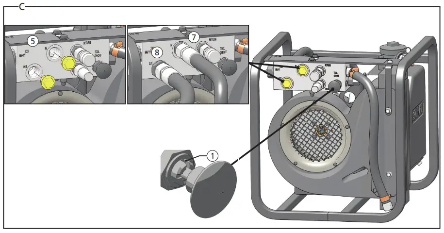
Connect to a Hydraulic Power Source – Detail C
- Ensure the HV18 tool circuit control valve is in the off position.
Note: The off position is when the control valve pegs are in the deepest groove of the valve, pushed all the way in. - Using a calibrated flow and pressure gauge, check the output of the hydraulic power source. Ensure it matches the flow and pressure in “Specifications” on page 10. Hydraulic fluid must be 50°F or above.
Preheat if necessary. - Ensure that the hydraulic power source is equipped with a relief valve set to open at the maximum relief pressure. See “Specifications” on page 10.
- Power down and depressurize the hydraulic power source.
- Remove the plugs from the hydraulic power source ports.
- Wipe the hydraulic power supply hose couplers with a clean, lint free cloth.
- Connect the hydraulic power source pressure hose to the supply “IN” port.
- Connect the hydraulic power source return hose to the supply “OUT” port.
- Ensure the hydraulic power supply couplers are undamaged, properly connected and are tight.
- Power up the hydraulic power source.
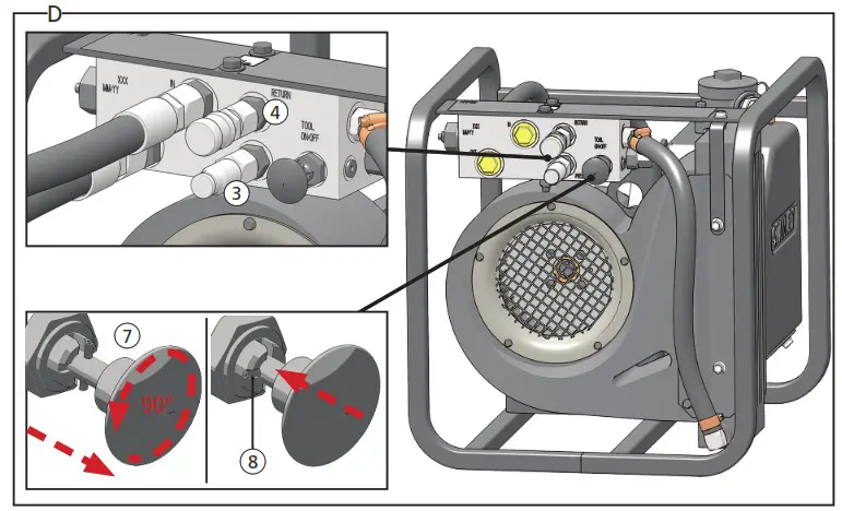
Tool Operation – Detail D
![]()
Use the HV18 as stated in this manual. Misuse of this tool is forbidden. Misuse of the tool can cause serious injury. Do not modify the tool in any way.
- Ensure the tool circuit control valve is in the off position.
Note: The off position is when the control valve pegs are in the deepest groove of the valve, pushed all the way in. - Wipe hose couplers with a clean, lint free cloth.
- Connect the hydraulic tool pressure hose to the male quick coupler marked “Pressure”.
- Connect the hydraulic tool return hose to the female quick coupler marked “Return”.
- Ensure couplers are undamaged, properly connected and are tight.
- Ensure the activation trigger for the hydraulic tool being used is set to the “OFF” position.

Beware of unintentional starting. Serious injury can result. Ensure the tool is in the off position before connecting to power source, picking up or carrying the tool to prevent unintentional starting. - Pull the tool circuit control valve out. Turn the knob 90°.
- Set the valve pegs into the shallow groove of the valve.
- Use the hydraulic tool.
- When finished using the tool, pull the tool circuit control valve out, turn the knob 90° and set the valve pegs into the deepest groove on the valve.
Note: If you encounter a breakdown or the HV18 stops for any reason, set the tool circuit control valve to the “OFF” position, power down and depressurize the hydraulic power source. Disconnect HV18 from the hydraulic power source and plug the supply ports before performing
maintenance.
Tool Maintenance
Daily Maintenance
- Maintain the tool in an area that is clean, free of dirt and debris and is well lit.
- Remove hydraulic power from the tool.
- Throughly clean the fan screen and around the oil cooler.
- Check all hydraulic connections and hoses for damage. Replace damaged parts before operating the tool.
- Using the dipstick, check the hydraulic oil reservoir fill level. Fill if necessary (see “Check and Fill Hydraulic Oil Reservoir – Detail B” on page 10.
- Inspect tool to ensure all decals are legible. Contact STANLEY if replacements are needed.
- Using a calibrated flow and pressure gauge, check the output of the hydraulic power source. Ensure it matches the flow and pressure in “Specifications” on page 10.
Replace the Hydraulic Oil Filter
The hydraulic oil filter must be changed every 200 hours. Change the filter more often if HV18 is operating in a cold, moist or dusty environment.
- Remove hydraulic power from the tool.
- Remove the hydraulic oil reservoir cap using a crescent wrench.
- Pull the filter out of the filter assembly.
- Replace the filter element (part number 40408).
Note: Push the filter down into the filter assembly until you feel it click into place. - Install the cap and lightly tighten with a crescent wrench.
Tool Storage & Transport
Storage
Plug open hydraulic ports. Clean the tool and store in a clean, dry space that is safe from damage.
Transport
Secure the HV18 frame to the transport vehicle. Lift only as high as necessary to load. NEVER lift or transport over people. Ensure HV18 is secured and will not move during transport. An unsecured tool could cause personal injury or damage to the tool.
Tool Disposal
Hydraulic Oil
Hydraulic oil can contaminate the air, ground and water if not properly recycled. Recycle hydraulic oil in accordance with all State, Federal and local laws, at your local oil recycling facility.
Hydraulic Hoses
Hang hydraulic hoses to drain. Collect the oil for recycling. Contact your local municipal recycling authorities for an approved hydraulic hose recycling site.
Tool Body
Drain hydraulic oil from the tool, making sure to collect the oil for recycling.
Disassemble the tool and dispose of all non-metal parts. Recycle the metal components. Contact your local municipal recycling authorities for recycling instructions.
Accessories
| HV18 Accessories | |
| Description | Part Number |
| Supply Hose Kit | 51290 |
| Filter Service Kit | 43592 |
| Filter Element | 40408 |
Troubleshooting
| Problem | Possible Cause | Solution |
| HV18 pump does not run with the hydraulic supply circuit on. | Supply hoses not connected, are obstructed or hydraulic power source is not providing adequate flow and pressure. | Ensure the power source is delivering proper flow and pressure. See “Specifications” on page 10. Check regularly. Ensure supply hoses are properly connected. See “Connect to a Hydraulic Power Source – Detail C” on page 10. |
| Hydraulic power supply relief set too low. | Ensure the hydraulic power supply relief valve is set properly. See “Specifications” on page 10. | |
| HV18 pump has failed. | Contact your STANLEY dealer for service. | |
| HV18 tool hydraulic circuit does not operate tools properly. | Supply hoses not connected, are obstructed or hydraulic power source is not providing adequate flow and pressure. | Ensure the power source is delivering proper flow and pressure. See “Specifications” on page 10. Check regularly. Ensure supply hoses are properly connected. See “Connect to a Hydraulic Power Source – Detail C” on page 10. |
![]()
STANLEY Infrastructure
6430 SE Lake Road, Portland, Oregon 97222 USA
(503) 659-5660 / Fax (503) 652-1780
www.stanleyinfrastructure.com
© 2014 Stanley Black&Decker, Inc.
New Britain, CT 06053 USA


