![]() Cerus X-Drive 3R Standard Variable Frequency Drive
Cerus X-Drive 3R Standard Variable Frequency Drive
User Guide
Safety Information
This equipment should be installed and serviced by technically qualified personnel who are familiar with the correct selection and use of appropriate tools, equipment, and procedures. Failure to comply with national and local electrical and plumbing codes and within Franklin Electric recommendations may result in electrical shock or fire hazard, unsatisfactory performance, or equipment failure.
Read and follow instructions carefully to avoid injury and property damage. Do not disassemble or repair unit unless described in this manual.
Failure to follow installation or operation procedures and all applicable codes may result in the following hazards:
![]() WARNING
WARNING![]() High voltages capable of causing severeinjury or death by electrical shock are present in this unit.
High voltages capable of causing severeinjury or death by electrical shock are present in this unit.
- To reduce risk of electrical shock, disconnect power beforeworking on or around the system. More than one disconnect switch may be required to de-energize the equipment before servicing.
- Serious or fatal electrical shock may result from failure to connect the ground terminal to the motor, drive, metal plumbing, or other metal near the motor or cable, using wire no smaller than motor cable wires.
- Do not remove or install VFD cover for wiring, periodic inspections, or adjustments while power is applied, or the unit is in operation.
- Capacitors inside the drive can still hold lethal voltage even after power has been disconnected—ALLOW 10 MINUTES FOR DANGEROUS INTERNAL VOLTAGE TO DISCHARGE BEFORE REMOVING COVER.
- Operate VFD and control devices with dry hands.
- Do not use VFD if power or motor cable is damaged.
- Do not apply power to a damaged VFD or to VFD with missing parts.
- Perform wiring after VFD has been mounted. Otherwise, electric shock or bodily injury can occur.
This QuickStart Guide includes basic setup and operation information.
For detailed instructions and safety information, please refer to the Cerus X-Drive Installation and Operation Manual www.franklin-controls.com.
![]() CAUTION
CAUTION![]()
![]() Risk of bodily injury, electric shock, or property damage.
Risk of bodily injury, electric shock, or property damage.
- This equipment must not be used by children or persons with reduced physical, sensory or mental abilities, or lacking in experience and expertise, unless supervised or instructed. Children may not use the equipment, nor may they play with the unit or in the immediate vicinity.
- Equipment can start automatically. Lockout-Tagout before servicing equipment.
- This equipment produces high temperatures during normal operation. Use caution when contacting surfaces.
- Do not allow lint, paper, wood chips, dust, metallic chips or other foreign material into the drive.
- Some VFD parameters are set as default to automatically start VFD in some applications. Disable these parameters if automatic start is not safe for personnel or equipment.
NOTICE
Risk of damage to drive or other equipment.
- Take protective measures against ESD (Electrostatic Discharge) before touching control boards during inspection, installation or repair.
- Set correct motor data from the motor nameplate and overload protection parameters for proper motor overload protection.
- Use, if possible, an inverter rated or motor with insulation Class F or higher. For submersible pump motors, use Class B or higher. The VFD generates high frequency output pulses with spikes, which can deteriorate motor winding insulation and eventually damage the motor. The longer distance to the motor the higher amplitude of these voltage spikes will be applied to motor winding. Any cables with paralleled wires will increase the amplitude of these spikes at motor terminals.
- The VFD can operate a motor at frequencies higher than 50HZ or 60Hz. Verify the maximum allowed speed with motor and machinery manufacturers prior to increasing output frequency because it can overheat the motor or damage machinery.
Physical Installation
Environmental Requirements
NOTICE
Risk of damage to VFD, or malfunction can occur due to improper handling, installation, or environment.
- Do not mount VFD on equipment with excessive vibration.
- Install in a location where temperature is within the range of product rating.
- Install VFD on a non-combustible surface. The VFD generates heat during normal operation.
- The VFD should be mounted in a Pollution Degree 2 environment. If VFD will be installed in an environment with a high probability of dust, metallic particles, mists, corrosive gas or other contaminants, the VFD must be mounted inside the appropriate electrical enclosure with proper NEMA, UL or IP rating and adequate cooling.
- When two or more VFDs are installed in a ventilated enclosure, the cooling system should provide adequate airflow for all the VFDs. Do not install VFD above another heat source (another VFD, inductive reactors, etc.).
The VFD must be installed and used in a controlled environment that meets the following requirements:
| Ambient Temperature | 50 °C (122 °F) for UL Open Type/IP20 (top cover must be removed) 40 °C (104 °F) for NEMA 1 / UL Type 1 / IP20 enclosure |
| Location | Pollution Degree 2 Environment |
| Altitude | 1000 m (3281 ft) above sea level. De-rate current 1% per 100 m (328 ft) from 1000 to 2000 m (32816562 ft). Consult Technical Support for installations above 2000 m. |
| Relative Humidity | 95% Maximum relative humidity (non-condensing) |
| Vibration | 1.0 mm, peak to peak value range from 2 Hz to 13.2 Hz 0.7G-1.0G range from 13.2 Hz to 55 Hz 1.0G range from 55 Hz to 512 Hz |
The drive electronics are air-cooled. Provide enough clearance for an airflow around the VFD.
Mount VFD vertically (top up) for proper heat dissipation.
Do not mount VFD in direct sunlight or near other heat sources.
Do not block cooling vents or airflow with any panel components or wires.
See minimum mounting clearance table below for different VFD frame sizes. 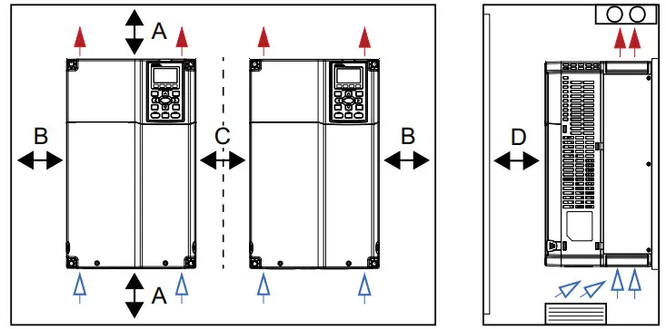
| Frame Size | A | B | C | D |
| A, B, & C | 60 mm/2.4 in. | 30 mm/1.2 in. | 10 mm/0.4 in. | 12 mm/0.5 in. |
| D, E, & F | 100 mm/3.9 in. | 50 mm/2.0 in. | 10 mm/0.4 in. | 25 mm/1.0 in. |
| G | 200 mm/7.9 in. | 100 mm/3.9 in. | 10 mm/0.4 in. | 25 mm/1.0 in. |
| H | 350 mm/ 13.8 in. | 150 mm/6.0 in. | 10 mm/0.4 in. | 50 mm/2.0 in. |
* For frames sizes D, E, & F, install a metal separator between side-by-side drives. Barrier depth must match the VFD depth.
Mounting the Drive
![]() CAUTION
CAUTION
Risk of bodily injury or damage to drive or other equipment.
- The drive should be mounted on a structure such as a wall or post capable of supporting the weight of the unit.
- Install VFD on a non-combustible surface.
- Ensure suitable mounting hardware is used when installing the drive.
- Do not install the drive on unreinforced drywall.
- Use suitable lifting equipment, in good condition, rated for at least 5 times the weight of the drive.
The mounting location should have nearby access to the electrical supply and to the motor wiring.
Use lag screws or bolts appropriate for supporting the weight of the drive.
- Mount the drive using the mounting holes on the back side of the enclosure.
- Screws at the top must attach to a solid structure such as a stud or brace.
- All screw hole locations should be used to ensure the drive is securely mounted.
IMPORTANT: Do not drill holes in the drive.
Electrical Installation
Wiring Guidelines![]() WARNING
WARNING![]() Contact with hazardous voltage could result in death or serious injury.
Contact with hazardous voltage could result in death or serious injury.
- Disconnect and lock out all power before installing or servicing equipment.
- Always check if DC bus charge LED is off and DC voltage on the terminals DC (+1) and DC (-) is less than 30 VDC before working on VFD wiring. The DC bus capacitors may hold high-voltage charge for several minutes after the VFD power is disconnected.
- Connect the motor, the drive, metal plumbing, and all other metal near the motor or cable to the power supply ground terminal using wire no smaller than motor cable wires.
- All wiring must comply with the National Electrical Code and local codes.
NOTICE
Risk of damage to VFD, or malfunction can occur.
Follow all wire routing and grounding instructions carefully. Inductive currents caused by parallel wiring, or close proximity between high voltage and control wiring can cause unexpected behaviors.
- Do not run input power and motor wires in the same conduit.
- Do not run motor wires from multiple VFDs in common conduit.
- Do not run control wiring parallel with high voltage wiring.
- Do not run VFD wiring parallel with building or facility wiring.
- Do not install power factor correction capacitors, surge suppressors, or RFI filters to the VFD output.
- The use of any disconnecting device (contactor, disconnect etc.) in motor circuit during VFD run can cause damage to VFD power components. Stop VFD before opening the motor circuit with disconnect or contactor.
- Do not use aluminum wires for VFD connections.
- Do not leave wire fragments, metal shavings or other metal objects inside the VFD.
- Improper splicing or damage to motor cable insulation may expose the conductor(s) to moisture and can produce tripping on faults or VFD damage.
- For retrofit application, check the integrity of power and motor leads. This requires measuring the insulation resistance with a suitable megohm-meter.
Branch Circuit Protection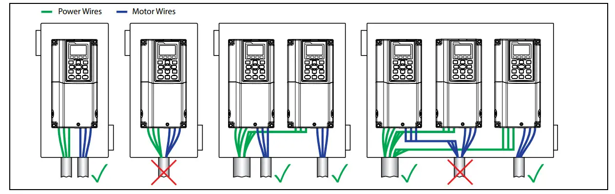
- Mount the drive as close as possible to the service entrance panel. Connect directly to the service entrance, not to a sub-panel.
- Use a dedicated branch circuit for the drive. Verify that the circuit is equipped with a properly-sized circuit breaker or fuse.
- Separate input power and motor wiring by at least 8 in. (20.3 cm).
- Cross over other branch circuits and facility wiring at a 90º angle. If necessary to run wires in parallel, separate by at least 8 in. (20.3 cm).
- All control wiring—sensors, switches, transducers, etc.—should be in a separate conduit routed individually, not parallel, from high voltage wiring. In addition, any shielded cables should be properly grounded.
- Treat Open-Delta power configuration (two-transformer utility bank) as single-phase power and size wiring accordingly.
- Install a line reactor for VFDs in pump systems with dedicated service transformer to protect VFD from transient power surges and provide some degree of harmonics distortion mitigation.
Branch Circuit Protection
Integral solid-state short circuit protection does not provide branch circuit protection. Branch Circuit Protection must be provided in accordance with the National Electrical Code (NEC) and applicable local codes; or equivalent as determined by Authorities Having Jurisdiction (AHJ). The Drive shall be protected by Listed Class J fuses, Listed inverse-time circuit breakers, or Franklin Electric Manual Motor Starters.
Short-circuit current rating (SCCR): The drive is suitable for use on a circuit capable of delivering not more than 100,000 symmetrical amperes (rms) when protected by suitable Class J fuses. Rated fuse current shall be maximum 3 times the motor output fullload current (FLA) rating. Rated circuit breaker current shall be maximum 2.5 times the motor output FLA rating when using single phase or polyphase AC motors. For all other motors, refer to NEC Sec 430 and the Franklin Electric Aim Manual. When protected by a circuit breaker and placed in a panel, drive SCCR is as follows:
| VFD Output Rating | Test Current |
| Up to 50 HP (0 to 37.3 kW) | 5,000 Amperes (rms) |
| 51 to 200 HP (39 to 149 kW) | 10,000 Amperes (rms) |
| 201 to 400 HP (150 to 298 kW) | 18,000 Amperes (rms) |
| 401 to 600 HP (299 to 447 kW) | 30,000 Amperes (rms) |
| 601 to 900 HP (448 to 671 kW) | 42,000 Amperes (rms) |
Wire Sizing
Size power wire to maintain a voltage drop less than 2% at VFD or motor terminals. For submersible pumping applications, refer to the Franklin Electric AIM Manual for wire gauge and distance information.
Frame A: Use only copper conductors rated for at least 75ºC and 600 V. Use cable with a 90ºC rating if ambient environment is greater than 50ºC.
Frame B and above: Use only copper conductors rated for at least 75ºC and 600 V. Use cable with a 90ºC rating if ambient environment is greater than 40ºC (30ºC for models CX-061A-2V, CX-105A-2V, CX-370A-4V, or CX-930A-4V).
460 and 575 V applications: Install a load (output) reactor to protect motor windings if distance from VFD to a motor is in the range 45-100 ft (13.7-30.5 m). Install output dV/dt filter for a range 100-1000 ft (13.7-304.8 m) or a sine wave filter.
Suggested Maximum Motor Cable Lengths for Non-Submersible Applications
- Without output reactor: 13.7 m (45 ft)
- With output reactor: 30.5 m (100 ft)
- With dV/dt filter: 305 m (1000 ft)
Power Wiring Connections
NOTICE
Risk of damage to drive, or malfunction can occur.
- Do not connect input power to VFD output terminals U, V, and W otherwise VFD can be damaged.
- Ensure that the system is properly grounded all the way to the service entrance panel. Improper grounding may result in loss of voltage surge protection and interference filtering.
- Do not connect any wires except dynamic braking resistor to (B1) and (B2) terminals.
- Do not remove the jumper between terminals (+2) and (+1) except for dynamic braking unit or DC link choke, otherwise the VFD can be damaged.
- When using a general GFCI (Ground Fault Circuit Interrupter), select a current sensor with sensitivity of 200mA or above and not less than 0.1-second operation time to avoid nuisance tripping.
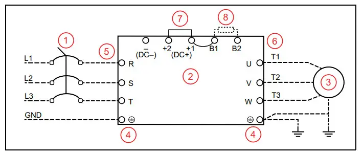
Power Wiring Diagram
- Main Connection, Power
- VFD
- Motor
- Ground Terminals
- Power input terminals
- Output to Motor terminals
- Jumper (optional DC reactor, dynamic brake or DC choke unit)
- Optional brake resistor terminals
 Use ring type terminals for the VFD power wiring.
Power line ground and motor ground wires should be connected to designated ground terminals.
Three-phase power, including Open-Delta must be connected to the R(L1), S(L2), and T(L3) terminals. Proper phase sequencing is not required.
- For single-phase power, connect L1 to R and L2 to S terminals.
- G and H frame VFDs have double-pole power terminals or lugs to accommodate two smaller gauge wires.
Connect three-phase motor wires to the U(T1), V(T2), and W(T3) terminals. When in forward rotation, the motor shaft should turn clockwise when viewed from the motor to the load. If rotation is not correct, reverse any two motor leads.
| Frame | Maximum Terminal Wire Size | Torque |
| Frame A | 8 AWG | 17.4 in-lbs (1.96 Nm) |
| Frame B | 4 AWG | 30.4 in-lbs (3.43 Nm) |
| Frame C | 1/0 AWG | 69.4 in-lbs (7.84 Nm) |
| Frame D0 | 2/0 AWG | 69.4 in-lbs (7.84 Nm) |
| Frame D | 300 MCM or 4/0 AWG | 156 in-lbs (18 Nm) |
| Frame E | 4/0 AWG*2 | 174 in-lbs (20 Nm) |
| Frame F | 300 MCM*2 or 4/0 AWG*2 | 156 in-lbs (18 Nm) |
| Frame G: Terminals R, S, & T | 250 MCM*4 | 156 in-lbs (18 Nm) |
| Frame G: Terminals U, V, & T | 500 MCM*2 | 354 in-lbs (40 Nm) |
| Frame H | 350 MCM*4 | 156 in-lbs (18 Nm) |
Control Circuit Connections
Terminal Identification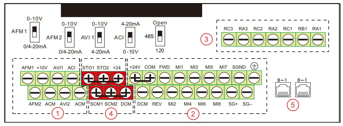
The control board is divided into 5 groups of terminals and connectors, plus a group of micro switches that control individual terminal configurations.
- Always insulate bare control or shield wires with shrink tubing or electrical tape to prevent short circuit.
- The ideal length of stripped wire for control terminals is 5 mm.
1. Analog Inputs/Outputs – These connections are used for transducers, sensors, and control systems such as a BAS, BMS, or PLC. Use shielded cable with shield connected to the ground terminal. Terminals accept 26~16 AWG (0.13~1.3mm ) wires, and should be tightened to a torque of 1.73 lb-in (0.19 Nm).
- ACI is a 0-10 VDC or 4-20 mA input, adjustable by micro switch. Set ACI Input Sel [IO–00] to match the switch setting. Default = 4-20 mA.
- AVI1 is a 0-10 VDC or 4-20 mA input, adjustable by micro switch. Set AVI1 Input Sel [IO–05] to match the switch setting.
Default = 0-10 V. - AVI2 is a 0-10VDC input.
When an input source has been connected, select the appropriate terminal in either Auto Speed Ref [SET–07], Hand Speed Ref [SET–09], or PID F/B Source [SET–18]. - AFM1 & AFM2 are programmable, multi-function analog outputs. Refer to AFMI Out Select [IO–59] and AFM2 Out Select [IO–61] for options. Each output can be set by micro switch to 0-10V (min load 5k Ω at 2 mA) or 0/4-20 mA (max load 500 Ω).
- +10V terminal (with common ACM) provides a +10 VDC 50 mA power supply for input devices.
- ACM terminals are the common for analog inputs, outputs, and +10 VDC power supply. All ACM terminals are connected internally.
IMPORTANT: DCM and ACM terminals are isolated from each other and from the ground. Do not connect these terminals to earth ground, which can cause electrical noise in control circuits and unstable VFD operation.
2. Digital Inputs & RS-485 Communication – These connections provide input for a wide selection of switches or programmable controls. Use shielded cable or twisted wires for 24 VDC digital control circuits wiring and separate these wires from the main power and motor wiring and other high voltage circuits. Terminals accept wire sizes from 26~16 AWG (0.2~1.5mm ), and should be tightened to a torque of 6.9 lb-in (0.78 Nm).
- Digital inputs are configured for NPN (Sink) mode by default, with a jumper across +24 and COM terminals. Refer to the owner’s manual for more details.
- All digital inputs can be re-programmed from Normally Open to Normally Closed.
- Digital inputs are activated by voltage 11 VDC or greater. Maximum input voltage rating is 27 VDC at 3.5 mA.
- MI1-MI8 are programmable, multi-function digital inputs that can be used for a variety of switching features with common terminal DCM. Refer to MI1 Define [IO–21] through MI8 Define [IO–28] for options.
NOTE: MI1 FWD and REV behave as “No Function” - FWD & REV are dedicated Forward and Reverse run commands. If any digital input is programmed for FWD or REV, corresponding dedicated FWD or REV input will be disabled automatically.
- SG+, SG–, & SGND are RS485 communication terminals for PLC, Modbus, or BACnet. Use PLC Com Type [PLC–23] to set the com type. Termination resistance is controlled by micro switch. Set the 485 switch to the Down position to connect 120 Ω termination resistance for long distance or for an electrically noisy environment.
- +24 terminal provides 24 VDC (with DCM common) 50 mA power for digital control circuits and 150 mA for external transducers.
- COM terminal is a digital inputs common. By default, it is connected by jumper to +24 to configure NPN (Sink) mode.
- DCM is the internal 24 VDC power supply common.
 Earth ground. Use this terminal to connect shield wires.
IMPORTANT: DCM and ACM terminals are isolated from each other and from the ground. Do not connect these terminals to earth ground, which can cause electrical noise in control circuits and unstable VFD operation.
3. Relay Outputs – These are configurable, multi-function, dry contact relays. Refer to Relay RA1 [IO–47] through Relay RA3 [IO–49] for options. Terminals accept wire sizes from 26~16 AWG (0.2~1.5mm2), and should be tightened to a torque of 4.3 lb-in (0.49 Nm).
- Relays ratings are 1.25A at 250 VAC, or 3A at 30 VDC.
- RA1-RB1-RC1 is a single-pole, double throw relay. RA1-RC1 is N.O. (normally open), and RB1-RC1 is N.C. (normally closed).
- RA2-RC2 and RA3-RC3 are independent single pole, single throw, normally open relays.
4. Safety Torque Off (STO) Inputs – These connections provide emergency stop control from an external system. By default, the inputs are closed through jumper wires, allowing the drive to run.
5. RJ-45 Sockets – These connections are communication terminals for PLC, Modbus, or BACnet. Use PLC Com Type [PLC–23] to set the Com Type. Then set both Speed Reference and Run Command to RS485. Both RJ-45 sockets and terminals (SG+, SG-, & SGND) are connected internally.
Example Configurations
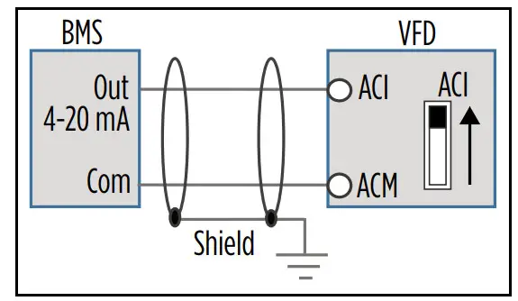
4-20mA Speed Control Signal from an External BMS or PLC:
- Connect the BMS or PLC output signal to the ACI or AVI1 terminal. The ACI micro switch should be in the UP position. If using the AVI1 terminal, the AVI1 micro switch should be DOWN.
- Connect the BMS Com wire to the ACM terminal (signal ground).
- Any shield wire should be connected to Earth ground.
- ACI Input Sel [IO–00] or AVI1 Input Sel [IO–05] should be set to the correct signal type.
- Auto Speed Ref [SET–07] should be set to the chosen input.
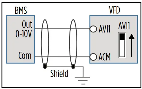
 0-10V Speed Control Signal from an External BMS or PLC:
- Connect the BMS or PLC output signal to the AVI1, AVI2, or ACI terminal. The AVI1 micro switch should be in the UP position. If using the ACI terminal, the ACI micro switch should be DOWN.
- Connect the BMS Com wire to the ACM terminal (signal ground).
- Any shield wire should be connected to Earth ground.
- ACI Input Sel [IO–00] or AVI1 Input Sel [IO–05] should be set to 0-10V.
- Auto Speed Ref [SET–07] should be set to the chosen input.
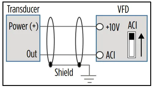
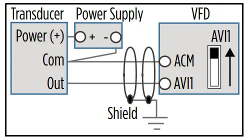
 4-20mA Transducer with VFD 10 VDC Power:
- Connect the transducer positive (Power) wire to the VFD +10V terminal.
- Connect the transducer output (Out) wire to the ACI or AVI1 terminal. The ACI micro switch should be in the UP position. If using the AVI1 terminal, the AVI1 micro switch should be DOWN.
- Any shield wire should be connected to Earth ground.
- ACI Input Sel [IO–00] or AVI1 Input Sel [IO–05] should be set to the correct signal type.
- Auto Speed Ref [SET–07] should be set to PID Output, PID F/B Source [SET–18] should be set to the chosen input, and PID F/B Unit [SET–19] should be set to the appropriate scale (psi, temp, flow, etc.).
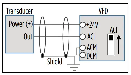
 4-20mA Transducer with VFD 24 VDC Power:
- Connect the transducer positive (Power) wire to the VFD +24V terminal.
- Connect the transducer output (Out) wire to the ACI or AVI1 terminal. The ACI micro switch should be in the UP position. If using the AVI1 terminal, the AVI1 micro switch should be DOWN.
- Use a jumper wire to connect the ACM and DCM terminals.
- Any shield wire should be connected to
 Earth ground.
 - ACI Input Sel [IO–00] or AVI1 Input Sel [IO–05] should be set to the correct signal type.
- Auto Speed Ref [SET–07] should be set to PID Output, PID F/B Source [SET–18] should be set to the chosen input, and PID F/B Unit [SET–19] should be set to the appropriate scale (psi, temp, flow, etc.).

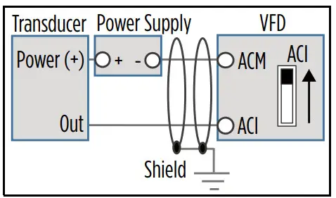
4-20mA Transducer with External 24 VDC Power:
- Connect the transducer positive (Power) wire to the external source positive [+24V]. Connect the external source negative to the VFD ACM terminal.
- Connect the transducer output (Out) wire to the ACI or AVI1 terminal. The ACI micro switch should be in the UP position. If using the AVI1 terminal, the AVI1 micro switch should be DOWN.
- Any shield wire should be connected to Earth ground.
- ACI Input Sel [IO–00] or AVI1 Input Sel [IO–05] should be set to the correct signal type.
- Auto Speed Ref [SET–07] should be set to PID Output, PID F/B Source [SET–18] should be set to the chosen input, and PID F/B Unit [SET–19] should be set to the appropriate scale (psi, temp, flow, etc.).
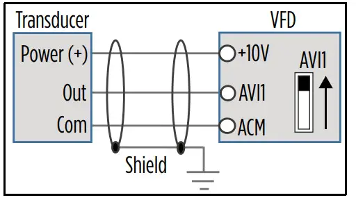
0-10VDC Transducer with VFD 10 VDC Power:
- Connect the transducer positive (Power) wire to the VFD +10V terminal.
- Connect the transducer output (Out) wire to the AVI1, AVI2, or ACI terminal. The AVI1 micro switch should be in the UP position. If using the ACI terminal, the ACI micro switch should be DOWN.
- Connect the transducer Com wire to the ACM terminal (signal ground).
- Any shield wire should be connected to Earth ground.
- ACI Input Sel [IO–00] or AVI1 Input Sel [IO–05] should be set to 0-10V.
- Auto Speed Ref [SET–07] should be set to PID Output, PID F/B Source [SET–18] should be set to the chosen input, and PID F/B Unit [SET–19] should be set to the appropriate scale (psi, temp, flow, etc.).
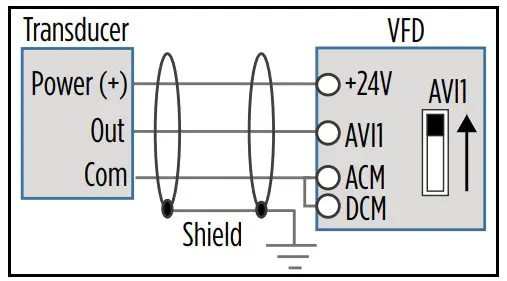
0-10VDC Transducer with VFD 24 VDC Power:
- Connect the transducer positive (Power) wire to the VFD +24V terminal.
- Connect the transducer output (Out) wire to the AVI1, AVI2, or ACI terminal. The AVI1 micro switch should be in the UP position. If using the ACI terminal, the ACI micro switch should be DOWN.
- Connect the transducer Com wire to the ACM terminal (signal ground).
- Use a jumper wire to connect the ACM and DCM terminals.
- Any shield wire should be connected to Earth ground.
- ACI Input Sel [IO–00] or AVI1 Input Sel [IO–05] should be set to 0-10V.
- Auto Speed Ref [SET–07] should be set to PID Output, PID F/B Source [SET–18] should be set to the chosen input, and PID F/B Unit [SET–19] should be set to the appropriate scale (psi, temp, flow, etc.).
0-10VDC Transducer with External 24 VDC Power:
- Connect the transducer positive (Power) wire to the external source positive [+24V].
- Connect the transducer Com wire to the external source negative.
- Connect the transducer output (Out) wire to the AVI1, AVI2, or ACI terminal. The AVI1 micro switch should be in the UP position. If using the ACI terminal, the ACI micro switch should be DOWN.
- Any shield wire should be connected to Earth ground.
- ACI Input Sel [IO–00] or AVI1 Input Sel [IO–05] should be set to 0-10V.
- Auto Speed Ref [SET–07] should be set to PID Output, PID F/B Source [SET–18] should be set to the chosen input, and PID F/B Unit [SET–19] should be set to the appropriate scale (psi, temp, flow, etc.).
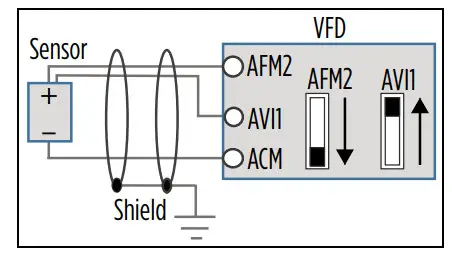
Temperature Protection or PID Control with PT-100 or PTC Sensor:
- Connect the sensor Positive wire to the AFM2 terminal. Place the AFM2 micro switch in the DOWN position.
- Connect the sensor Negative wire to the ACM terminal.
- Use a jumper wire to connect the AFM2 and AVI1 terminals. The AVI1 micro switch should be in the UP position.
- Any shield wire should be connected to Earth ground.
- For PT100, AVI1 Input Sel [IO-05] should be set to PT100 & AFM2.
- If using PT100 for PID Feedback, Spare Sensor, or Aux Sensor, set the max value to 200 °C.
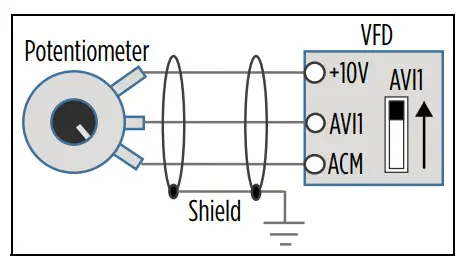
Speed Control using 0-10 VDC Potentiometer:
- Connect the potentiometer Positive wire to the VFD +10V terminal.
- Connect the potentiometer Output wire to the AVI1, AVI2, or ACI terminal. The AVI1 micro switch should be in the UP position. If using the ACI terminal, the ACI micro switch should be DOWN.
- Connect the potentiometer Com wire to the ACM terminal (signal ground).
- Any shield wire should be connected to Earth ground.
- ACI Input Sel [IO–00] or AVI1 Input Sel [IO–05] should be set to 0-10V.
- Auto Speed Ref [SET–07] or Hand Speed Ref [SET–09] should be set to the chosen input.
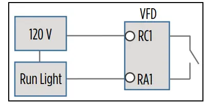
 Relay switching to control an external starter, contactor, or other system:
- Connect the incoming power to the RC terminal.
- Wire the corresponding RA terminal to the external application.
- Set the relay control, Relay RA1, -2, -3 [IO-47, -48, 49].
NOTE: Illustration example uses 120 V, relay 1, and a run light application.
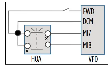
External HOA switch:
- Connect two MI terminals to DCM and the HOA switch.
- Wire a normally open run contact to DCM and FWD terminals.
- MI_ Define [IO-21, -22,…-28] of the two terminals should be set to 1) HOA-HAND, and 2) HOA-AUTO.
- Put HOA Mode Source [SET_60] to Digital Input.
NOTE: Factory-installed drives use MI7 for Hand and MI8 for Auto.
Drive Configuration
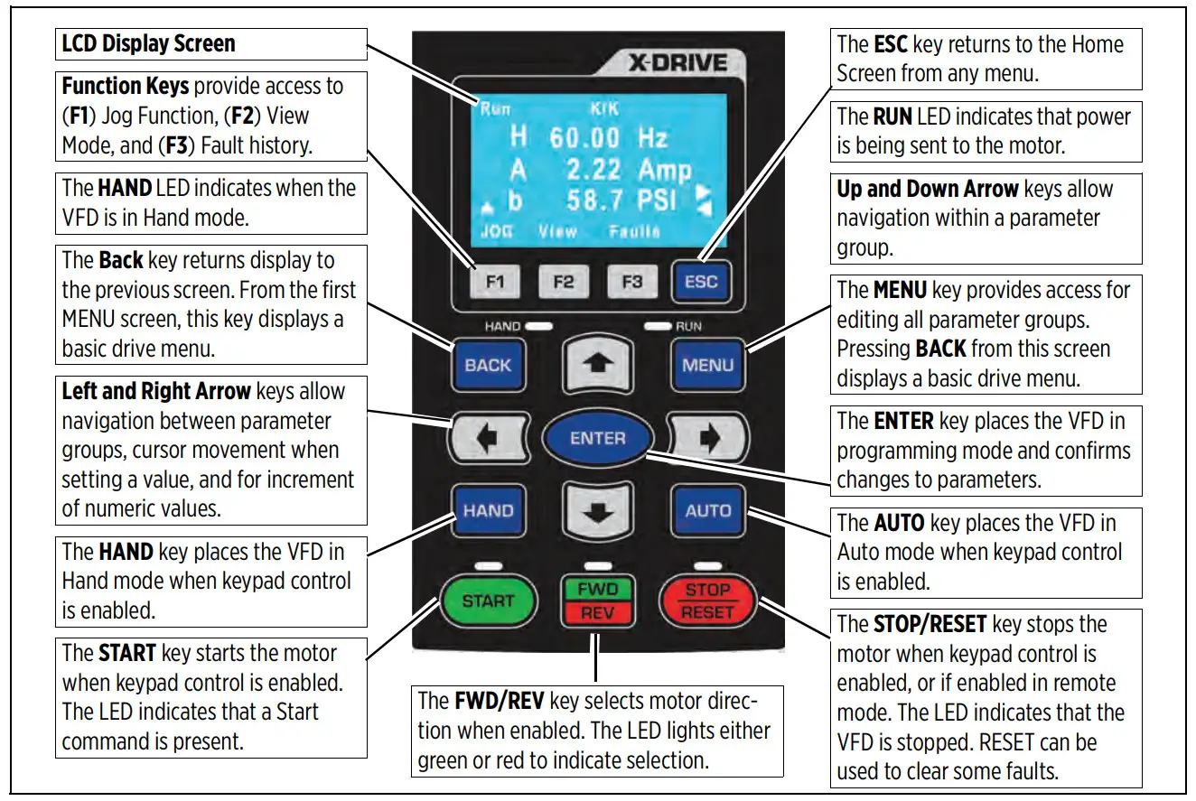
Using the Keypad
Home Screen Display Options
| 1. Operating Status Run/Stop Limit by PID 2 Ctrl by PID 2 Stopped by AI Backspin Timer Lubrication Limit by Level Limit by Temp Stall | 2. Command Source K = Keypad T = Terminal control R = RS485 O = Option board | 3. Frequency Source K = Keypad/PID V1 = from AV1 V2 = from AV2 C = from ACI R = RS485 O = Option board 1-15 = Step speed J = Jog frequency |
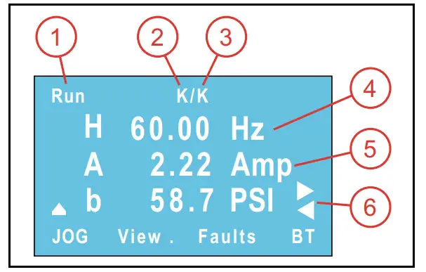
4. Display Line 1 [SET-57] Use Arrow and Enter keys to step through selections and to change setpoints.
H = Output speed when running (Hz).
P = PID Set-point [SET–21] in application based units (PSI, inWC, etc.). This is adjustable using the keypad.
F = Keypad Speed Reference (Hz) when Auto Speed Ref [SET–07] or Hand Speed Ref [SET–09] is set to Keypad. This is adjustable using the keypad.
5. Display Line 2 Displays motor current.
6. Display Line 3 [SET-58] Use Arrow keys to step through choices. This display corresponds to choices in [SET–57].
Enter Required Parameters Before Starting VFD
- Application Sel [SET–00]: Use the keypad to select the type of application the drive will control. When a selection has been made, application related parameters will be automatically updated to proper defaults. Enter the following parameters to ensure best performance for the specific installation.
NOTE: the BASIC application provides standard VFD control with start/stop command from digital inputs and speed reference from a remote analog signal. For systems using a transducer or other control sensors, choose the relevant application type to ensure that correct defaults are set.
NOTE: When using a FE MagForce or other permanent magnet motor application, refer to the owner’s manual. - Input Phase [SET–01]: Verify that the setting matches the type of power supply— 3-phase (default).
- Motor HP [SET–02]: Enter the rated horsepower from the motor nameplate.
- Motor FLA (SFA) [SET–03]: Enter the FLA (Full Load Amps) rating from the motor nameplate, or enter SFA (Service Factor Amps) if using a submersible pump motor.
- Motor RPM [SET–04]: Enter the rated motor RPM from the motor nameplate.
- Motor Voltage [SET–05]: Enter the rated voltage from the motor nameplate.
- Motor Freq Sel [SET-06]: Select the standard motor frequency (either 50 or 60 Hz).
Verify Default Settings
After the initial parameters have been entered, the following default settings should be checked and adjusted to ensure expected operation. Refer to the “Default Settings Tables” on page 16 for a list of automatically populated settings per application.
- VFD Max Freq [VFD–00]: The highest frequency (speed) allowable. If running a FE MagForce pump, this should be set to the calculated electrical frequency corresponding to the target pump RPM. Refer to the Owner’s Manual to set up FE Magforce motors if needed.
- VFD Base Freq [VFD–02]: This should be set to the motor nameplate frequency rating.
- Auto Speed Ref [SET–07]: This is the source of frequency (speed) setpoint the drive will use when in Auto mode.
• When using one of the analog inputs with an automated BAS, BMS, or PLC system, be sure to configure the terminal for the correct signal type. Refer to “Terminal Identification” on page 43.
• When using feedback from a sensor or transducer, select PID Output. When PID mode is selected, additional parameters must be verified for setpoints, inputs, and limits.
• When set to Keypad, the drive will run at the Keypad Speed Reference (F on display). - Auto Run Cmd [SET–08]: The source of RUN command when VFD is in Auto Mode—Keypad or external.
- Hand Speed Ref [SET–09]: The source of frequency (speed) setpoint the drive will use when in Hand mode. PID is disabled in Hand mode. Be sure to configure any selected input terminals for the correct signal type.
• When set to Keypad, the drive will run at the Keypad Speed Reference (F on display). - Hand Run Cmd [SET–10]: The source of RUN command when VFD is in Hand Mode—Keypad or external.
- Accel Time [SET–11]: The time in seconds for drive to ramp up from stop to maximum frequency. Recommended defaults are 2 seconds for submersible pump motors and 20 seconds for most other applications. Additional acceleration curves can be added for more precise control through selected frequency ranges. Refer to “Acceleration/Deceleration Control” on page 82.
- Decel Time [SET–12]: The time in seconds to slow down from maximum frequency to stop. Recommended defaults are 2 seconds for submersibles and 30 seconds for surface/booster pumps. This setting is only effective when Stop Mode [SET–16] is set to Decel to Stop.
Additional deceleration curves can be added for more precise control through selected frequency ranges. Refer to “Acceleration/Deceleration Control” on page 82. - Low Freq Limit [SET–13]: The lowest frequency (speed in Hz) allowed by the VFD in any mode.
- High Freq Limit [SET–14]: The highest frequency (speed in Hz) allowed by the VFD in any mode.
- PID Mode [SET–17]: Enables or disables PID control, either direct or inverse.
- PID F/B Source [SET–18]: The input terminal for PID Feedback source. Be sure to configure the terminal for the correct signal type.
- PID F/B Unit [SET–19]: Selects a measurement unit for PID feedback.
- PID F/B Max [SET–20]: The maximum reading of the feedback source. This is used to scale the analog signal to transducer. For example: if using a 0–200 psi transducer, the value should be 200.
- PID Set-point [SET–21]: The desired value for the drive to maintain in PID mode while running in Auto. This parameter can also be changed through keypad on Line-1 of the display (value P).
- PID Low Hz Limit [SET–22]: Minimum PID frequency output will be limited to this value.
- PID High Hz Limit [SET–23]: Maximum PID frequency output will be limited to this value.
- Language: Select a desired language for the display. Press the Menu button and then press the Back button. Use the Down key to scroll to 5_Set Language.
- Clock: Current time and date. This setting is used to record real-time data for faults, parameter changes, etc. To adjust, press the Menu button and then press the Back button. Use the Down key to scroll to 6_Set Time.
Enter or Verify Optional Settings
There are many optional features available for customizing system operation. Some examples are included in “Example Configurations” on page 7. For more information, refer to the Cerus X-Drive Installation and Operation Manual. Features include:
- Automation features
- Protection features
- Maintenance features
- Communications features
- Multi-Drive/Motor applications
Operation
Basic Operation
The drive can be operated in either HAND or AUTO mode as follows:
- HOA Mode Source [SET–60]: This setting selects whether Hand/Auto control will come from the Keypad, a Digital Input, or Communications.
- HAND mode runs the motor based on Hand Speed Ref [SET–09] (frequency source) and Hand Run Cmd [SET–10] (command source). Defaults for both settings are Keypad, which runs the motor at a fixed speed (Keypad Setpoint) set on the Home Screen. Both settings can be reprogrammed for external control. PID control is disabled in Hand mode.
- AUTO mode runs the motor based on AUTO Speed Ref [SET–07] (frequency source) and AUTO Run Cmd [SET–08] (command source). The speed reference default is set per application. The run command default is Keypad. Both settings can be reprogrammed as required.
Standard Operation with an Automated Control System
In many VFD applications, including ventilation, water supply, or irrigation, motor speed is often determined by an automated system such as a BAS, BMS, or PLC. These systems provide control information to the VFD either through a communications protocol such as Modbus or BACnet, or through direct electrical connection to one of the analog input terminals.
When the drive is in AUTO mode, it runs the motor at a variable frequency based on information from the automation system through the input selected in Auto Speed Ref [SET–07].
Standard Operation with PID Feedback Control
A PID controlled application, such as a fan system or a constant pressure pump system, uses feedback from a transducer to measure system performance against a user defined Setpoint (target) to control motor speed. The VFD can use several types of measurement, including pressure, flow, level, temperature, etc.
For example:
- In a pumping application, the default measurement unit is PSI. As user demand (flow) causes pressure changes, the drive varies the output frequency (motor speed) to maintain pressure at the target setpoint. When the drive determines a no-demand condition, it enters Sleep mode and stops the motor.
- In a fan application, the default measurement unit is inWC (air pressure).
When the drive is in AUTO mode, it runs the motor at a variable frequency based on a comparison between the PID Setpoint [SET–21] and feedback from the PID transducer, up to the PID Hi Hz Limit [SET–23]. PID operation is disabled in HAND mode.
When basic setup is complete, including motor specifications, verify or set the following parameters for PID operation:
Auto Speed Ref [SET–07]: This should be set to PID Output.
Auto Run Command [SET–08]: Select source of Run Command, either Keypad or external. If using a Digital Input (M1-8) with a switch, set the terminal to FWD (or REV) [IO–21 ~ 28].
PID Mode [SET–17]: Set to PID Direct for most PID operations (exceptions are noted in the tables).
Feedback Source [SET–18]: Set to the terminal used for transducer connection. Make sure impedance is set correctly.
PID Feedback Units [SET–19]: Set to the appropriate measurement unit for the transducer type.
PID Feedback Max [SET–20]: Set to the maximum rating of the transducer.
PID Setpoint [SET–21]: Set to the desired measurement target.
PID P-Gain [SET–24]: Proportional Gain controls motor speed adjustments based on the proportional difference between the PID setpoint and PID feedback. Higher settings result in a faster response. However, if the value is too high, it may cause system oscillation and instability. Used along with PID I-TIme [SET-25] to smooth and balance system response.
PID I Time [SET–25]: Integral Time determines PID response time. Lower values increase system response to the feedback signal, which reduces overshoot, but may cause system oscillation if set too low. Greater values provide slower response, which may cause overshoot of the setpoint and oscillation of output frequency.
Sleep Mode [SET–26]: This should be enabled for most pump applications, and Disabled for most HVAC applications.
Sleep Mode with Pressure Boost (Pump Applications)
The Sleep feature monitors pressure and frequency to detect a no-demand condition, at which point it stops the motor. The Sleep Feature also has the option to boost system pressure by a set amount before stopping.
The Sleep feature works only in Auto mode using PID Direct (Sleep is disabled when PID mode is set to Inverse). PID2 operation does not have Sleep function.
The following parameters control Sleep functions:
Sleep Mode [SET–26]: This setting disables or enables sleep mode or the sleep plus boost option. The default value for submersibles and surface/boost pump applications is
Sleep Only. If a pressure boost is desired while the system is at rest, select Sleep + Boost and set a Sleep Boost Value [SET–29].
Sleep Check Time [SET–27]: Time delay (sleep check cycle time) before each Sleep Check procedure. Default = 10 sec.
Sleep Delay [SET–28]: Delay before VFD triggers Sleep Mode when all other conditions are met.
Default = 6sec.
Sleep Boost Value [SET–29]: Value added to original setpoint to provide pressure boost—0.0 to 10.0% of Feedback Max Value [SET–20].
Default = 3%.
Sleep-Boost Timer [SET–30]: Timer that limits sleep boost duration if Sleep Boost setpoint is not reached—5 to 120 seconds.
Default = 10 sec.
Wakeup Level [SET–31]: Sets a wakeup level for VFD to quit Sleep mode and start running—0.0 to [SET-21]. Default = 55 PSI.
Sleep Bump Timer [SET–32]: Sets a duration time for pressure bump to increase system pressure as part of the no-demand calculation.
Default = 5sec.
All default settings related to Sleep mode have been calculated for best system performance for most applications. However, some well conditions may require a slight adjustment.
During system setup it is recommended to test the Sleep feature by closing a main valve to simulate a no-demand condition. The system should be running at normal demand, maintaining pressure setpoint, then flow should be decreased slowly until stopped.
- If the system does not enter Sleep mode, it may be necessary to increase the PID Lo Hz Limit [SET–22] to ensure that system pressure reaches PID Setpoint [SET–21] (plus boost, if enabled).
- If, during normal operation, the system enters Sleep mode, but cycles on and off rapidly as it nears the Setpoint, it may be necessary to slightly lower the PID Lo Hz Limit [SET–22] to prevent Sleep mode problems.
Damper Control (HVAC Applications)
The VFD can provide a relay output to open a damper actuator before starting a fan motor. When enabled, the damper relay output is activated when the system receives a RUN command and the motor will start based on the following configurations:
- With Damper Limit Switch: If any Digital Input [IO–21 through 28] is set to Damper Limit Sw and the VFD receives a RUN command, the damper relay is activated and when the damper limit switch is closed (damper is fully open and DI is activated), the VFD will start the motor.
If the limit switch is not closed within the Damper Time Delay [IO–37], the VFD will trip on Damper Fault. If at any point during run mode damper limit switch is open for more than 2 seconds, the VFD will trip on Damper Fault. VFD will try to restart based on retry number setting [PROT–10]. - Without Damper Limit Switch. If no Digital Input is configured for a damper limit switch and the VFD receives a RUN command, the damper relay is activated and when Damper Time Delay [IO–37] is complete, the VFD will start the motor. There is no damper fault detection because there is no damper limit switch feedback.
NOTE: If any other delay timer is set and the VFD receives a RUN command, the damper relay will start after the first timer expires.
During run mode the damper relay stays activated. When a STOP command is received, the damper relay will be deactivated only in VFD stop state. If stop mode is set to deceleration, the relay will be deactivated after VFD reaches zero speed (0.00Hz).
Set the following parameters to use the Damper Control function:
Damper Mode [IO–36]: This setting enables or disables damper mode.
Damper T-Delay [IO–37]: This setting provides a run time delay without a damper limit switch; or, provides a Damper Fault delay for systems that include a damper limit switch. The delay time should be greater than damper opening time.
Damper Output Terminal [IO–47 through 49]: Connect the damper actuator to one of the Relay Outputs (RA1–3), and set the corresponding parameter to 38_Damper Output. Damper Limit SW Terminal [IO–21 through 28]: If the system includes a damper limit switch, connect the switch to one of the Digital Inputs (MI1–8) and set the corresponding parameter to 34_Damper Limit SW.
Auto Restarts [PROT-10]: The number of times the VFD will try to restart after a fault.
Auto Retry Delay [PROT-11]: The time delay before the VFD attempts to restart after a fault.
Fireman’s Override
Fireman’s Override (FO) provides the ability to force the drive to run exhaust fan to purge smoke from fire in the building by activating FO digital input. This mode is available for Basic and Exhaust fan applications.
In FO mode, if Damper Mode is enabled [IO–36], the damper relay output will be activated, but damper time delay [IO–37] will reduce by half before VFD starts. The VFD will not monitor a Damper Switch, if present, and no damper faults will be available. Set the following parameters to use the FO function:
FO Input Terminal [IO–21 through 28]: Connect the FO switch to one of the Digital Inputs (MI1–8) and set the corresponding parameter to either 32 FO with RUN Cmd or 33_FO w/o RUN Cmd.
FO Enable [IO–29]: Enables FO in either Forward or Reverse.
FO Frequency [IO–30]: Setpoint for non-PID operation during FO.
FO Fault Retry [IO–31]: Number of fault resets allowed during FO.
FO Retry Delay [IO–32]: Delay until restart during FO.
FO Mode & Reset [IO–33]: Sets control method and reset method during FO (PID Off Manual, PID Off Auto, PID On Manual, or PID On Auto).
NOTE: FO Mode overrides all non-critical faults. When FO is activated, the Auto Retry Delay (PROT-11) is ignored and the current fault, Prot-11 Delay timer, and Auto Restart counter will be reset.
FO PID S-Point [IO–34]: Setpoint for PID operation during FO.
FO Bypass [IO–72]: Enables Bypass for FO.
FO Bypass Delay [IO–73]: Time delay between FO becoming active and enabling relay output.
Default Settings Tables
Set Menu
Parameters in highlighted rows are reset when the application is changed [SET–00].
| CODE | Display | Basic | Supply Fan | Exhaust Fan | Cooling Tower | Centrifugal Pump | Submersible Pump | Vacuum Pump | Constant Torque | FE MagForce | PM Motor |
| SET-01 | Input Phase | 3-Phase | 3-Phase | 3-Phase | 3-Phase | 3-Phase | 3-Phase | 3-Phase | 3-Phase | 3-Phase | 3-Phase |
| SET-02 | Motor HP | By VFD Rating | By VFD Rating | By VFD Rating | By VFD Rating | By VFD Rating | By VFD Rating | By VFD Rating | By VFD Rating | By VFD Rating | By VFD Rating |
| SET-03 | Motor FLA (SFA) | By VFD Rating | By VFD Rating | By VFD Rating | By VFD Rating | By VFD Rating | By VFD Rating | By VFD Rating | By VFD Rating | By VFD Rating | By VFD Rating |
| SET-04 | Motor RPM | 1750 | 1750 | 1750 | 1750 | 1750 | 3450 | 1750 | 1750 | 3600 | 3450 |
| SET-05 | Motor Voltage | By VFD Rating | By VFD Rating | By VFD Rating | By VFD Rating | By VFD Rating | By VFD Rating | By VFD Rating | By VFD Rating | By VFD Rating | By VFD Rating |
| SET-06 | Motor Freq Sel * | 60 Hz | 60 Hz | 60 Hz | 60 Hz | 60 Hz | 60 Hz | 60 Hz | 60 Hz | 60 Hz | 60 Hz |
| SET-07 | Auto Speed Ref | ACI Analog | PID Output | PID Output | PID Output | PID Output | PID Output | PID Output | ACI Analog | PID Output | ACI Analog |
| SET-08 | Auto Run Cmd | Digital Input | Keypad | Keypad | Keypad | Keypad | Keypad | Keypad | Keypad | Keypad | Keypad |
| SET-09 | Hand Speed Ref | Keypad | Keypad | Keypad | Keypad | Keypad | Keypad | Keypad | Keypad | Keypad | Keypad |
| SET-10 | Hand Run Cmd | Keypad | Keypad | Keypad | Keypad | Keypad | Keypad | Keypad | Keypad | Keypad | Keypad |
| SET-11 | Accel Time | 20 Sec | 20 Sec | 20 Sec | 20 Sec | 20 Sec | 2 Sec | 20 Sec | 20 Sec | 2 Sec | 20 Sec |
| SET-12 | Decel Time | 30 Sec | 30 Sec | 30 Sec | 30 Sec | 30 Sec | 2 Sec | 30 Sec | 30 Sec | 2 Sec | 30 Sec |
| SET-13 | Low Freq Limit | 20 Hz | 20 Hz | 20 Hz | 20 Hz | 20 Hz | 30 Hz | 20 Hz | 0 Hz | 60 Hz | 40 Hz |
| SET-14 | High Freq Limit | 60 Hz | 60 Hz | 60 Hz | 60 Hz | 60 Hz | 60 Hz | 60 Hz | 60 Hz | 120 Hz | 120 Hz |
| SET-15 | Load Rotation | FWD Only | FWD Only | FWD Only | FWD Only | FWD Only | FWD Only | FWD Only | FWD Only | FWD & REV | FWD Only |
| SET-16 | Stop Mode | Coast | Coast | Coast | Coast | Decel | Coast | Coast | Decel | Coast | Coast |
| SET-17 | PID Mode | Disable | PID Direct | PID Inverse | PID Inverse | PID Direct | PID Direct | PID Direct | PID Direct | PID Direct | PID Direct |
| SET-18 | PID F/B Source | ACI | ACI | ACI | ACI | ACI | ACI | ACI | ACI | ACI | ACI |
| SET-19 | PID F/B Unit | inWC | inWC | inWC | °F | PSI | PSI | inWC | PSI | PSI | inWC |
| SET-20 | PID F/B Max | 1 inWC | 1 inWC | 1 inWC | 150 °F | 100 PSI | 100 PSI | 406.9 inWC | 100 PSI | 100 PSI | 1 inWC |
| SET-21 | PID Set-point | 0.5 inWC | 0.5 inWC | 0.5 inWC | 76 °F | 60 PSI | 60 PSI | 60 inWC | 60 PSI | 60 PSI | 0.5 inWC |
| SET-22 | PID Lo Hz Limit | 20 Hz | 20 Hz | 20 Hz | 20 Hz | 20 Hz | 30 Hz | 20 Hz | 20 Hz | 60 Hz | 40 Hz |
| SET-23 | PID Hi Hz Limit | 60 Hz | 60 Hz | 60 Hz | 60 Hz | 60 Hz | 60 Hz | 60 Hz | 60 Hz | 120 Hz | 120 Hz |
| SET-24 | PID P-Gain | 1% | 1% | 1% | 1% | 2% | 2% | 1% | 1% | 2% | 1% |
| SET-25 | PID I-Time | 1 Sec | 1 Sec | 1 Sec | 1 Sec | 1 Sec | 1 Sec | 1 Sec | 0.5 Sec | 0.5 Sec | 1 Sec |
| SET-26 | Sleep Mode | Disabled | Disabled | Disabled | Disabled | Sleep Only | Sleep Only | Disabled | Disabled | Sleep Only | Disabled |
| SET-27 | Sleep Chk Time | 10 Sec | 10 Sec | 10 Sec | 10 Sec | 10 Sec | 10 Sec | 10 Sec | 10 Sec | 10 Sec | 10 Sec |
| SET-28 | Sleep Delay Time | 6 Sec | 6 Sec | 6 Sec | 6 Sec | 6 Sec | 6 Sec | 6 Sec | 6 Sec | 6 Sec | 6 Sec |
| SET-29 | S-Boost Value | 3% | 3% | 3% | 3% | 3% | 3% | 3% | 3% | 3% | 3% |
| SET-30 | Sleep Boost Timer | 10 Sec | 10 Sec | 10 Sec | 10 Sec | 10 Sec | 10 Sec | 10 Sec | 10 Sec | 10 Sec | 10 Sec |
| SET-31 | Wake-Up Level | 0.45 inWC | 0.5 inWC | 0.5 inWC | 75 °F | 55 PSI | 55 PSI | 55 inWC | 55 PSI | 55 PSI | 0.5 inWC |
| SET-32 | S-Bump Timer | 5 Sec | 5 Sec | 5 Sec | 5 Sec | 5 Sec | 5 Sec | 5 Sec | 5 Sec | 5 Sec | 5 Sec |
| SET-33 | Pipe Fill Timer | 0 Min | 0 Min | 0 Min | 0 Min | 0 Min | 0 Min | 0 Min | 0 Min | 3 Min | 0 Min |
| SET-34 | Pipe Fill Exit Level | 0.4 inWC | 0.4 inWC | 0.4 inWC | 74 °F | 25 PSI | 25 PSI | 25 inWC | 25 PSI | 25 PSI | 0.4 inWC |
| SET-35 | Pipe Fill Freq | 47 Hz | 47 Hz | 47 Hz | 47 Hz | 47 Hz | 47 Hz | 47 Hz | 47 Hz | 95 Hz | 95 Hz |
| SET-36 | Broken Pipe Lvl | 0 inWC | 0 inWC | 0inWC | 0 °F | 15 PSI | 15 PSI | 0 inWC | 0 PSI | 15 PSI | 0.4 inWC |
| SET-37 | Broken Pipe Freq | 59.5 Hz | 59.5 Hz | 59.5 Hz | 59.5 Hz | 59.5 Hz | 59.5 Hz | 59.5 Hz | 59.5 Hz | 114 Hz | 114 Hz |
| SET-38 | Broken Pipe Dly | 180 Sec | 180 Sec | 180 Sec | 180 Sec | 180 Sec | 180 Sec | 180 Sec | 180 Sec | 180 Sec | 180 Sec |
| SET-39 | OverPress Set | Disabled | Disabled | Disabled | Disabled | OP Auto Reset | OP Auto Reset | Disabled | OP Auto Reset | OP Auto Reset | Disabled |
| SET-40 | OverPress Lvl | 1 inWC | 1 inWC | 1 inWC | 80 °F | 80 PSI | 80 PSI | 80 inWC | 80 PSI | 80 PSI | 1 inWC |
| SET-41 | ULD Select | By Current | By Current | By Current | By Current | By Current | By Current | By Current | By Current | By Torque | By Torque |
| SET-42 | ULD Level | 45% | 45% | 45% | 45% | 45% | 70% | 45% | 45% | 60% | 45% |
| SET-43 | ULD Frequency | 30 Hz | 30 Hz | 30 Hz | 30 Hz | 30 Hz | 59 Hz | 30 Hz | 20 Hz | 60 Hz | 40 Hz |
| SET-44 | ULD Delay | 2 Sec | 2 Sec | 2 Sec | 2 Sec | 2 Sec | 2 Sec | 2 Sec | 2 Sec | 2 Sec | 2 Sec |
DEFAULT SETTINGS TABLES
I/O Menu
CODE | Display | Basic | Supply Fan | Exhaust Fan | Cooling Tower | Centrifugal Pump | Submersible Pump | Vacuum Pump | Constant Torque | FE MagForce | PM Motor |
| SET-45 | ULD Recovery T | 0 Min | 0 Min | 0 Min | 0 Min | 30 Min | 30 Min | 0 Min | 0 Min | 30 Min | 0 Min |
| SET-46 | ULD Recover Cnt | Read Only | Read Only | Read Only | Read Only | Read Only | Read Only | Read Only | Read Only | Read Only | Read Only |
| SET-47 | HLD Select | By Current | By Current | By Current | By Current | By Current | By Current | By Current | By Current | By Torque | By Torque |
| SET-48 | HLD Level | 110% | 110% | 110% | 110% | 110% | 110% | 110% | 150% | 110% | 110% |
| SET-49 | HLD Frequency | 20 Hz | 20 Hz | 20 Hz | 20 Hz | 20 Hz | 30 Hz | 20 Hz | 20 Hz | 60 Hz | 40 Hz |
| SET-50 | HLD Delay | 2 Sec | 2 Sec | 2 Sec | 2 Sec | 2 Sec | 2 Sec | 2 Sec | 2 Sec | 5 Sec | 2 Sec |
| SET-51 | HLD Recovery T | 0 Min | 0 Min | 0 Min | 0 Min | 0 Min | 0 Min | 0 Min | 0 Min | 0 Min | 0 Min |
| SET-52 | HLD Recover Cnt | Read Only | Read Only | Read Only | Read Only | Read Only | Read Only | Read Only | Read Only | Read Only | Read Only |
| SET-53 | ACC Change Freq | 0 Hz | 0 Hz | 0 Hz | 0 Hz | 0 Hz | 0 Hz | 0 Hz | 0 Hz | 60 Hz | 0 Hz |
| SET-54 | Second ACC | 60 Sec | 60 Sec | 60 Sec | 60 Sec | 60 Sec | 60 Sec | 60 Sec | 60 Sec | 5 Sec | 60 Sec |
| SET-55 | Second DEC | 60 Sec | 60 Sec | 60 Sec | 60 Sec | 60 Sec | 60 Sec | 60 Sec | 60 Sec | 5 Sec | 60 Sec |
| SET-56 | ACC/DEC Hyster | 0 Hz | 0 Hz | 0 Hz | 0 Hz | 0 Hz | 1 Hz | 0 Hz | 0 Hz | 1 Hz | 0 Hz |
| SET-57 | Display Line 1 | Freq Command | Freq Command | Freq Command | Freq Command | Freq Command | Freq Command | Freq Command | Freq Command | Freq Command | Freq Command |
| SET-58 | Display Line 3 | PID Feedback % | PID Feedback % | PID Feedback % | PID Feedback % | PID Feedback % | PID Feedback % | PID Feedback % | PID Feedback % | PID Feedback % | PID Feedback % |
| SET-59 | Keypad Freq | 60 Hz | 60 Hz | 60 Hz | 60 Hz | 60 Hz | 60 Hz | 60 Hz | 10 Hz | 115 Hz | 115 Hz |
| SET-60 | HOA Mode Source | Keypad | Keypad | Keypad | Keypad | Keypad | Keypad | Keypad | Keypad | Keypad | Keypad |
| SET-61 | KPD STOP as OFF | Disable | Disable | Disable | Disable | Disable | Disable | Disable | Disable | Disable | Disable |
| SET-62 | Carrier Freq | 2 kHz | 2 kHz | 2 kHz | 2 kHz | 2 kHz | 2 kHz | 2 kHz | 2 kHz | 2 kHz | 2 kHz |
| SET-63 | 2/3-Wire Select | 2-Wire Fwd/Rev | 2-Wire Fwd/Rev | 2-Wire Fwd/Rev | 2-Wire Fwd/Rev | 2-Wire Fwd/Rev | 2-Wire Fwd/ Rev | 2-Wire Fwd/Rev | 2-Wire Fwd/Rev | 2-Wire Fwd/Rev | 2-Wire Fwd/Rev |
* If Motor Freq Sel [SET-06] is changed to 50 Hz, all output frequency related parameters are adjusted. Refer to the owner’s manual.
I/O Menu
Parameters in highlighted rows are reset when the application is changed [SET–00].
| CODE | Display | Basic | Supply Fan | Exhaust Fan | Cooling Tower | Centrifugal Pump | Submersible Pump | Vacuum Pump | Constant Torque | FE MagForce | PM Motor |
| IO-00 | ACI Input Sel | 4-20mA | 4-20mA | 4-20mA | 4-20mA | 4-20mA | 4-20mA | 4-20mA | 4-20mA | 4-20mA | 4-20mA |
| IO-01 | ACI Loss Trip | Disable | Stop/Start | Stop/Start | Stop/Start | Trip Stop | Trip Stop | Trip Stop | Stop/Start | Stop/Start | Trip Stop |
| IO-02 | ACI Loss Level | Below Minimum | Below Minimum | Below Minimum | Below Minimum | Below 0.5xMin | Below 0.5xMin | Below Minimum | Below Minimum | Below 0.5xMin | Below 0.5xMin |
| IO-03 | ACI Loss Delay | 1 Sec | 1 Sec | 1 Sec | 1 Sec | 1 Sec | 1 Sec | 1 Sec | 1 Sec | 1 Sec | 1 Sec |
| IO-04 | ACI Filter T | 0.1 Sec | 0.1 Sec | 0.1 Sec | 0.1 Sec | 0.1 Sec | 0.1 Sec | 0.1 Sec | 0.1 Sec | 0.1 Sec | 0.1 Sec |
| IO-05 | AVI1 Input Sel | 0-10V | 0-10V | 0-10V | 0-10V | 0-10V | 0-10V | 0-10V | 0-10V | 0-10V | 0-10V |
| IO-06 | AVI1 Loss Trip | Disable | Disable | Disable | Disable | Disable | Disable | Disable | Disable | Disable | Disable |
| IO-07 | AVI1 Loss Lvl | Below Minimum | Below Minimum | Below Minimum | Below Minimum | Below 0.5xMin | Below 0.5xMin | Below Minimum | Below Minimum | Below 0.5xMin | Below 0.5xMin |
| IO-08 | AVI1 Loss Delay | 1 Sec | 1 Sec | 1 Sec | 1 Sec | 1 Sec | 1 Sec | 1 Sec | 1 Sec | 1 Sec | 1 Sec |
| IO-09 | AVI1 Filter T | 0.2 Sec | 0.2 Sec | 0.2 Sec | 0.2 Sec | 0.2 Sec | 0.2 Sec | 0.2 Sec | 0.2 Sec | 0.2 Sec | 0.2 Sec |
| IO-10 | AVI2 Filter T | 0.2 Sec | 0.2 Sec | 0.2 Sec | 0.2 Sec | 0.2 Sec | 0.2 Sec | 0.2 Sec | 0.2 Sec | 0.2 Sec | 0.2 Sec |
| IO-11 | Spare Max Value | 1 inWC | 1 inWC | 1 inWC | 150 °F | 200 PSI | 200 PSI | 200 inWC | 200 PSI | 200 PSI | 200 inWC |
| IO-12 | Spare AI Select | AVI1 | AVI1 | AVI1 | AVI1 | AVI1 | AVI1 | AVI1 | AVI1 | AVI1 | AVI1 |
| IO-13 | F/B PT Status | Read Only | Read Only | Read Only | Read Only | Read Only | Read Only | Read Only | Read Only | Read Only | Read Only |
| IO-14 | PID Filter Time | 0.5 Sec | 0.5 Sec | 0.5 Sec | 0.5 Sec | 0.5 Sec | 0.5 Sec | 0.5 Sec | 0.5 Sec | 0.5 Sec | 0.5 Sec |
| IO-15 | PID Delay Time | 0 Sec | 0 Sec | 0 Sec | 0 Sec | 0 Sec | 0 Sec | 0 Sec | 0 Sec | 0 Sec | 0 Sec |
| IO-16 | Limit by Level | Disable | Disable | Disable | Disable | Disable | Disable | Disable | Disable | Disable | Disable |
| IO-17 | Max Limit Level | 6 Feet | 0.9 inWC | 0.9 inWC | 140 °F | 50 PSI | 6 Feet | 50 PSI | 50 PSI | 6 Feet | 6 Feet |
| IO-18 | Min Limit Level | 3 Feet | 0.8 inWC | 0.8 inWC | 130 °F | 40 PSI | 3 Feet | 40 PSI | 40 PSI | 3 Feet | 3 Feet |
| IO-19 | Min Freq Limit | 40 Hz | 40 Hz | 40 Hz | 40 Hz | 40 Hz | 40 Hz | 40 Hz | 40 Hz | 80 Hz | 80 Hz |
| IO-20 | DI Filter | 0.005 Sec | 0.005 Sec | 0.005 Sec | 0.005 Sec | 0.005 Sec | 0.005 Sec | 0.005 Sec | 0.005 Sec | 0.005 Sec | 0.005 Sec |
| IO-21 | MI1 Define | Speed-L | None | None | None | None | None | None | None | None | None |
DEFAULT SETTINGS TABLES
I/O Menu
CODE | Display | Basic | Supply Fan | Exhaust Fan | Cooling Tower | Centrifugal Pump | Submersible Pump | Vacuum Pump | Constant Torque | FE MagForce | PM Motor |
| IO-22 | MI2 Define | Speed-M | None | None | None | None | None | None | None | None | None |
| IO-23 | MI3 Define | Speed-H | None | None | None | None | None | None | None | None | None |
| IO-24 | MI4 Define | Fault Reset | Fault Reset | Fault Reset | Fault Reset | Fault Reset | Fault Reset | Fault Reset | Fault Reset | Fault Reset | Fault Reset |
| IO-25 | MI5 Define | E-Stop | E-Stop | E-Stop | E-Stop | E-Stop | E-Stop | E-Stop | E-Stop | E-Stop | E-Stop |
| IO-26 | MI6 Define | XCEL-L | XCEL-L | XCEL-L | XCEL-L | XCEL-L | XCEL-L | XCEL-L | XCEL-L | XCEL-L | XCEL-L |
| IO-27 | MI7 Define | None | None | None | None | None | None | None | None | None | None |
| IO-28 | MI8 Define | None | None | None | None | None | None | None | None | None | None |
| IO-29 | FO Enable | Disable | Disable | Disable | Disable | Disable | Disable | Disable | Disable | Disable | Disable |
| IO-30 | FO Frequency | 60 Hz | 60 Hz | 60 Hz | 60 Hz | 60 Hz | 60 Hz | 60 Hz | 60 Hz | 115 Hz | 115 Hz |
| IO-31 | FO Fault Retry | 10 | 10 | 10 | 10 | 10 | 10 | 10 | 10 | 10 | 10 |
| IO-32 | FO Retry Delay | 60 Sec | 60 Sec | 60 Sec | 60 Sec | 60 Sec | 60 Sec | 60 Sec | 60 Sec | 60 Sec | 60 Sec |
| IO-33 | FO Mode & Reset | PID Off Auto | PID On Auto | PID On Auto | PID On Auto | PID On Auto | PID On Auto | PID On Auto | PID Off Auto | PID On Auto | PID Off Auto |
| IO-34 | FO PID S-Point | 0 inWC | 0 inWC | 0 inWC | 0 °F | 0 PSI | 0 PSI | 0 inWC | 0 PSI | 0 PSI | 0 inWC |
| IO-35 | Ext Trip Mode | Coast | Coast | Coast | Coast | Coast | Coast | Coast | Coast | Coast | Coast |
| IO-36 | Damper Mode | Disable | Enable | Enable | Disable | Disable | Disable | Disable | Disable | Disable | Disable |
| IO-37 | Damper T-Delay | 60 Sec | 60 Sec | 60 Sec | 60 Sec | 60 Sec | 60 Sec | 60 Sec | 60 Sec | 60 Sec | 60 Sec |
| IO-38 | No-Flow Mode | Disable | Disable | Disable | Disable | Disable | Disable | Disable | Disable | Disable | Disable |
| IO-39 | Prime Time | 20 Sec | 20 Sec | 20 Sec | 20 Sec | 20 Sec | 20 Sec | 20 Sec | 20 Sec | 20 Sec | 20 Sec |
| IO-40 | No-Flow Freq | 20 Hz | 20 Hz | 20 Hz | 20 Hz | 20 Hz | 30 Hz | 20 Hz | 20 Hz | 60 Hz | 40 Hz |
| IO-41 | Lube/S-Clean | Disable | Disable | Disable | Disable | Disable | Disable | Disable | Disable | Disable | Disable |
| IO-42 | S-Clean Timer | 60 Min | 60 Min | 60 Min | 60 Min | 60 Min | 60 Min | 60 Min | 60 Min | 60 Min | 60 Min |
| IO-43 | Pre-Lube Timer | 30 Sec | 30 Sec | 30 Sec | 30 Sec | 30 Sec | 30 Sec | 30 Sec | 30 Sec | 30 Sec | 30 Sec |
| IO-44 | Run-Lube Timer | 0 Sec | 0 Sec | 0 Sec | 0 Sec | 0 Sec | 0 Sec | 0 Sec | 0 Sec | 0 Sec | 0 Sec |
| IO-45 | Post-Lube Timer | 0 Sec | 0 Sec | 0 Sec | 0 Sec | 0 Sec | 0 Sec | 0 Sec | 0 Sec | 0 Sec | 0 Sec |
| IO-46 | DI NO/NC | N.O. | N.O. | N.O. | N.O. | N.O. | N.O. | N.O. | N.O. | N.O. | N.O. |
| IO-47 | Relay RA1 | Fault | Fault | Fault | Fault | Fault | Fault | Fault | Fault | Fault | Fault |
| IO-48 | Relay RA2 | Run | Run | Run | Run | Run | Run | Run | Run | Run | Run |
| IO-49 | Relay RA3 | FDT-4 | FDT-4 | FDT-4 | FDT-4 | FDT-4 | FDT-4 | FDT-4 | FDT-4 | FDT-4 | FDT-4 |
| IO-50 | CNT Attained 0 | 0 | 0 | 0 | 0 | 0 | 0 | 0 | 0 | 0 | 0 |
| IO-51 | CNT Attained 1 | 0 | 0 | 0 | 0 | 0 | 0 | 0 | 0 | 0 | 0 |
| IO-52 | FDT-2 Freq | 60 Hz | 60 Hz | 60 Hz | 60 Hz | 60 Hz | 60 Hz | 60 Hz | 60 Hz | 115 Hz | 115 Hz |
| IO-53 | FDT-2 Bandwdth | 2.0 Hz | 2.0 Hz | 2.0 Hz | 2.0 Hz | 2.0 Hz | 2.0 Hz | 2.0 Hz | 2.0 Hz | 2.0 Hz | 2.0 Hz |
| IO-54 | FDT-3 Freq | 60 Hz | 60 Hz | 60 Hz | 60 Hz | 60 Hz | 60 Hz | 60 Hz | 60 Hz | 115 Hz | 115 Hz |
| IO-55 | FDT-3 Bandwdth | 2.0 Hz | 2.0 Hz | 2.0 Hz | 2.0 Hz | 2.0 Hz | 2.0 Hz | 2.0 Hz | 2.0 Hz | 2.0 Hz | 2.0 Hz |
| IO-56 | I Hi/Lo Setting | 0% | 0% | 0% | 0% | 0% | 0% | 0% | 0% | 0% | 0% |
| IO-57 | FDT-4/5 Setting | 3.0 Hz | 3.0 Hz | 3.0 Hz | 3.0 Hz | 3.0 Hz | 3.0 Hz | 3.0 Hz | 3.0 Hz | 3.0 Hz | 3.0 Hz |
| IO-58 | Relay NO/NC | N.O. | N.O. | N.O. | N.O. | N.O. | N.O. | N.O. | N.O. | N.O. | N.O. |
| IO-59 | AFM1 Out Select | Output FREQ | Output FREQ | Output FREQ | Output FREQ | Output FREQ | Output FREQ | Output FREQ | Output FREQ | Output FREQ | Output FREQ |
| IO-60 | AFM1 Gain | 100% | 100% | 100% | 100% | 100% | 100% | 100% | 100% | 100% | 100% |
| IO-61 | AFM2 Out Select | ACI % | ACI % | ACI % | ACI % | ACI % | ACI % | ACI % | ACI % | ACI % | ACI % |
| IO-62 | AFM2 Gain | 100% | 100% | 100% | 100% | 100% | 100% | 100% | 100% | 100% | 100% |
| IO-63 | AFM1 mA Select | 4-20mA | 4-20mA | 4-20mA | 4-20mA | 4-20mA | 4-20mA | 4-20mA | 4-20mA | 4-20mA | 4-20mA |
| IO-64 | AFM2 mA Select | 4-20mA | 4-20mA | 4-20mA | 4-20mA | 4-20mA | 4-20mA | 4-20mA | 4-20mA | 4-20mA | 4-20mA |
| IO-65 | AFM1 Filter Time | 0.01 Sec | 0.01 Sec | 0.01 Sec | 0.01 Sec | 0.01 Sec | 0.01 Sec | 0.01 Sec | 0.01 Sec | 0.01 Sec | 0.01 Sec |
| IO-66 | AFM2 Filter Time | 0.01 Sec | 0.01 Sec | 0.01 Sec | 0.01 Sec | 0.01 Sec | 0.01 Sec | 0.01 Sec | 0.01 Sec | 0.01 Sec | 0.01 Sec |
| IO-72 | FO Bypass | Disable | Disable | Disable | Disable | Disable | Disable | Disable | Disable | Disable | Disable |
| IO-73 | FO Bypass Delay | 0 Sec | 0 Sec | 0 Sec | 0 Sec | 0 Sec | 0 Sec | 0 Sec | 0 Sec | 0 Sec | 0 Sec |
| IO-74 | D-Inputs Status | Read Only | Read Only | Read Only | Read Only | Read Only | Read Only | Read Only | Read Only | Read Only | Read Only |
| IO-75 | D-Relays Status | Read Only | Read Only | Read Only | Read Only | Read Only | Read Only | Read Only | Read Only | Read Only | Read Only |
| IO-76 | AI Loss Freq | 40 Hz | 40 Hz | 40 Hz | 40 Hz | 40 Hz | 40 Hz | 40 Hz | 40 Hz | 80 Hz | 80 Hz |
ADV Menu
Parameters in highlighted rows are reset when the application is changed [SET–00].
CODE | Display | Basic | Supply Fan | Exhaust Fan | Cooling Tower | Centrifugal Pump | Submersible Pump | Vacuum Pump | Constant Torque | FE MagForce | PM Motor |
| ADV-00 | Upper Bound Int | 100% | 100% | 100% | 100% | 100% | 100% | 100% | 100% | 100% | 100% |
| ADV-01 | PID Out Limit | 100% | 100% | 100% | 100% | 100% | 100% | 100% | 100% | 100% | 100% |
| ADV-02 | Password Input | 0 | 0 | 0 | 0 | 0 | 0 | 0 | 0 | 0 | 0 |
| ADV-03 | Parameter Reset | None | None | None | None | None | None | None | None | None | None |
| ADV-05 | Password Lock | Unlocked | Unlocked | Unlocked | Unlocked | Unlocked | Unlocked | Unlocked | Unlocked | Unlocked | Unlocked |
| ADV-06 | Acc/Dec Type | Linear Acc/ Dec | Linear Acc/ Dec | Linear Acc/ Dec | Linear Acc/ Dec | Linear Acc/ Dec | Linear Acc/ Dec | Linear Acc/ Dec | Linear Acc/ Dec | Linear Acc/ Dec | Linear Acc/ Dec |
| ADV-07 | Acc/Dec Format | Unit 0.1 sec | Unit 0.1 sec | Unit 0.1 sec | Unit 0.1 sec | Unit 0.1 sec | Unit 0.1 sec | Unit 0.1 sec | Unit 0.1 sec | Unit 0.1 sec | Unit 0.1 sec |
| ADV-08 | Energy Saving | Disable | Disable | Disable | Disable | Disable | Disable | Disable | Disable | Disable | Disable |
| ADV-09 | E-Saving Gain | 100% | 100% | 100% | 100% | 100% | 100% | 100% | 100% | 100% | 100% |
| ADV-10 | MMC Mode | Disable | Disable | Disable | Disable | Disable | Disable | Disable | Disable | Disable | Disable |
| ADV-11 | Motor Quantity | 1 | 1 | 1 | 1 | 1 | 1 | 1 | 1 | 1 | 1 |
| ADV-12 | Aux Motor Stop Hz | 0 Hz | 0 Hz | 0 Hz | 0 Hz | 0 Hz | 0 Hz | 0 Hz | 0 Hz | 0 Hz | 0 Hz |
| ADV-13 | Alt Run Time | 720 Min | 720 Min | 720 Min | 720 Min | 720 Min | 720 Min | 720 Min | 720 Min | 720 Min | 720 Min |
| ADV-14 | S-Start ON Delay | 1 sec | 1 sec | 1 sec | 1 sec | 1 sec | 1 sec | 1 sec | 1 sec | 1 sec | 1 sec |
| ADV-15 | S-Start Off Delay | 1 Sec | 1 Sec | 1 Sec | 1 Sec | 1 Sec | 1 Sec | 1 Sec | 1 Sec | 1 Sec | 1 Sec |
| ADV-16 | Motor Switch Tmr | 10 Sec | 10 Sec | 10 Sec | 10 Sec | 10 Sec | 10 Sec | 10 Sec | 10 Sec | 10 Sec | 10 Sec |
| ADV-17 | Motor Switch Hz | 60 Hz | 60 Hz | 60 Hz | 60 Hz | 60 Hz | 60 Hz | 60 Hz | 60 Hz | 115 Hz | 115 Mz |
| ADV-18 | Lag Start Freq | 59.5 Hz | 59.5 Hz | 59.5 Hz | 59.5 Hz | 59.5 Hz | 59.5 Hz | 59.5 Hz | 59.5 Hz | 114 Hz | 114 Hz |
| ADV-19 | Lag Start Delay | 10 Sec | 10 Sec | 10 Sec | 10 Sec | 10 Sec | 10 Sec | 10 Sec | 10 Sec | 10 Sec | 10 Sec |
| ADV-20 | Lag Start Level | 2% | 2% | 2% | 2% | 2% | 2% | 2% | 2% | 2% | 2% |
| ADV-21 | Lead Freq Drop | 10 Hz | 10 Hz | 10 Hz | 10 Hz | 10 Hz | 10 Hz | 10 Hz | 10 Hz | 10 Hz | 10 Hz |
| ADV-22 | MMC Decel Time | 2 Sec | 2 Sec | 2 Sec | 2 Sec | 2 Sec | 2 Sec | 2 Sec | 2 Sec | 2 Sec | 2 Sec |
| ADV-23 | Lag Stop Freq | 35 Hz | 35 Hz | 35 Hz | 35 Hz | 35 Hz | 35 Hz | 35 Hz | 35 Hz | 70 Hz | 50 Hz |
| ADV-24 | Lag Stop Delay | 4 Sec | 4 Sec | 4 Sec | 4 Sec | 4 Sec | 4 Sec | 4 Sec | 4 Sec | 4 Sec | 4 Sec |
| ADV-25 | Lag Stop Level | 0.3% | 0.3% | 0.3% | 0.3% | 0.3% | 0.3% | 0.3% | 0.3% | 0.3% | 0.3% |
| ADV-26 | Lead Freq Bump | 0.0 Hz | 0.0 Hz | 0.0 Hz | 0.0 Hz | 0.0 Hz | 0.0 Hz | 0.0 Hz | 0.0 Hz | 0.0 Hz | 0.0 Hz |
| ADV-27 | MMC Accel Time | 2 Sec | 2 Sec | 2 Sec | 2 Sec | 2 Sec | 2 Sec | 2 Sec | 2 Sec | 2 Sec | 2 Sec |
| ADV-28 | Power-On Delay | 10 Sec | 10 Sec | 10 Sec | 10 Sec | 10 Sec | 10 Sec | 10 Sec | 10 Sec | 10 Sec | 10 Sec |
| ADV-29 | Run Delay Timer | 0 Sec | 0 Sec | 0 Sec | 0 Sec | 0 Sec | 0 Sec | 0 Sec | 0 Sec | 0 Sec | 0 Sec |
| ADV-30 | Backspin Timer | 0 Sec | 0 Sec | 0 Sec | 0 Sec | 0 Sec | 0 Sec | 0 Sec | 0 Sec | 0 Sec | 0 Sec |
| ADV-31 | Aux Timer Type | On-Delay | On-Delay | On-Delay | On-Delay | On-Delay | On-Delay | On-Delay | On-Delay | On-Delay | On-Delay |
| ADV-32 | Aux Timer Time | 10 Sec | 10 Sec | 10 Sec | 10 Sec | 10 Sec | 10 Sec | 10 Sec | 10 Sec | 10 Sec | 10 Sec |
| ADV-33 | Aux Timer Input | FWD DI | FWD DI | FWD DI | FWD DI | FWD DI | FWD DI | FWD DI | FWD DI | FWD DI | FWD DI |
| ADV-34 | Min Run Timer | 0 Sec | 0 Sec | 0 Sec | 0 Sec | 0 Sec | 0 Sec | 0 Sec | 0 Sec | 0 Sec | 0 Sec |
| ADV-35 | Multi-VFD Set | Single VFD | Single VFD | Single VFD | Single VFD | Single VFD | Single VFD | Single VFD | Single VFD | Single VFD | Single VFD |
| ADV-36 | Standby Pumps | 0 | 0 | 0 | 0 | 0 | 0 | 0 | 0 | 0 | 0 |
| ADV-37 | Multi-VFD ID | VFD-1 | VFD-1 | VFD-1 | VFD-1 | VFD-1 | VFD-1 | VFD-1 | VFD-1 | VFD-1 | VFD-1 |
| ADV-38 | VLag Start Freq | 59.5 Hz | 59.5 Hz | 59.5 Hz | 59.5 Hz | 59.5 Hz | 59.5 Hz | 59.5 Hz | 59.5 Hz | 114 Hz | 114 Hz |
| ADV-39 | VLag Start Delay | 10 Sec | 10 Sec | 10 Sec | 10 Sec | 10 Sec | 10 Sec | 10 Sec | 10 Sec | 10 Sec | 10 Sec |
| ADV-40 | VLag Stop Freq | 35 Hz | 35 Hz | 35 Hz | 35 Hz | 35 Hz | 35 Hz | 35 Hz | 35 Hz | 70 Hz | 50 Hz |
| ADV-41 | VLag Stop Delay | 5 Sec | 5 Sec | 5 Sec | 5 Sec | 5 Sec | 5 Sec | 5 Sec | 5 Sec | 5 Sec | 5 Sec |
| ADV-42 | VLead/Lag ID | Read Only | Read Only | Read Only | Read Only | Read Only | Read Only | Read Only | Read Only | Read Only | Read Only |
| ADV-43 | VLag Spd Source | PID | PID | PID | PID | PID | PID | PID | PID | PID | PID |
| ADV-44 | VLag Set Freq | 55 Hz | 55 Hz | 55 Hz | 55 Hz | 55 Hz | 55 Hz | 55 Hz | 55 Hz | 110 Hz | 110 Hz |
| ADV-45 | Alternation | Disable | Disable | Disable | Disable | Disable | Disable | Disable | Disable | Disable | Disable |
| ADV-46 | Alternate TMR | 24 Hour | 24 Hour | 24 Hour | 24 Hour | 24 Hour | 24 Hour | 24 Hour | 24 Hour | 24 Hour | 24 Hour |
| ADV-47 | Set VFD Ready | Ready | Ready | Ready | Ready | Ready | Ready | Ready | Ready | Ready | Ready |
| ADV-48 | Jockey Mode | Disable | Disable | Disable | Disable | Disable | Disable | Disable | Disable | Disable | Disable |
| ADV-49 | J-Start Press | 0.5 inWC | 0.5 inWC | 0.5 inWC | 75 °F | 54 PSI | 54 PSI | 54 inWC | 54 PSI | 54 PSI | 0.5 inWC |
| ADV-50 | J-Start Freq | 50 Hz | 50 Hz | 50 Hz | 50 Hz | 50 Hz | 50 Hz | 50 Hz | 50 Hz | 100 Hz | 100 Hz |
| ADV-51 | Main Stop Freq | 40 Hz | 40 Hz | 40 Hz | 40 Hz | 40 Hz | 40 Hz | 40 Hz | 40 Hz | 80 Hz | 80 Hz |
| ADV-52 | J-Start Delay | 20 Sec | 20 Sec | 20 Sec | 20 Sec | 20 Sec | 20 Sec | 20 Sec | 20 Sec | 20 Sec | 20 Sec |
DEFAULT SETTINGS TABLES
ADV Menu
| CODE | Display | Basic | Supply Fan | Exhaust Fan | Cooling Tower | Centrifugal Pump | Submersible Pump | Vacuum Pump | Constant Torque | FE MagForce | PM Motor |
| ADV-53 | Main Stop Delay | 5 Sec | 5 Sec | 5 Sec | 5 Sec | 5 Sec | 5 Sec | 5 Sec | 5 Sec | 5 Sec | 5 Sec |
| ADV-55 | AVR Select | Enable | Enable | Enable | Enable | Enable | Enable | Enable | Enable | Enable | Enable |
| ADV-56 | Prog-1 Setting | None | None | None | None | None | None | None | None | None | None |
| ADV-57 | Prog-1 On Time | 00:01 | 00:01 | 00:01 | 00:01 | 00:01 | 00:01 | 00:01 | 00:01 | 00:01 | 00:01 |
| ADV-58 | Prog-1 Off Time | 00:01 | 00:01 | 00:01 | 00:01 | 00:01 | 00:01 | 00:01 | 00:01 | 00:01 | 00:01 |
| ADV-59 | Prog-1 Week Day | None Selected | None Selected | None Selected | None Selected | None Selected | None Selected | None Selected | None Selected | None Selected | None Selected |
| ADV-60 | Prog-2 Setting | None | None | None | None | None | None | None | None | None | None |
| ADV-61 | Prog-2 On Time | 00:01 | 00:01 | 00:01 | 00:01 | 00:01 | 00:01 | 00:01 | 00:01 | 00:01 | 00:01 |
| ADV-62 | Prog-2 Off Time | 00:01 | 00:01 | 00:01 | 00:01 | 00:01 | 00:01 | 00:01 | 00:01 | 00:01 | 00:01 |
| ADV-63 | Prog-2 Week Day | None Selected | None Selected | None Selected | None Selected | None Selected | None Selected | None Selected | None Selected | None Selected | None Selected |
| ADV-64 | Prog-3 Setting | None | None | None | None | None | None | None | None | None | None |
| ADV-65 | Prog-3 On Time | 00:01 | 00:01 | 00:01 | 00:01 | 00:01 | 00:01 | 00:01 | 00:01 | 00:01 | 00:01 |
| ADV-66 | Prog-3 Off Time | 00:01 | 00:01 | 00:01 | 00:01 | 00:01 | 00:01 | 00:01 | 00:01 | 00:01 | 00:01 |
| ADV-67 | Prog-3 Week Day | None Selected | None Selected | None Selected | None Selected | None Selected | None Selected | None Selected | None Selected | None Selected | None Selected |
| ADV-68 | Prog-4 Setting | None | None | None | None | None | None | None | None | None | None |
| ADV-69 | Prog-4 On Time | 00:01 | 00:01 | 00:01 | 00:01 | 00:01 | 00:01 | 00:01 | 00:01 | 00:01 | 00:01 |
| ADV-70 | Prog-4 Off Time | 00:01 | 00:01 | 00:01 | 00:01 | 00:01 | 00:01 | 00:01 | 00:01 | 00:01 | 00:01 |
| ADV-71 | Prog-4 Week Day | None Selected | None Selected | None Selected | None Selected | None Selected | None Selected | None Selected | None Selected | None Selected | None Selected |
| ADV-74 | Set-Point-A | 0.5 inWC | 0.5 inWC | 0.5 inWC | 76 °F | 60 PSI | 60 PSI | 60 inWC | 60 PSI | 60 PSI | 0.5 inWC |
| ADV-75 | Set-Point-B | 0.5 inWC | 0.5 inWC | 0.5 inWC | 76 °F | 60 PSI | 60 PSI | 60 inWC | 60 PSI | 60 PSI | 0.5 inWC |
| ADV-76 | Set-Point-AB | 0.5 inWC | 0.5 inWC | 0.5 inWC | 76 °F | 60 PSI | 60 PSI | 60 inWC | 60 PSI | 60 PSI | 0.5 inWC |
For technical assistance, parts, or repair, please contact:
800.348.2420 | franklin-electric.com
Form 10000005066 Rev. 002 03/22![]() Copyright © 2022, Franklin Electric, Co., Inc. All rights reserved.
Copyright © 2022, Franklin Electric, Co., Inc. All rights reserved.


