
Danfoss AME Series Electric Drive
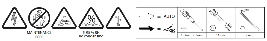
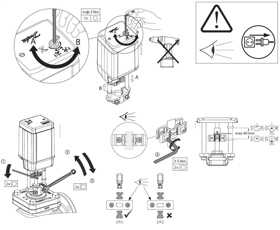
tools
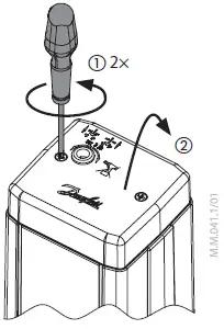
instalation

Wiring for modulating mode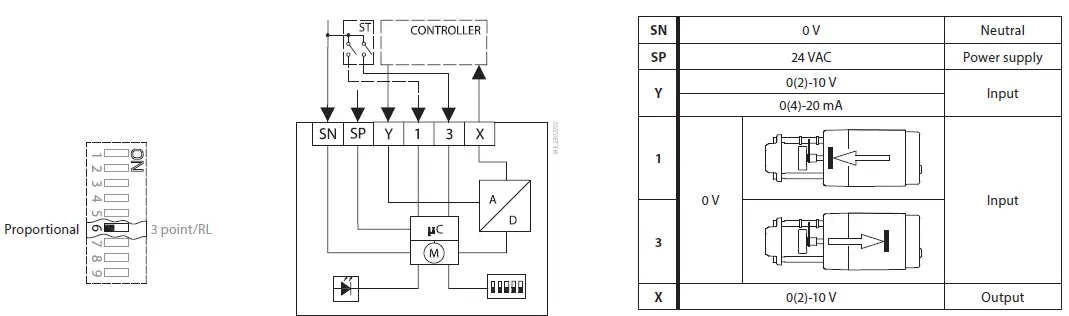 Wiring for 3-point floating mode Controller with relay output
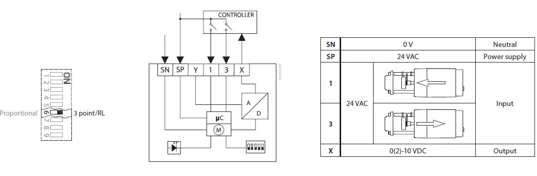 Wiring for 3-point floating mode Controller with triacs output
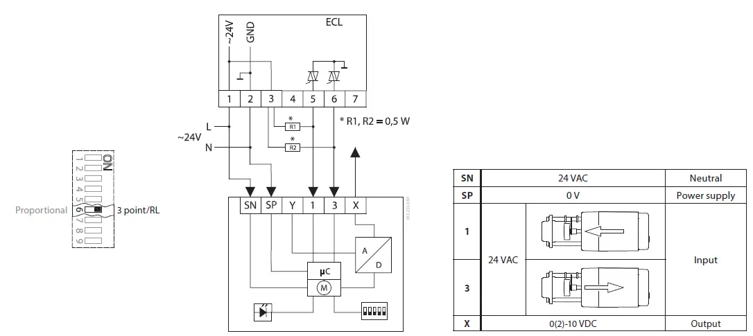
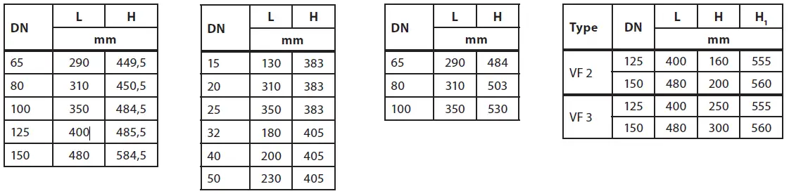
| Type | DN | L | H | H1 |
| mm | ||||
| VF 3 | 65 | 290 | 120 | 428 |
| 80 | 310 | 155 | 444 | |
| VL 3 | 65 | 290 | 120 | 428 |
| 80 | 310 | 155 | 432 | |
| Type | DN | L | H | H1 | H2 |
| mm | |||||
| VF 2 | 100 | 350 | 175 | 406 | 196 |
| VF 3 | |||||
| VL 2 | 100 | 350 | 175 | 406 | 196 |
| VL 3 | |||||
| Type | DN | L | H | H1 | H2 |
| mm | |||||
| VF 2 | 100 | 350 | 175 | 406 | 196 |
| VF 3 | |||||
| VL 2 | 100 | 350 | 175 | 406 | 196 |
| VL 3 | |||||
| DN | L | H | H1 |
| mm | |||
| 40 | 200 | 390 | 645 |
| 50 | 230 | 390 | 645 |
| DN | L | H | H1 |
| mm | |||
| 65 | 290 | 425 | 604 |
| 80 | 310 | 425 | 624 |
| 100 | 350 | 530 | 634 |
| 125 | 400 | 530 | 664 |
Safety Note
To avoid injury of persons and damages to the device, it is absolutely necessary to read and observe these instructions carefully. Necessary assembly, start-up, and maintenance work must be performed by qualified and authorized personnel only.
Prior to assembly and depressurizing the system. Please comply with the instructions of the system manufacturer or system operator
Do not remove the cover before the power supply is fully switched off.
Mounting
Fix the actuator on the valve ❷
Wiring
Do not touch anything on the PCB! Switch off the power line before wire the actuator! Lethal voltage! Wire the actuator according to the wiring diagram.
Control signal
Control signal from the controller must be connected to terminals Y (input signal) and SN (common) on the AME printed board.
Output signal
Output signal from the terminal X can be used for indication of the current position. Range depends on the DIP switch settings.
Supply voltage
Supply voltage (24 V~ -15 to +10%, 50 Hz) must be connected to the terminals SN and SP.
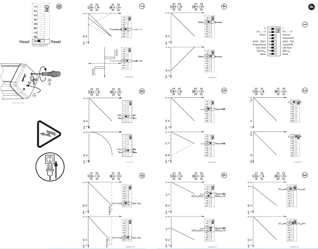
DIP switch settings
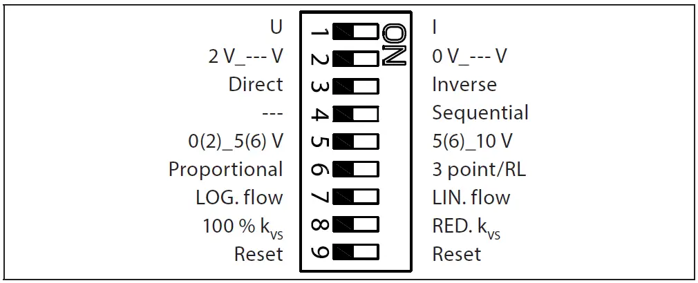
Factory settings:
ALL switches are on OFF position! ①
Note: All combinations of DIP switches are allowed. All functions that are selected are added consecutively. There is only one logic override of functionalities i.e. the switch No.6 Proportional/3 point, which sets actuator to ignore control signal and works as a “simple” 3-point actuator.
SW1: U/I ②
Factory setting: voltage control signal (0-10 V).
SW2: 2-10 V/0-10 V ③
Factory setting is: 2-10 V.
SW3: Direct/Inverse ④
Factory setting is: DIRECT
SW4:—/Sequential ⑤
Two actuators can be set to work parallel with one control signal. If the SEQUENTIAL is set than an actuator responds to split control signal (see 0(2)-5(6) V/5(6)-10 V).
Note: This combination works in combination with switch No. 5: 0(2)-5(6) V/5(6)-10 V
SW5: 0(2)-5(6) V/5(6)-10 V ⑥
Note: This function is available if switch No. 4: — / Sequential is set.
SW6: Proportional/3 point ⑦
Actuator needs to perform Self stroking prior changing DIP 6 to ON. Output signal depends on DIP 2, 3&5 setting.
Actuator can operate in modulating (DIP 6 to OFF) or in “simple” 3-point mode, if the 3-point function is selected (DIP 6 to ON).
Connect power supply on terminals SN and SP terminals.
DIP 6 factory setting is OFF for modulating operation. Actuator’s stem will run to its totally extended or retracted position by bridging SN signal to terminals 1 or 3 and will remain in this position as long as potential is present.
Set DIP 6 to ON for operating actuator in 3 point mode.
Look carefully wiring diagram as wiring is different for controllers with triac output (ECL) in comparison to controllers with relay output
Note: If 3 point function is selected actuator does not respond to any control signal on port Y. It only rises and lowers spindle if power is supplied on port 1 or 3.
SW7: LOG. flow/LIN. flow ⑧
Factory setting is: LOG. Flow (characteristic of valve is unchanged)
Note:
If this function is used in combination with non-logarithmic valves the characteristic of motorised valve will be anti-logarithm of valve’s characteristic (e.g. valve with linear characteristic will be transformed to quick open characteristic).
SW8: 100% KVS/RED. KVS ⑨
Note: This function works proper only with logarithmic (equal percentage) valves.
SW9: Reset ⑩
After the actuator has been connected to power supply, the actuator will start the self-adjustment procedure. The indicator LED flashes until self adjustment is finished. The duration depends on the spindle travel and will normally last a few minutes. The stroke length of the valve is stored in the memory after self adjustment has been completed. To restart self adjustment, change the position of RESET switch (switch No. 9). If the supply voltage is switched off or falls below 80 % in more than 0.1 s, the current valve position will be stored in the memory and all data remain saved in the memory also after a power supply cut-out.
Function test
The indicator light shows whether the positioner is in operation or not. Moreover, the indicator shows the control status and faults.
Constant light
normal operation
No light
no operation or no power supply
Intermittent light (1 Hz)
self adjusting-mode
Intermittent light (3 Hz):
- power supply too low
- insufficient valve stroke (<20 s)
- end-position cannot be reached
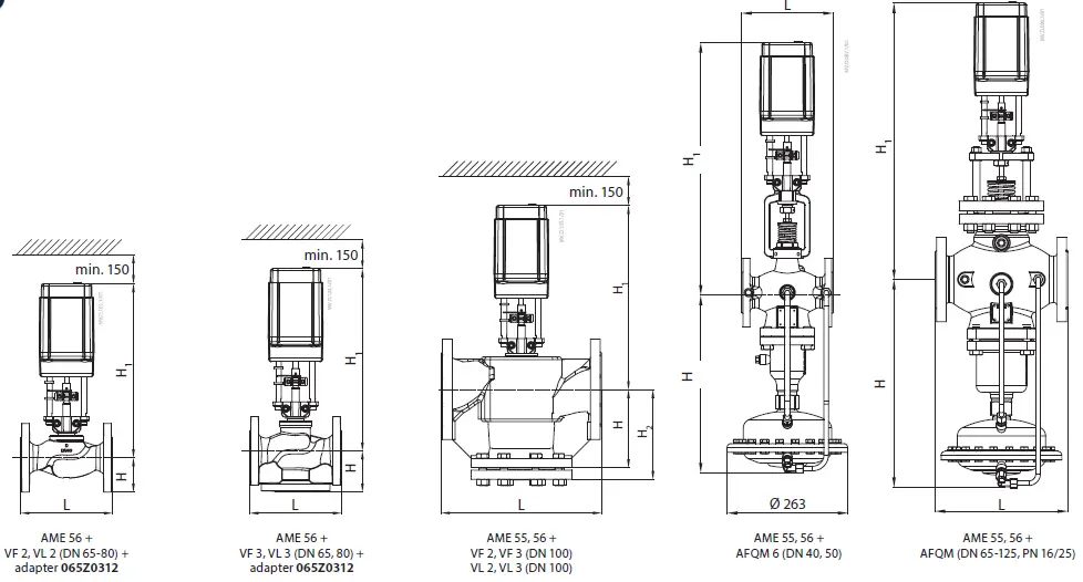
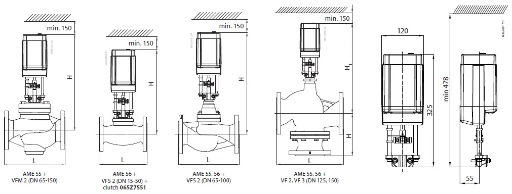
Dimensions ➎
| Part Name | Hazardous Substances Table | |||||
| Lead (Pb) | Mercury (Hg) | Cadmium (Cd) | Hexavalent Chromium (Cr(VI)) | Polybrominated biphenyls (PBB) | Polybrominated diphenyl ethers (PBDE) | |
| Reducer guide | X | O | O | O | O | O |
| Holder nut | X | O | O | O | O | O |
| Position indicator | X | O | O | O | O | O |
| Bush spring | X | O | O | O | O | O |
| Limiters | X | O | O | O | O | O |
| Gears | X | O | O | O | O | O |
| O: Indicates that this hazardous substance contained in all of the homogeneous material for this part is below the limit requirement in GB/T 26572; | ||||||
| X: Indicates that this hazardous substance contained in at least one of the homogeneous material for this part is above the limit requirementw in GB/T 26572; | ||||||


