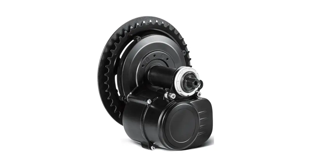
![]() TSDZ2 Central Motor Drive System
TSDZ2 Central Motor Drive System
Installation Guide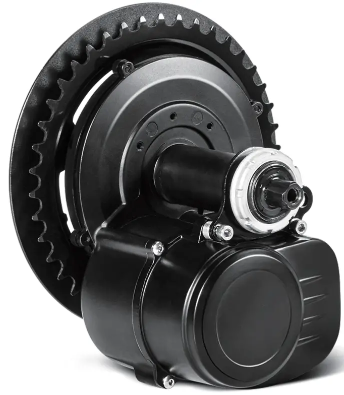 TSDZ2 Central Motor Drive System
Installation manual
TSDZ2 Central Motor Drive System
Appreciate for purchasing YOSE POWER electric bicycle Kits
Motor Installation Process
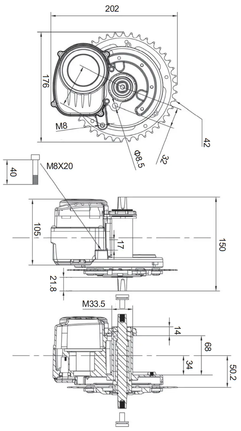
Step1 Check the dimension of BB axle, the length should be 68±0.15mm or 73±0.15mm, internal bore diameter Ø 33.6-33.8mm.
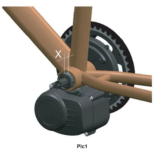
Step2 Push the motor axle sleeve into the bike BB.
Attention:
- the motor axle must be pushed completely to the end, ensure the outside axle sleeve lenght X=16mm(BB=68mm) or X=11mm(BB=73mm), as below Pic1.
- The motor case should not contact or interfere the frame fox, down tube, middle tube and etc. after pushing to the end. Otherwise it will make the motor shell deformation, creat noise and even damage the motor.
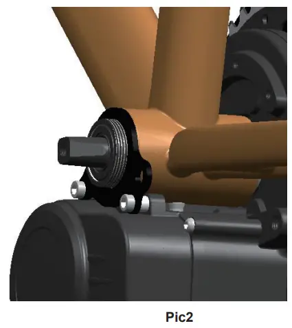
Step3: Install Securing plate. Please refer to Pic2.
- Put securing plate onto BB axle.
- Put 2 washers between motor and securing plate(BB=68mm)or put 4 washers between motor and securing plate(BB=73mm)
- Fix securing plate and motor using 2 pcs of M5×16 screws(BB=68mm) or 2 pcs of M5×24 screws(BB=73mm
 Put securing plate onto BB axle.
 Fix securing plate and motor using 2 pcs screws.
Step4 Fix M33.5 screw with BB axle using special tool by 40N·m torque.
Please refer to Pic3.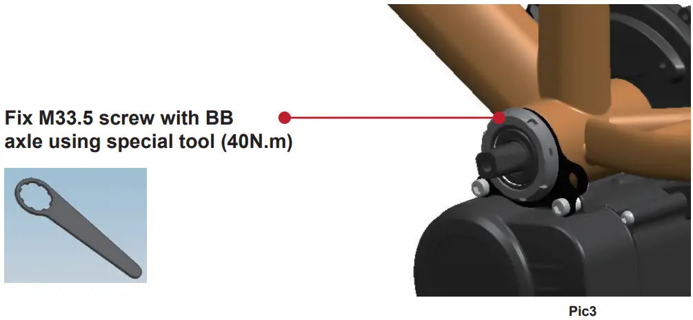
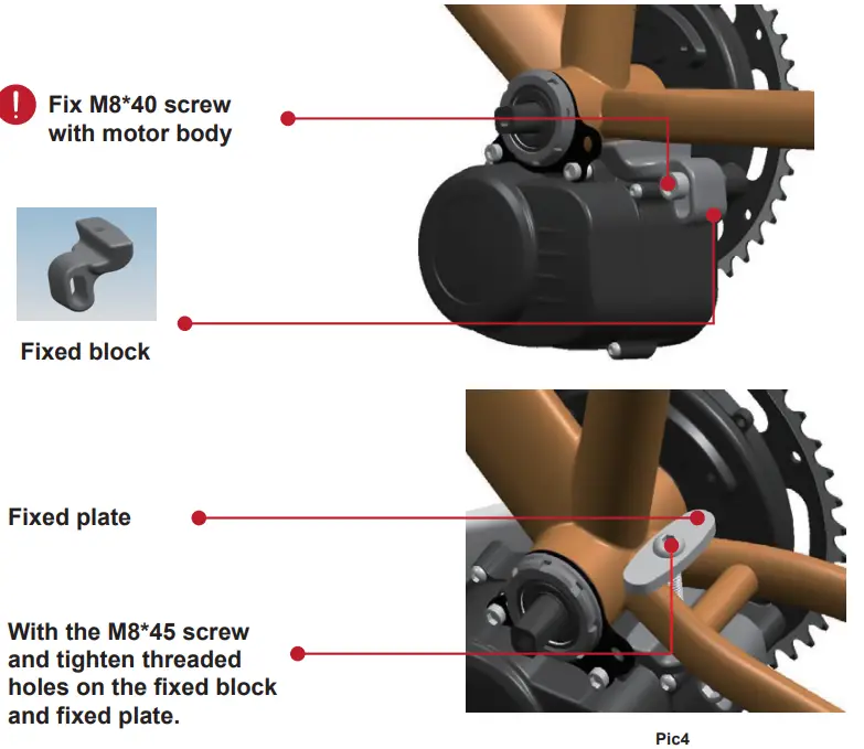
Step5: Fix Motor body with Frame. Please refer to Pic4.
- Fix M8*40 connection motor body and fixed block at this site, do not tighten.
- With the M8 * 45 screw and tighten threaded holes on the fixed block and fixed plate.
Step6: Using 40N.m torque to fix this M8*40 screw again. Please refer to Pic5. 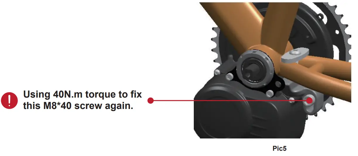
Step7: Cranks installation.
Fix Cranks using M8×14 screws, the locking torque is 40N.m. 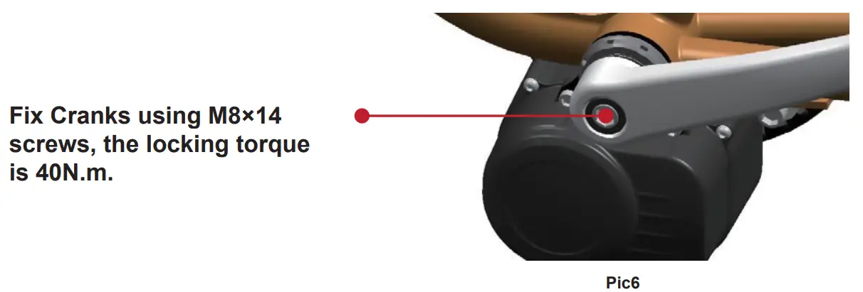
Display Installation Process
Step1 Install VLCD5 display. Please refer to Pic7.
Fix LCD display with handlebar using 2pcs of M4×14 bolts and 2pcs of M4 screws
The fixing support has 2 specifications: φ22.2 and φ32 users should be clear when placing orders. 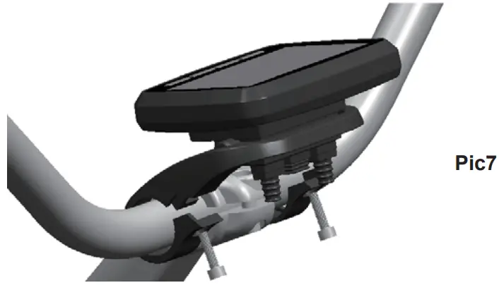
Step2 : Install left hand remote control buttons. Please refer to Pic8.
Use 2 M2.5×10 inner hexagon cylindrical head screws to fix the operation switch in the position shown in the figure 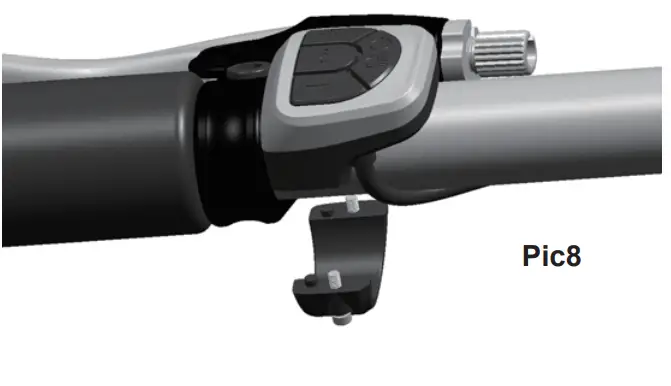
Detection vehicle speed sensor Installation
There is one vehicle speed sensor: CGQS8.
The installation method is as follows:
Step1: sensor Installation Pic9
With the two ribbons will speed sensor pedestal fixed on the frame flat after a fork
Step2: magnetic steel base Installation Pic9
Install the magnetic steel seat on the rear wheel spokes with the magnetic steel face toward the sensor and the magnetic steel center aligned with the protruding mark on the sensor.
Step3: Ensure the distance between magnetic steel surface and sensor Pic9
CGQS8——– not adjustable, ensure the distance between sensor and magnetic steel surface is 5-15mm.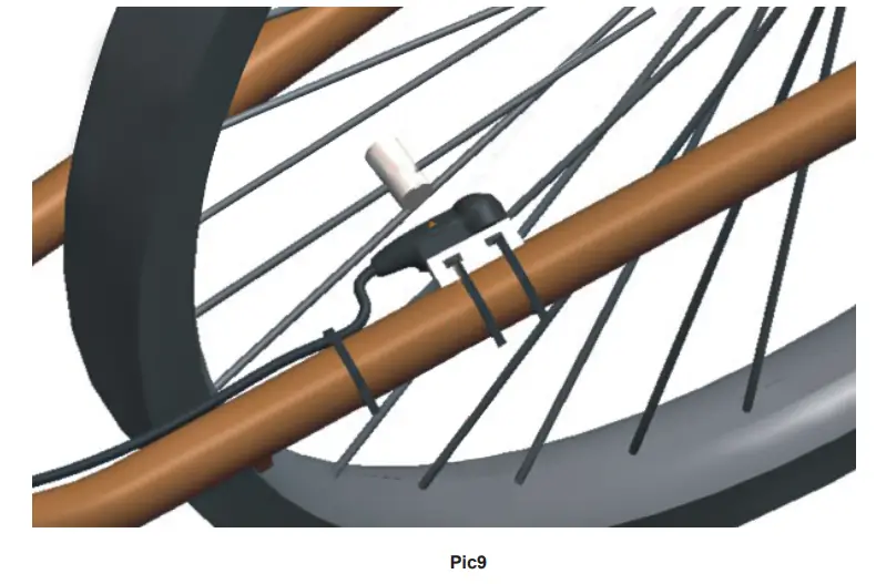
System connection
Step1plug in the operator and instrument.
Step2 plug the power brake into the base of the meter. This system can be without power brake;
Step3 insert the plug-in of the instrument and the central motor.
Step4 insert the plug-in of the vehicle speed sensors and the central motor.
Step5 connect the two power sources of the central motor to the battery.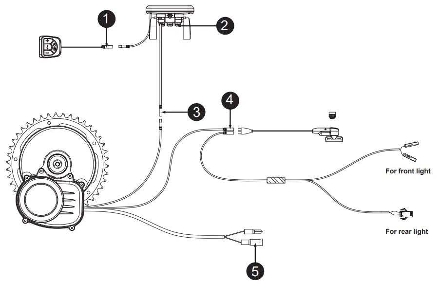
The wiring diagram
Parts List
- TSDZ2 central motor …………………………….×1
- VLCD5 display……………………………………… ×1
- VLCD5 display base(Ø22.5 and Ø32)…………………….. ×2
- Left side operation switch…………………………….. ×1
- Brake(left and right)……………………………………………. ×1
- Speed sensor CGQS8(with magnet) ……………………………….×1
- Securing plate ……………………………………………………………×1
- M33.5mm screw……………………………………………… ×1
- Fixed plate………………………………………………………… ×1
- Fixed block ………………………………………………………×1
- M8×45 screw …………………………………………×1
- M5×16 stainless steel screw(for 68 axle BB) ……………..×2
M5×24 stainless steel screw(for 73 axle BB)………………….. ×2 - Ø35×1mm washer …………………………………………………………..×1
- Ø35×2mm washer……………………………………………………. ×1
- Ø5×5 aluminum washer(for 68 axle BB)…………………………… ×2
Or Ø5×5 aluminum washer(for 73 axle BB)…………………… ×4 - Special installation tool …………………………………………………………..×1
- Cranks 170mm………………………………………………………………… ×2
![]() YOSE POWER CO.,LTD.
YOSE POWER CO.,LTD.
Add: Changxing County, Zhejiang Porvince, China.
E-mail:[email protected]


