![]() Installation Guide
Installation Guide
MR 50-5/50 V3.0
DMR 50-5/50 Dual Axes Drives
Notice:
This guide delivered subject to the following conditions and restrictions: This guide contains proprietary information belonging to Motor power Company Srl. Such information is supplied solely for the purpose of assisting users of the DMR 50-5/50 servo drive in its installation and configuration.
The text and graphics included in this manual are for the purpose of illustration and reference only. The specifications on which they are based are subject to change without notice.
Motor power Company and the Motor power Company logo are trademarks of Motor power Company Srl.
Information in this document is subject to change without notice.
| Version | Date | Author | Note |
| 1 | 1/11/2018 | Maurizio Piccinelli | Initial Release |
| 2 | 15/06/2020 | Maurizio Piccinelli | Few updates |
| 3 | 18/08/2021 | Piccinelli, Piacentini, Zivieri, Bassoli | LED, RS485 User Interface |
Product Presentation
2.1 General Description
The DMR 50-50/50 is a Motoroller servo drive especially designed for Motor Power Company Gearless motoroller.

We have 2 different available versions with different Digital I/O configuration (PNP,NPN)
The Device is able to operate one or 2 different devices independently, and is compatible with all the size 46 Gearless Motoroller and the Pallet Conveyor of Motor Power Company.
Safety Information
In order to achieve the optimum, safe operation of the MDR servo drive, it is imperative that you implement the safety procedures included in this installation guide. This information is provided to protect you and to keep your work area safe when operating the MDR and accompanying equipment. Please read this chapter carefully before you begin the installation process. Before you start, ensure that all system components are connected to earth ground.
Electrical safety is provided through a low-resistance earth connection. Only qualified personnel may install, adjust, maintain and repair the servo drive. A “qualified person” has the knowledge and authorization to perform tasks such as transporting, assembling, installing, commissioning and operating motors.
The DMR servo drive contains electrostatic-sensitive components that can be damaged if handled incorrectly. To prevent any electrostatic damage, avoid contact with highly insulating materials, such as plastic film and synthetic fabrics. Place the product on a conductive surface and ground yourself in order to discharge any possible static electricity build-up. To avoid any potential hazards that may cause severe personal injury or damage to the product during operation, keep all covers and cabinet doors shut. The following safety symbols are used in this manual:
| Warning: This information is needed to avoid a safety hazard, which might cause bodily injury. | |
| Caution: This information is necessary for preventing damage to the product or to other equipment. | |
| Note: This is auxiliary information that ensures the correct operation of the equipment. |
3.1 Warnings
| To avoid electric hazards to personnel and electrical contacts, never connect/disconnect the servo drive while the power source is on. | |
| Power cables can carry a high voltage, even when the motor is not in motion. Disconnect the DMR 50-50/50 from all voltage sources before it is open for servicing. | |
| The DMR 50-50/50 servo drive contains grounding conduits for electric current protection. Any disruption to these conduits may cause the device to become “hot” (live) and dangerous. | |
| After shutting off the power and removing the power source from your equipment, wait at least 3 minute before touching or disconnecting parts of the equipment that are normally loaded with electrical charges (such as capacitors or contacts). Measuring the electrical contact points with a meter before touching the equipment is recommended. |
3.2 Cautions
| The DMR 50-50/50 servo drive contains hot surfaces and electrically-charged components during operation. | |
| The maximum DC power supply connected to the instrument must comply with the parameters outlined in this guide. | |
| The DMR 50-50/50 servo drive must be connected to an approved 24VDC auxiliary power supply through a line that is separated from hazardous line voltages using reinforced or double insulation in accordance with approved safety standards. | |
| The DMR 50-50/50 series is designed to gets its power from a 48 VDC power source. Power to this device must be supplied by DC voltage, within the boundaries specified for the DMR. High voltages may damage the drive. The DC power supply voltage range is defined in this manual. Safety margins must be considered in order to avoid activating the under or over-voltage protection against line variations and/or voltage drop under load. The transformer should be able to deliver the required power to the drive (including peak power) without significant voltage drops (10% maximum). While driving high-inertia loads, the power supply circuit must be equipped with a shunt regulator; otherwise, the drive will be disabled whenever the capacitors are charged above the maximum voltage | |
| Before switching on the DMR, verify that all safety precautions have been observed and that the installation procedures in this manual have been followed. |
3.3 Directives and Standards
The DMR 50-50/50 servo drive conforms to the following industry safety standards:
| Safety Standard | Item |
| Designed in Compliance with UL508c and UL840 | Conformance to the following safety standards: • Power Conversion Equipment • Insulation Coordination, Including Clearance and Creepage distances of electrical equipment |
| Designed in compliance with UL60950 (formerly UL1950) | Safety of Information Technology Equipment, Including Electrical Business Equipment |
| In compliance with EN60204-1 | Low Voltage Directive, 73/23/EEC |
3.4 CE Mark Conformance
The DMR 50-50/50 servo drive is intended for incorporation in a machine or end product. The actual end product must comply with all safety aspects of the relevant requirements of the European Safety of Machinery Directive 98/37/EC as amended, and with those of the most recent versions of standards EN60204-1 and EN292-2 at the least.
According to Annex III of Article 13 of Council Directive 93/68/EEC, amending Council Directive 73/23/EEC concerning electrical equipment designed for use within certain voltage limits, the DMR 50-50/50 meets the provisions outlined in Council Directive 73/23/EEC. The party responsible for ensuring that the equipment meet the limits required by EMC regulations is the manufacturer of the end product.
3.5 Warranty Information
The products covered in this manual are warranted to be free of defects in material and workmanship and conform to the specifications stated either within this document or in the product catalogue description. All Motor Power Company products are warranted for a period of 12 months from the time of shipment. No other warranties, expressed or implied — and including a warranty of merchantability and fitness for a particular purpose — extend beyond this warranty.
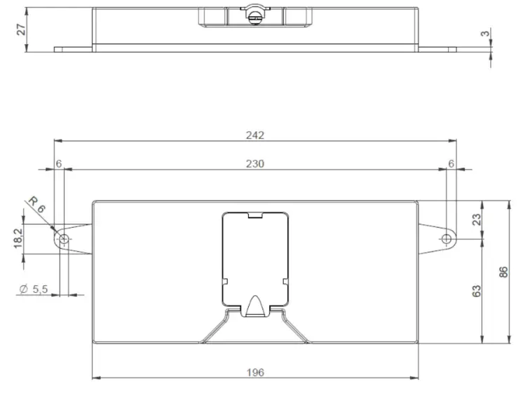
3.6 Drawings
3.7 Typical Installation
The device is designed to be installed on conveyor side
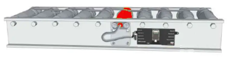 To fix the device to the conveyor side 2 x M5 screw are necessary.
3.8 Specifications
| Description | |
| Logic Supply | 24 Vdc +/- 5% |
| Minimum Supply Voltage | 12 Vdc |
| Nominal Supply Voltage | 48 Vdc |
| Maximum Supply Voltage | 60 Vdc |
| Nominal Current | 4:00 AM |
| Peak Current | 15 A |
| Output Power | 240 W |
| Efficiency @ rated Power | > 97% |
| PWM Switching Frequency | 10 kHz (Max) |
| Weight | Kg |
| Dimensions | 242x86x27 mm |
| Mounting Model | Wall Mount on Back side |
3.9 Environmental Conditions
| Description | |
| Operating ambient temperature | 0° ~ 40° C (32° ~ 104° F) |
| Storage temperature | -20° ~ +85° C ( -4° ~ +185° F) |
| Humidity | 90% maximum non-condensing |
| Protection level | IP20 |
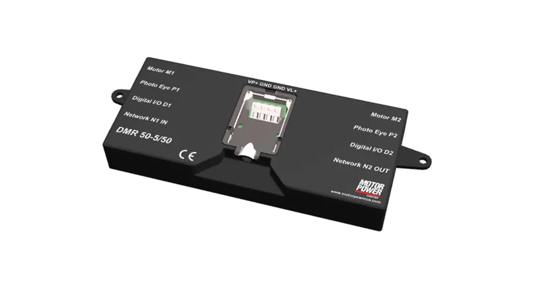
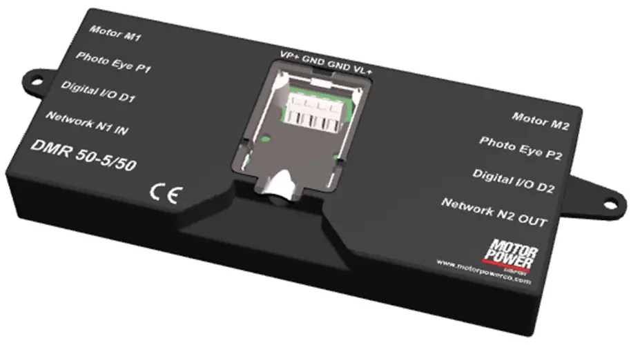
Location of Items
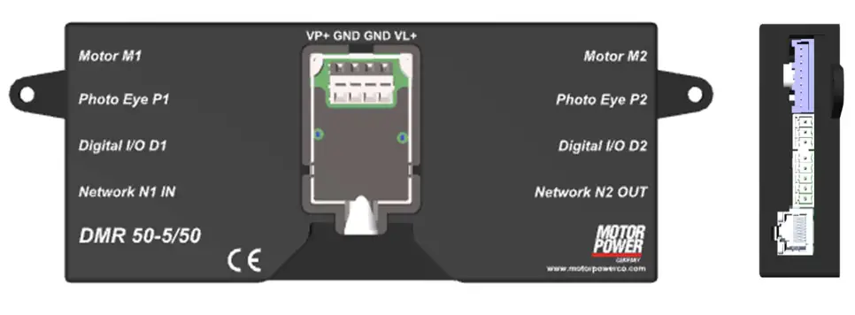 To use correctly the device the following items have to be identified:
| Object | Description |
| XP1 | Power Supply Connector |
| M1,M2 | Motor Connector |
| P1,P2 | Photo Eye Connector |
| D1,D2 | Function Connector |
| N1,N2 | Network Connector |
| L1,L2 | Led for Motor1 and Motor2 |
| L3,L4 | Network Led |
Wiring
5.1 Connector XP1 – Power Supply
The Connector Type is WAGO 236-404
The recommended power wires are fine-stranded conductor with ferrule plastic collar 0,25-1,5 mm²
| Pin | Function | Description |
| 1 | VP+ | Power Supply 48Vdc |
| 2 | GND | 0 Vdc |
| 3 | GND | 0 Vdc |
| 4 | VL+ | Logic Supply 24Vdc |
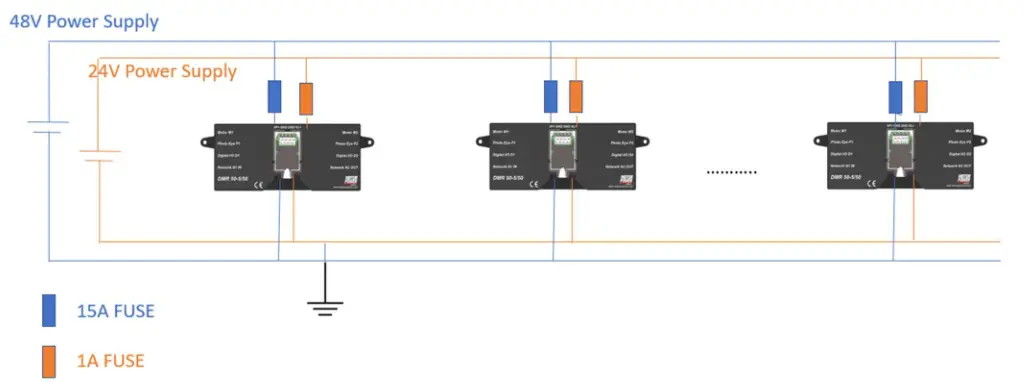
48 V dc switched-mode power supply, which can accept an overcurrent to handle the peak for 3 to 5s is recommended.
- The 24 Vdc Logic supply is protected with a 1 A fuse.
| Please provide a power supply that is enough powerful to in function of the type and the number of motorollers to be powered. | |
| Use Different power supply for Logic and Power. Motor Regeneration can damage the 24V Input Logic. |
5.2 Connector M1, M2 – Motor Connector
The connector is JST S09B-XASK-1, the mating connector on motor cable is JST XHP-9.
| Pin | Function | Description |
| 1 | Mw | Motor Phase w |
| 2 | Mv | Motor Phase v |
| 3 | Mu | Motor Phase u |
| 4 | Gnd | 0 Vdc |
| 5 | Hu | Hall Sensor u |
| 6 | Hv | Hall Sensor v |
| 7 | Hw | Hall Sensor w |
| 8 | Encoder Power Supply | 5 Vdc |
| 9 | Thermal Sensor | NTC Thermal sensor Input |
5.3 Connector P1, P2 – Photo Eye Connector
The connector is Phoenix Contact MC 1,5/ 3-G-3,5 – 1844223, the mating connector is Phoenix Contact MC 1,5/ 3-ST-3,5 – 1840379.
| Pin | Function | Description |
| 1 | Power Supply | 24 V power supply 200mA |
| 2 | Photo Eye Input | Input signal |
| 3 | Gnd | 0 Vdc |
5.3.1 Photo Eye internal connection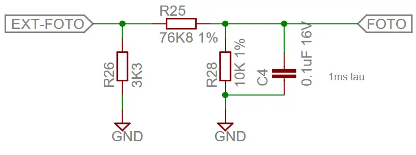
5.4 Connector D1, D2 – Standard Function Connector
The connector is Phoenix Contact MC 1,5/ 5-G-3,5 – 1844249, the mating connector is Phoenix Contact MC 1,5/ 5-ST-3,5 – 1840395.
| Pin | Function | Description | Type |
| 1 | Enable | Enable the Motor | Digital Input |
| 2 | Dir | Direction of Motor | Digital Input |
| 3 | Speed | Velocity of the motor | Analog Input |
| 4 | Error | Error on Motor | Digital Output |
| 5 | Out1 | Out1 | Digital Output |
5.4.1 Digital Input internal wiring
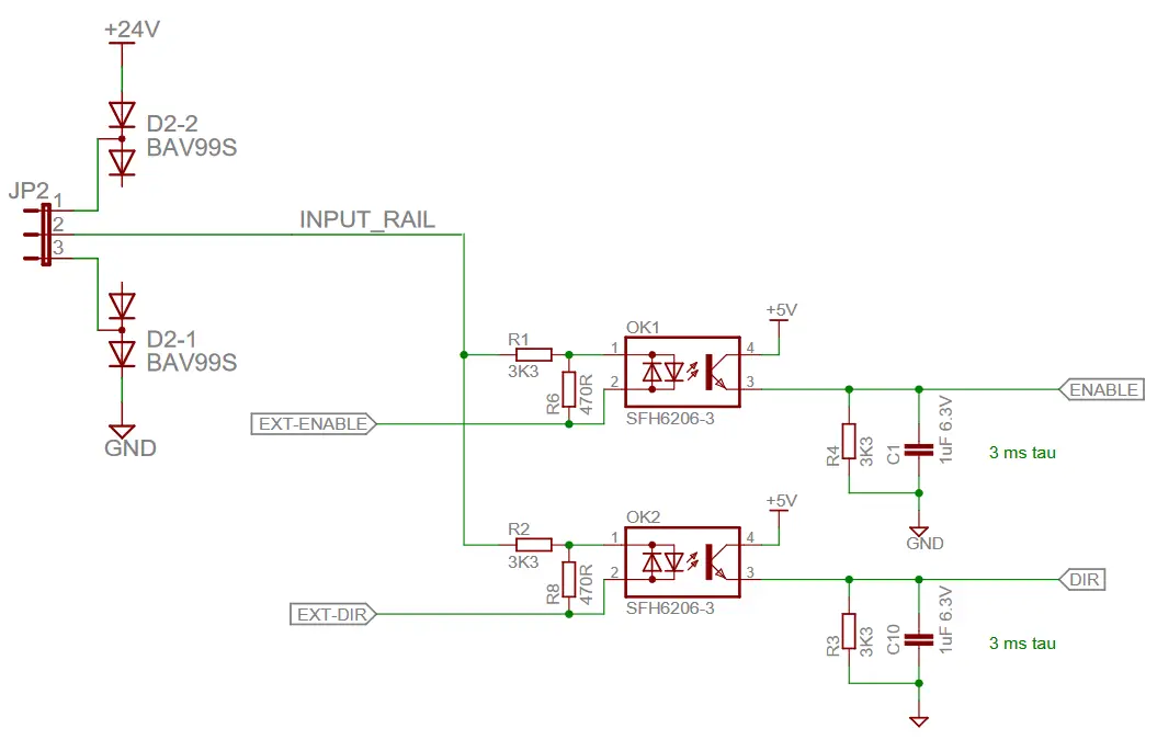
Typical input current @24Vcd is 7,2 mA
5.4.2 Analog Input internal wiring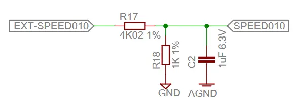 5.4.3 Digital Output Internal wiring
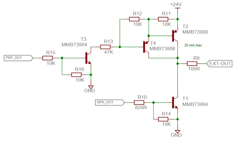 The output maximum current have to be < 25 mA. To protect the output is suggested to add an external resistance R > 860 Ω.
| In the event of a current ≥ 25 mA, there is a risk to damage the output transistor. |
5.5 Connector N1,N2 – Network Connection
The Connector is a standard RJ45 Female connector, Mating Connector RJ45 Male, is strongly recommended to use connector with metal case.
| Pin | Function | Description | Standard RJ-45 cable color |
| 1 | CAN H | CAN High | White/Orange |
| 2 | CAN L | CAN Low | Orange |
| 3 | GND???? | Not Connected | White/Green |
| 4 | DATA+ | RS 485 DATA+ | Blue |
| 5 | DATA- | RS 485 DATA- | White/Blue |
| 6 | Shield | Shield | Green |
| 7 | NC | Not Connected | White Brown |
| 8 | DI/DO | Input on N1, Output on N2 | Brown |
![]() To operate correctly the CAN Bus or the RS485 communications a 120Ω termination resistance must be added at both line side.
To operate correctly the CAN Bus or the RS485 communications a 120Ω termination resistance must be added at both line side.
Connection schematic
| Warning: Before commissioning, it is essential that the safety instructions in the relevant section are read and understood, and then observed! Non-observance can result in danger to persons or damage to the equipment. Disconnect the electrical power supply before any operation on the device. | |
| CAUTION: Incorrect connection of motor power electronics. The motor is not equipped with reverse polarity protection. Consequence: Destroying of the power electronics possible. Check the right polarity. | |
| NOTICE: Loops must be avoided for all grounding concepts. Shielded cable must be used for the whole cable system without interruption. Up to a length of 10m a common power and signal cable can be used. If the cable is longer than 10m it is recommended to separate power and signal in different shielded cables. When standard wires from Motor Power Company are used, the shielding must be spaciously applied inside the control cabinet. |
Failure to follow them can result in danger to persons or damage to the equipment.
6.1 Schematic circuit for power and logic supply
| CAUTION: Peak current by switching-on of a variety of series-connected motors. Consequence: Destroying of the integrated electronics possible. ► Using an adequate power supply. |
Default I/O Functionality
7.1 Run/Stop
This is the signal to use to enable disable the Device. Please consider that for encoder version 1s delay have to be considered at the first startup, to allow the current phase identification. Once the Device is enabled this will follow immediately the V-IN setpoint.
7.2 DIR – Direction of Rotation
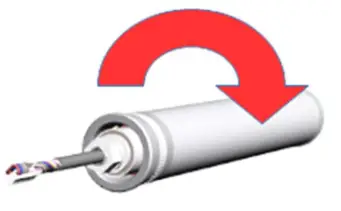
The default Direction of rotation is clock wise Motor A Flange if the DIR pin is set to Low.
7.3 V-IN – Speed Variation
Speed variation by an external analogue voltage from 0 to 10Vdc.
All the voltage above 10Vdc will be clamped to the 10Vdc value.
The default gains is applied 10 Vdc -> 800 rpm, and also the speed profiled is enable limiting the acceleration to 0,4 g (considering a roller diameter of 50 mm)
| Be careful to not exceed the 24Vdc to not damage the analogue input. | |
| Connect all the 0 VDC points of the external analogue power supply to the 0 Vdc of the XP1connector |
7.4 ERR – Error Signal
The signal is High when no error is present and Low when we have an error condition.
| When powering on and off, the error signal could be set. Do not consider this signal during 0.5s to power on, and 2s to power off. |
7.5 Customized I/O configuration
It’s possible using the Modbus RTU protocol od the Standard GUI to modify the digital input and output capability and logic levels of all the I/O present on the device. Please refer to the Software Manual to explore all the possible options.
LED Configuration
On the Device 7 LED are present, not all are used. Here below you can fint the position and the functions related to each one.
8.1 LED Map
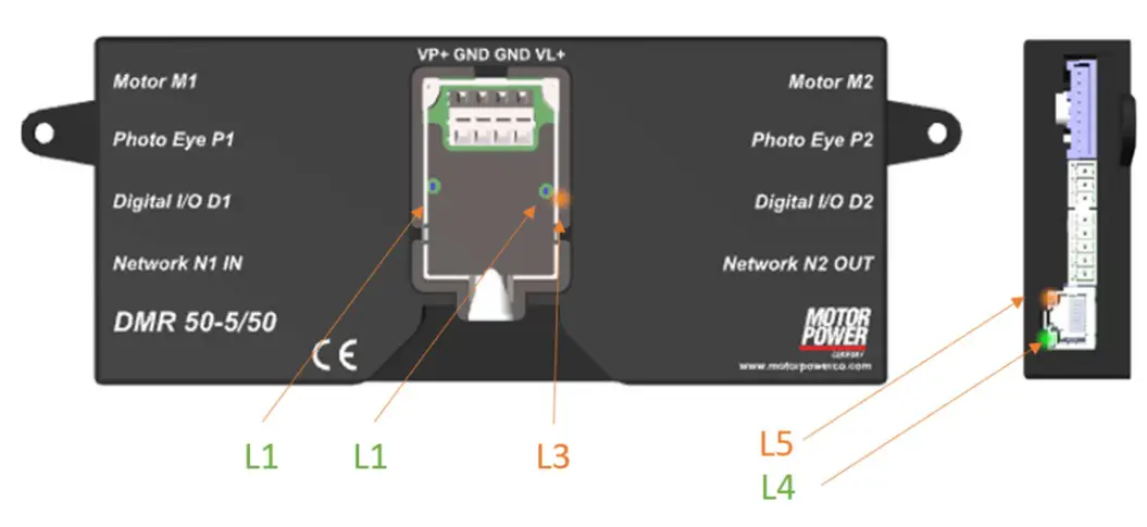
| LED | Color | Function | Note |
| L1 | Green | Axis M1 Status | |
| L2 | Green | Axis M2 Status | |
| L3 | Orange | Power Supply Status | |
| L4 | Green | Not Used | Same on both RJ-45* |
| L5 | Orange | Device Status | Same on both RJ-45* |
(* Please note that on the other side the RJ-45 are swapped)
8.2 L1 and L2 Axis Status
The LED L1 and L2 show the axis status.
| STATUS | DESCRIPTION |
| Blinking Fast | Axis OK and Disabled |
| Solid Green | Axis Enabled |
| Off | Axis Fault |
8.3 L3 Auxiliary Power Supply Status
The LED L3 show the Auxiliary Power Supply Status.
| STATUS | DESCRIPTION |
| Solid Green | Auxiliary Power Supply Ok |
| Off | No Logic Power Supply – Device Off |
8.4 L5 Device Status
The LED L5 show the Device Status Status.
| STATUS | DESCRIPTION |
| Switch off | Device Ok |
| Blinking | Fault occurred |
| Solid Orange | Device in Bootloader Mode |
Information on the motor
9.1 Motor Phase Angle
For a correct operation, the motor must have a correct electrical configuration.
| Specification | Value |
| Speed | 1000 rpm |
| Direction | Clockwise (A Motor Flange/Cable Side) |
| Reference Voltage | Concatenate |
| Tolerance | +/- 20 Electrical degrees |
The electrical configuration must follow this schema:
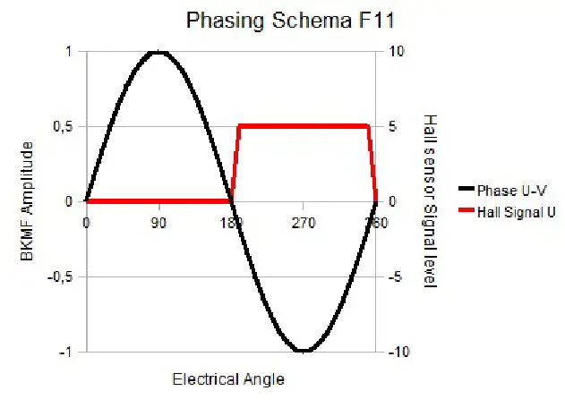 Every hall signal must be referred to the proper reference voltage:
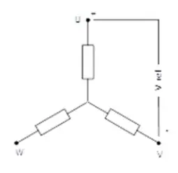
| Reference Voltage | Hall Signal Value |
| U-V | Hall Signal U |
| V-W | Hall Signal V |
| W-U | Hall Signal W |
9.2 Hall signal sequence
Hall sensor follow a grey code sequence. Rotating the motor Clockwise (front flange) we must find this configuration.
| Value | Hall U | Hall V | Hall W |
| 1 | 0 | 0 | 1 |
| 3 | 0 | 1 | 1 |
| 2 | 0 | 1 | 0 |
| 6 | 1 | 1 | 0 |
| 4 | 1 | 0 | 0 |
| 5 | 1 | 0 | 1 |
9.3 Motor Phase Sequence
Rotating clock-wise from motor A flange,
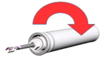 this is the correct phase sequence
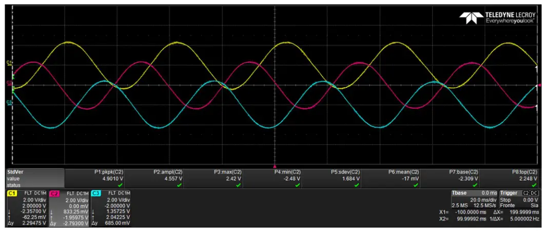 Image 1
Where:
C1 = Phase U, C2 = Phase V, C3 = Phase W
Standard Configuration Interface
10.1 Setup for Modbus RTU
Our standard USB to RS485 converter is USB2-H-5001-M that can be found on any major distributor web site. Any other converter with same capability can be used.
Below the correct dip-switch configuration.

![]() If the dip-switch will not have the proper configuration you will not be able to communicate with the device.
If the dip-switch will not have the proper configuration you will not be able to communicate with the device.
With standard RJ-45 cables this is the correct color sequence.
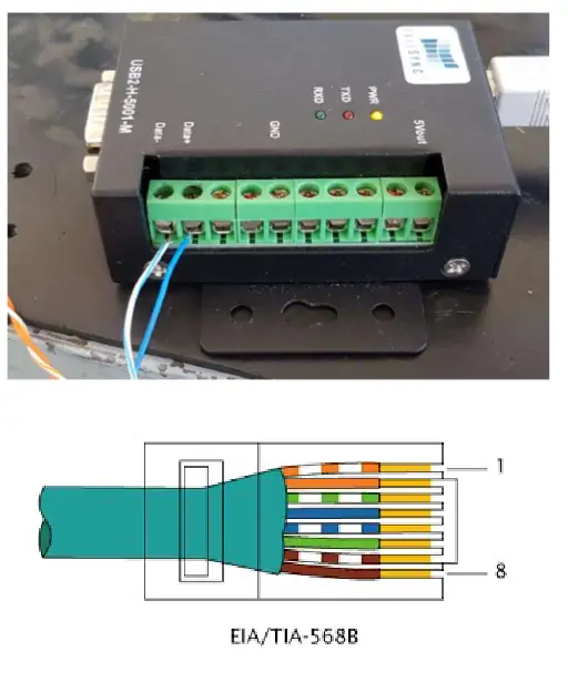 If you don’t have these wire color, please follow the N1,N2 connection schema.
10.2 Standard communication parameters
The standard configuration for the Modbus RTU communication is:
| Data | Value |
| Baud Rate | 460.8 |
| Data Bit | 8 |
| Stop Bit | 1 |
| Parity | No |
| Default Node | 247 |
Motor Power Conan s.r.l.
Via Leonardo Ca Vinci, 4
42024 Castelnovo Sotto Reggio Emilia – Italia
Tel. +39 0522 682710 – Fax +39 0522 683552
[email protected] – motorpowerco.com
Cap. Soc. 250.000.00e i.v. – R.E.A. di RE 175521
Iscr.Reg.Impr. di RE n.01308390358 – N. Mecc. RE 010210
C.F. e P.IVA IT 01308390358 ![]()


