![]()
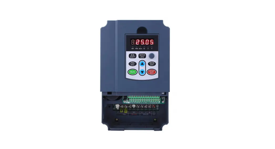
User Manual for
EV200 series Variable Frequency Drive
Outsize
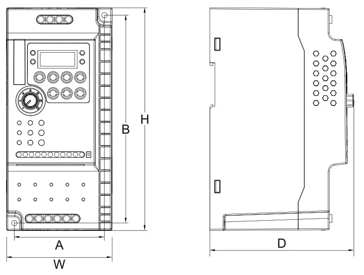
| Voltage | Model type | Power(kW) | Install size(mm) | outsize(mm) | Install hole | |||
| A | B | W | H | D | ||||
| Single phase 220V | EV200-0400G-S2 | 0. 4 |
60 |
129 |
73 |
143 |
112. 6 |
Ф4.4 |
| EV200-0750G-S2 | 0. 75 | |||||||
| EV200-1500G-S2 | 1. 5 | |||||||
| EV200-2200G-S2 | 2. 2 | |||||||
| Three phase 380V | EV200-0750G-T3 | 0. 75 | ||||||
| EV200-1500G-T3 | 1. 5 | |||||||
| EV200-2200G-T3 | 2. 2 | |||||||
| EV200-3700G-T3 | 3. 7 | 73 | 168 | 85. 5 | 180 | 116. 4 | Ф4.4 | |
| EV200-5500G-T3 | 5. 5 | |||||||
Standard Wiring Diagram
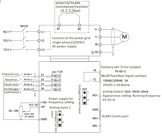
Wiring instrucons
| Terminal symbol | Function description |
| E | Grounding terminal |
| L1、L3 | Connect to the power grid single-phase (220Vac) AC power supply |
| L1、L2、L3 | Connected to the grid three-phase (380Vac) AC power supply |
| U,V,W | Connect a three-phase AC motor |
| B1 | Filter capacitor DC side voltage positive terminal |
| B2 | A DC braking resistor can be connected directly to B1 |
Technical specificaons
| Item | Specification | |
| Highest frequency | Vector control: 0~500Hz; V/F control: 0~500Hz | |
| Carrier frequency | 0.8kHz ~ 12kHz Carrier frequency can be adjusted automatically according to temperature characteristics | |
| Input frequency resolution | Digital setting: 0.01Hz Analog setting: maximum frequency × 0.025% | |
| control mode | without PG Vector(SVC),Feedback vector(FVC) and V/F control | |
| Start torque | G type: 0.5Hz/150%(SVC);0Hz/180%(FVC) P type: 0.5Hz/100% | |
| Speed range | 1:100 (SVC) | 1:1000 (FVC) |
| Speed control accuracy | ±0.5%(SVC) | ±0.02%(FVC) |
| Torque control accuracy | ±5%(FVC) | |
| Overload capacity | G type: 150% rated current 60sec; 180% rated current 3sec | |
Funcon Parameters Table
When PP-00 is set as a non-zero value, that is, the parameter protecon password is set. In the funcon parameter and the user changes the parameter mode, the parameter menu must enter the password correctly. It can cancel the password protecon funcon by seng PP-00 as 0.
The parameter menu in user-defined parameter mode is not password protected.
Group P and A include basic funcon parameters, group d includes the monitoring funcon parameters. The symbols in the funcon code table are described as follows:
“☆” : it is possible to modify the parameter when the drive in the stop or in the run status;
“★”: impossible;
“●”:the parameter is the actual measured value and can not be modified.
“*” : the parameter is a “factory parameter”, can be set only by the manufacturer, prohibit the user to operate.
| Function Code | Name | Setting Range | Default | Modify |
| P0 Group: Basic Function | ||||
| P0-01 | Motor 1 control mode | 0: No speed sensor vector control (SVC) 1: Speed sensor vector control (FVC) 2: V/F control | 2 | ★ |
| P0-02 | Command source selection | 0: Operation panel instruction channel 1: Terminal command channel 2:communication command channel | 0 | ☆ |
|
P0-03 |
Main frequency reference setting A channel selection | 0: digital setting (preset frequency P0-08, UP/DOWN can be modified, power is not memory) 1: digital setting (preset frequency P0-08, UP/DOWN can be modified, power-down memory 2: AI1 (Note: J4 jumper in the PANEL and AI1 connected to the keyboard potentiometer input, PORT and AI1 connected to the external terminal AI1 input) 3: Ai2 4: Ai3 5:High-speed pulse Inputsetting (S5) 6: multi-segment instructions 7: Simple PLC 8: PID 9: communication given 10: Reserved |
2 |
★ |
| P0-04 | Auxiliary frequency source B command input selection | With P0-03 (main frequency source A instruction input selection) | 0 | ★ |
| P0-05 | Auxiliay frequency source B Reference object selection | 0:relative to maximum frequency 1: relative to frequency source A | 0 | ☆ |
| P0-06 | Auxiliary frequency source B command range | 0%~150% | 100% | ☆ |
|
P0-07 |
Frequency source combination mode selection | Bit: frequency source selection 0: Main frequency source A 1: main and auxiliary operation results (operation relationship determined by ten) 2: Main frequency source A and auxiliary frequency source B switch 3: Main frequency source A and master and slave operation result switching 4: auxiliary frequency source B and master and slave operation result switching Ten: frequency source main and auxiliary operation relationship 0: main + auxiliary 1: main – auxiliary 2: the two maximum 3: the two minimum |
00 |
☆ |
| P0-08 | Preset frequency | 0.00Hz~max(P0-10) frequency | 50.00Hz | ☆ |
| P0-09 | Running direction | 0: same direction 1: opposite direction | 0 | ☆ |
| P0-10 | Max.output frequency | 50.00Hz~500.00Hz | 50.00Hz | ★ |
| P0-11 | Setting channel of frequency upper limit | 0: P0-12 is set 1:AI1(Note:J6jump) 2: AI2 3: AI3 4: High-speed pulse setting (S5) 5: communication given | 0 | ★ |
| P0-12 | Frequency reference upper limit | Upper limit P0-10 P0-14~max frequency | 50.00Hz | ☆ |
| P0-13 | Frequency reference upper limit offset | 0.00Hz~frequency max. P0-10 | 0.00Hz | ☆ |
| P0-14 | Frequency Reference lower limit | 0.00Hz~frequency upper limit P0-12 | 0.00Hz | ☆ |
| P0-15 | Carrier frequency | 0.8KHz~12.0KHz | Model dependent | ☆ |
| P0-16 | Carrier frequency adjusted with temperature | 0: Disabled 1: Enabled | 1 | ☆ |
| P0-17 | Acceleration time 1 | 0.00s~65000s | Model dependent | ☆ |
| P0-18 | Deceleration time 1 | 0.00s~65000s | Model dependent | ☆ |
| P0-19 | Acceleration/ Deceleration time unit | 0: 1s 1: 0.1s 2: 0.01s | 1 | ★ |
| P0-21 | Frequency offset of auxiliary frequency setting channel for main and auxiliary calculation | 0.00Hz~max.frequency P0-10 | 0.00Hz | ☆ |
| P0-22 | Frequency reference resolution | 2: 0.01Hz | 2 | ★ |
| P0-23 | Retentive of digital setting frequency upon stop | 0: do not remember 1: memory | 1 | ☆ |
| P0-24 | Motor parameter group selection | 0: 1st motor parameter 1: 2nd motor parameter | 0 | ★ |
| P0-25 | Acceleration/ Deceleration time base frequency | 0:maximum (P0-10) 1: Set frequency 2: 100Hz frequency | 0 | ★ |
| P0-26 | Base frequency for UP/DOW modification during running | 0: Run frequency 1: Set frequency | 0 | ★ |
|
P0-27 |
The run command is tied to the main frequency source A command selection | Bit: Operation panel command Bind frequency source selection 0: no binding 1: Digital setting frequency 2: AI1 (Note: J6 jumper) 3: AI2 4: AI3 5: High-speed pulse input setting (S5) 6: multi-speed 7: Simple PLC 8: PID 9: communication given Ten: Terminal Command Binding Frequency Source Selection Hundreds: communication command binding frequency source selection |
0 |
☆ |
| P0-28 | Serial port communication protocol | 0: Modbus communication | 0 | ☆ |
| P1 Group: Motor 1 Parameters | ||||
| P1-00 | Motor type selection | 0: ordinary asynchronous motor 1: Variable frequency asynchronous motor | 0 | ★ |
| P1-01 | Rated motor power | 0.1KW~1000.0KW | Model dependent | ★ |
| P1-02 | Rated motor voltage | 1V~2000V | Model dependent | ★ |
| P1-03 | Rated motor current | 0.01 to 655.35A (AC drive power ≤ 55 KW) 0.1 to 6553.5A (AC drive power > 55 KW) | Model dependent | ★ |
| P1-04 | Rated motor frequency | 0.01Hz~max. frequency | Model dependent | ★ |
| P1-05 | Rated motor speed | 1rpm~65535rpm | Model dependent | ★ |
| P1-06 | Stator resistance | 0.001Ω~65.535Ω(AC drive power≤55KW) 0.0001Ω~6.5535Ω(AC drive power>55KW) | Auto- tuning dependent | ★ |
| P1-07 | Rotor resistance | 0.001Ω~65.535Ω(AC drive power≤55KW) 0.0001Ω~6.5535Ω(AC drive power>55KW) | Auto- tuning dependent | ★ |
| P1-08 | Leakage inductive reactance | 0.01mH~655.35mH(AC drive power≤55KW) 0.001mH~65.535mH ( AC drive power>55KW) | Auto- tuning dependent | ★ |
| P1-09 | Mutual inductive reactance | 0.1mH~6553.5mH(AC drive power≤55KW) 0.01mH~655.35mH(AC drive power>55KW) | Auto- tuning dependent | ★ |
| P1-10 | No-load current | 0.01A~P1-03(AC drive power≤55KW) 0.1A~P1-03(AC drive power>55KW) 0.1A~P1-03(AC drive power>55KW) | Auto- tuning dependent | ★ |
| P1-27 | Encoder pulses per revolution | 1~65535 | 1024 | ★ |
| P1-28 | Encoder type | 0: ABZ incremental encoder 2: Resolver | 0 | ★ |
| P1-30 | A/B phase sequence of ABZ incremental encoder | 0: Forward 1: Reserve | 0 | ★ |
| P1-34 | Number of pole pairs of resolver | 1~65535 | 1 | ★ |
| P1-36 | Encoder wire-break fault detection time | 0.0: no operation 0.1s~10.0s | 0.0s | ★ |
|
P1-37 | Motor auto-tuning method selection | 0: no operation 1: Asynchronous machine static part of the parameters of self-learning 2: asynchronous machine dynamic complete self-learning 3: asynchronous machine static complete self-learning |
0 |
★ |
| P2 Group: Vector Control Parameters | ||||
| P2-00 | Speed loop proportional gain 1 | 1~100 | 30 | ☆ |
| P2-01 | Speed loop integral time 1 | 0.01s~10.00s | 0.50s | ☆ |
| P2-02 | Switchover frequency 1 | 0.00~P2-05 | 5.00Hz | ☆ |
| P2-03 | Speed loop proportional gain 2 | 1~100 | 20 | ☆ |
| P2-04 | Speed loop integral time 2 | 0.01s~10.00s | 1.01.00s0s | ☆ |
| P2-05 | Switchover frequency 2 | P2-02~max frequency (P0-10) | 10.00Hz | ☆ |
| P2-06 | SVC/FVC slip compensation gain | 50%~200% | 100% | ☆ |
| P2-07 | SVC Speed feedback filter time constant | 0.000s~0.100s | 0.015s | ☆ |
| P2-09 | Torque upper limit command channel selection under speed control | 0: function code P2-10 setting 1: AI1 2: AI2 3: AI3 4: high-speed pulse input setting (S5) 5: communication given 6: MIN (AI1, AI2) 7: MAX (AI1, AI2) 1-7 option full scale corresponds to P2-10 | 0 | ☆ |
| P2-10 | Digital setting of torque limit in speed control | 0.0%~200.0% | 150.0% | ☆ |
|
P2-11 |
Torque limit source in speed control (in regenerative state) | 0: Function code P2-12 setting (no distinction between electric and power generation) 1: AI1 2: AI2 3: AI3 4:High-speed pulse input setting 5: communication given 6: MIN (AI1, Ai2) 7: MAX (AI1, AI2) 8: Function code P2-12 setting 1-7 The full scale of the option corresponds to P2-12 |
0 |
☆ |
| P2-12 | Digital setting of torque limit in speed control (in regenerative state) | 0.0%~200.0% | 150.0% | ☆ |
| P2-13 | Excitation adjustment proportional gain | 0~60000 | 2000 | ☆ |
| P2-14 | Excitation adjustment integral gain | 0~60000 | 1300 | ☆ |
| P2-15 | Torque adjustment proportional gain | 0~60000 | 2000 | ☆ |
| P2-16 | Torque adjustment integral gain | 0~60000 | 1300 | ☆ |
| P2-17 | Speed loop integral separation selection | 0: Disabled 1: Enabled | 0 | ☆ |
| P2-20 | Max output voltage | – | – | – |
| P2-21 | Max. torque coefficient of field weakening area | 50~200% | 100% | ☆ |
| P2-22 | Regenerative power limit selection | 0: Disabled 1: Enabled | 0 | ☆ |
| P2-23 | Regenerative power limit | 0~200% | Model dependent | ☆ |
| P3 Group: V/F Control Parameters | ||||
| P3-00 | V/F curve setting | 0: Straight line V/F 1: multipoint V/F 2: square V/F 3: 1.2 Power V/F 4: 1.4 Power V/F 6: 1.6 Power V/F 8: 1.8 power V/F 9: Reserved 10: VF complete separation mode 11: VF semi-separation mode | 0 | ★ |
| P3-01 | Torque boost | 0.0%: (Ineffective) 0.1%~30.0% | Model dependent | |
| P3-02 | Cut-off frequency of torque boost | 0.00Hz~max. frequency | 50.00Hz | ★ |
| P3-03 | Multi-point V/F frequency1 | 0.00Hz~P3-05 | 0.00Hz | ★ |
| P3-04 | Multi-point V/F voltage 1 | 0.0%~100.0% | 0.0% | ★ |
| P3-05 | Multi-point V/F frequency 2 | P3-03~P3-07 | 0.00Hz | ★ |
| P3-06 | Multi-point V/F voltage 2 | 0.0%~100.0% | 0.0% | ★ |
| P3-07 | Multi-point V/F frequency 3 | P3-05~rated motor frequency (P1-04) | 0.00Hz | ★ |
| P3-08 | Multi-point V/F voltage 3 | 0.0%~100.0% | 0.0% | ★ |
| P3-09 | Slip compensation gain | – | – | – |
| P3-10 | V/F over-excitation gain | 0~200 | 64 | ☆ |
| P3-11 | V/F oscillation suppression gain | 0~100 | 40 | ☆ |
|
P3-13 |
Voltage source for V/F separation | 0: digital setting (P3-14) 1: AI1 (Note: J6 jumper) 2: AI2 3: AI3 4: High-speed pulse input setting (S5) 5: multi-segment instructions 6: Simple PLC 7: PID 8: communication given Note: 100.0% corresponds to the motor rated voltage |
0 |
☆ |
| P3-14 | Digital setting of voltage for V/F separation | 0V~rated motor voltage | 0V | ☆ |
| P3-15 | Voltage rise time of V/F separation | 0.0s~1000.0s Note: 0V to rated motor voltage | 0.0s | ☆ |
| P3-16 | Voltage decline time of V/F separation | 0.0s~1000.0s Note: time of 0V to rated motor voltage | 0.0s | ☆ |
| P3-17 | Stop mode selection for V/F separation | 0: Frequency and voltage declining to 0 independently 1: Frequency declining after voltage declines to 0 | 0 | ☆ |
| P3-18 | Current limit level | 50~200% | 150% | ★ |
| P3-19 | Current limit selection | 0: useless 1: useful | 1 | ★ |
| P3-20 | Current limit gain | 0~100 | 20 | ☆ |
| P3-21 | Compensation factor of speed multiplying current limit level | 50~200% | 50% | ★ |
| P3-22 | Voltage limit | 650V~800.0V | 770V | ★ |
| P3-23 | Voltage limit selection | 0: useless 1: useful | 1 | ★ |
| P3-24 | Frequency gain for voltage limit | 0~100 | 30 | ☆ |
| P3-25 | Voltage gain for voltage limit | 0~100 | 30 | ☆ |
| P3-26 | Frequency rise threshold during voltage limit | 0~50Hz | 5Hz | ★ |
| P4 Group: Input Terminals | ||||
| P4-00 | S1 function selection | 0: no function 1: Forward run (FWD) or run command 2: reverse run (REV) or positive and negative running direction (Note: set 1, 2 to be used with P4-11) 3:three-wire operation control 4: forward jog (FJOG) 5: reverse jog (RJOG) 6: Terminal UP 7: Terminal DOWN 8: free parking 9: Fault reset (RESET) 10: run pause 11: External fault normally open input 12:Multi-step command terminal 1 13:Multi-step command terminal 2 14:Multi-step command terminal 3 15:Multi-step command terminal 4 16: Acceleration/Deceleration time selection terminal 1 17:Acceleration/Deceleration time selection terminal 2 18: Frequency command switching 19: UP/DOWN setting clear(terminal, keyboard) 20: control command to switch terminal 1 21: Acceleration/Deceleration is prohibited 22: PID pause 23: Easy PLC status reset 24: Wobble is suspended 25: Counter input 26: Counter reset 27: Length count input 28: Length reset 29: Torque control disabled 30: High-speed pulse input (only valid for S5) 31: Reserved 32: Immediate DC braking 33: External fault normally closed input 34: Frequency modification enabled 35: PID direction is reversed 36: External parking terminal 1 37:control command to switch terminal 2 38: PID integral is paused 39: Frequency source A and preset frequency switching 40: Frequency source B and preset frequency switching 41: Motor terminal selection function 42: Reserved 43: PID parameter switch 44: User defined fault 1 45: user defined fault 2 46:Speed control/torque control switching 47: Emergency stop 48: External parking terminal 2 49:Decelerationof DC braking 50: This run time is cleared 51:two-wire/three-wire switch 52:Reverse frequency disabled 53-59: Reserved | 1 | ★ |
| P4-01 | S2 function selection | 4 | ★ | |
| P4-02 | S3 function selection | 9 | ★ | |
| P4-03 | S4 function selection | 12 | ★ | |
| P4-04 | S5 function selection | 13 | ★ | |
| P4-05 | S6 function selection | 0 | ★ | |
| P4-06 | S7 function selection | 0 | ★ | |
| P4-07 | S8 function selection | – | ★ | |
| P4-08 | Reserved | – | ★ | |
| P4-09 | Reserved | – | ★ | |
| P4-10 | S1~S4 filter time | 0.000s~1.000s | 0.010s | ☆ |
| P4-11 | Terminal control mode | 0: two lines 1 1: two lines 2 2: three lines 1 3: three lines 2 | – | ★ |
| P4-12 | Terminal UP/DOWN N rate | 0.001Hz/s~65.535Hz/s | 1.00Hz/s | ☆ |
| P4-13 | AI curve 1 min. input | 0.00V~P4-15 | 0.00V | ☆ |
| P4-14 | Corresponding percentage of AI curve 1 min. input | – 100.0%~+100.0% | 0.0% | ☆ |
| P4-15 | AI curve 1 max. input | P4-13~+10.00V | 10.00V | ☆ |
| P4-16 | Corresponding percentage of AI curve 1 max. input | – 100.0%~+100.0% | 100.0% | ☆ |
| P4-17 | AI1 filter time | 0.00s~10.00s | 0.10s | ☆ |
| P4-18 | AI curve 2 min. input | 0.00V~P4-20 | 0.00V | ☆ |
| P4-19 | Corresponding percentage of AI curve 2 min. input | – 100.0%~+100.0% | 0.0% | ☆ |
| P4-20 | AI curve 2 max. input | P4-18~+10.00V | 10.00V | ☆ |
| P4-21 | Corresponding percentage of AI curve 2 max. input | – 100.0%~+100.0% | 100.0% | ☆ |
| P4-22 | AI2 filter time | 0.00s~10.00s | 0.10s | ☆ |
| P4-23 | AI3 curve min. input | – 10.00V~P4-25 | – 10.0V | ☆ |
| P4-24 | Corresponding percentage of AI curve 3 min. input | – 100.0%~+100.0% | – 100.0% | ☆ |
| P4-25 | AI curve 3 max. input | P4-23~+10.00V | 10.00V | ☆ |
| P4-26 | Corresponding percentage of AI curve 3 max. input | – 100.0%~+100.0% | 100.0% | ☆ |
| P4-27 | AI3 filter time | 0.00s~10.00s | 0.10s | ☆ |
| P4-28 | Pulse min. input | 0.00kHz~P4-30 | 0.00KHz | ☆ |
| P4-29 | Corresponding percentage of pulse min. input | – 100.0%~100.0% | 0.0% | ☆ |
| P4-30 | Pulse max. input | P4-28~100.00kHz | 50.00KHz | ☆ |
| P4-31 | Corresponding percentage of pulse max. input | – 100.0%~100.0% | 100.0% | ☆ |
| P4-32 | Pulse filter time | 0.00s~10.00s | 0.10s | ☆ |
|
P4-33 |
AI curve selection | Bit: AI1 curve selection 1: curve 1 (2 points, see P4-13~P4-16) 2: Curve 2 (2 points, see P4-18~P4-21) 3: curve 3 (2 points, see P4-23~P4-26) 4: curve 4 (4 points, see A6-00~A6-07) 5: curve 5 (4 points, see A6-08~A6-15) Ten: AI2 curve selection, ibid Hundreds:AI3 curve selection, ibid |
321 |
☆ |
| P4-34 | Setting selection when AI less than min. input | Bit: AI1 is lower than the minimum input setting 0: corresponds to the minimum input setting 1: 0.0% Ten: AI2 is lower than the minimum input setting, ibid Hundreds: AI3 is lower than the minimum input setting, ibid | 000 | ☆ |
| P4-35 | S1 delay | 0.0s~3600.0s | 0.0s | ★ |
| P4-36 | S2 delay | 0.0s~3600.0s | 0.0s | ★ |
| P4-37 | S3 delay | 0.0s~3600.0s | 0.0s | ★ |
| P4-38 | S1~S5 active mode selection 1 | 0: active high 1: active low Bit: S1 Ten: S2 Hundred places: S3 Thousands of bits: S4 Million: S5 | 00000 | ★ |
| P5 Group: Output Terminals | ||||
|
P5-02 |
Relay 1 function selection ( TA-TC) | 0: pulse output (HDP) 1: Switching output (HDY) |
2 |
☆ |
| 0: No output 1: The inverter is running 2: fault output (fault stop) 3: Frequency level detection FDT1 output 4: frequency arrives 5: Zero speed operation (no output at shutdown) 6: motor overload pre-alarm 7: Inverter overload pre-alarm 8: Set the count value to reach 9: Specifies that the count value arrives 10: length to reach 11: PLC cycle is complete 12: The cumulative run time arrives 13: Frequency limit 14: Torque limit 15: Ready to run 16: AI1>AI2 17: upper limit frequency arrival 18: Lower frequency arrival (operation related) 19:Undervoltage status output 20: communication settings 21:Positioning completed (reserved) 22:positioning close (reserved) 23: zero speed running 2 (also output when stopped) 24: The total power-up time arrives 25: Frequency level 26: Frequency 1 reaches the output 27: Frequency 2 reaches the output 28: current 1 reaches the output 29: current 2 reaches the output 30: Timing arrival output 31: AI1 input is overrun 32: Underload 33: reverse running 34: zero current state 35:Module temperature arrives 36:Output current is exceeded 37: Lower frequency arrival (shutdown also output) 38: Alarm output (continued) 39:Motor over temperature warning 40: This run time arrives 41: fault output (for free stop fault), and under voltage is not output | ||||
|
P5-07 |
A01 Output function selection | 0:Operating frequency 1:Frequency setting 2:Output current 3:Output torque 4:Output power 5:Output voltage 6:High-speed pulse input(100%corresponding100.0khz) 7:AI1 8:AI2 9:AI3 10:length 11:Count value 12:Communication settings 13:Motor speed 14:Output current:(100% corresponding 1000.0A) 15:Output voltage(100% Corresponding 1000.0V) 16:Motor output torque(Actual value, Percentage relative to motor) |
0 |
☆ |
| P5-10 | A01 Zero bias coefficient | – 100.0%~+100.0% | 0.0% | ☆ |
| P5-11 | A01 gain | – 10.00~+10.00 | 1.00 | ☆ |
| P6 Group: Start/Stop Control | ||||
| P6-00 | Start mode | 0: Direct start 1: Catching a spinning motor 2: Pre-excited start 3: SVC quick start | 0 | ☆ |
| P6-01 | Mode of catching a spinning motor | 0: From stop frequency 1: From 50Hz 2: From max. frequency | 0 | ★ |
| P6-02 | Speed of catching a spinning motor | 1~100 | 20 | ☆ |
| P6-03 | Start frequency | 0.00Hz~10.00Hz | 0.00Hz | ☆ |
| P6-04 | Start frequency holding time | 0.0s~100.0s | 0.0s | ★ |
| P6-05 | DC injection braking 1 level/pre-excitation level | 0%~100% | 50% | ★ |
| P6-06 | DC injection braking 1 active time/ pre-excitation active time | 0.0s~100.0s | 0.0s | ★ |
| P6-07 | Acceleration/ Deceleration mode | 0:Linear acceleration/ deceleration 1:S-curve acceleration/ deceleration A (static) 2:S curve acceleration/ deceleration B (dynamic) | 0 | ★ |
| P6-08 | Time proportion of S-curve start segment | 0.0%~(100.0%-P6-09) | 30.0% | ★ |
| P6-09 | Time proportion of S-curve end segment | 0.0%~(100.0%-P6-08) | 30.0% | ★ |
| P6-10 | Stop mode | 0: Decelerate to stop 1 : Coast to stop | 0 | ☆ |
| P6-11 | DC injection braking 2 start frequency | 0.00Hz~max.frequency ( P0-10) | 0.00Hz | ☆ |
| P6-12 | DC injection braking 2 delay time | 0.0s~100.0s | 0.0s | ☆ |
| P6-13 | DC injection braking 2 level | 0%~100% | 50% | ☆ |
| P6-14 | DC injection braking 2 active time | 0.0s~100.0s | 0.0s | ☆ |
| P6-15 | Braking use ratio | 0%~100% | 100% | ☆ |
| P6-18 | Catching a spinning motor current limit | 30%~200% | Model dependent | ☆ |
| P6-21 | Demagnetization time (effective for SVC) | 0.00~5.00s | Model dependent | ☆ |
| P7 Group: Keypad Operation and LED Display | ||||
| P7-02 | STOP/RESET key function | 0: The STOP/RES key stop function is valid only during keyboard operation 1: STOP/RES key shutdown is active in any mode of operation | 1 | ☆ |
|
P7-03 |
LED display running parameters 1 | 0000~FFFF Bit00: Operating frequency 1 (Hz) Bit01: Set frequency (Hz) Bit02: Bus voltage (V) Bit03: Output voltage (V) Bit04: Output current (A) Bit05: Output power (kW) Bit06: Output torque (%) Bit07: S terminal input status Bit08: HDO output status Bit09: AI1 voltage (V) Bit10: AI2 Voltage (V) Bit11: AI3 Voltage (V) Bit12: Count value Bit13: Length value Bit14: Load speed display Bit15: PID setting |
1F |
☆ |
|
P7-04 |
LED display running parameters 2 | 0000~FFFF Bit00: PID feedback Bit01: PLC stage Bit02: High-speed pulse input frequency (kHz) Bit03: Operating frequency 2 (Hz) Bit04: Remaining runtime Bit05: AI1 before correction voltage (V) Bit06: AI2 before correction voltage (V) Bit07: AI3 Correction before voltage (V) Bit08: Line speed Bit09: Current power-on time (Hour) Bit10: Current running time (Min) Bit11: High-speed pulse input frequency (Hz) Bit12: Communication set point Bit13: Encoderfeedback speed (Hz) Bit14: Main frequency A display (Hz) Bit15: Secondary frequency B display (Hz) |
0 |
☆ |
|
P7-05 |
LED display stop parameters | 0000~FFFF Bit00: Set frequency (Hz) Bit01: Bus voltage (V) Bit02: S input status Bit03: HDO output status Bit04: AI1 voltage (V) Bit05: AI2 voltage (V) Bit06: AI3 voltage (V) Bit07: Count value Bit08: Length value Bit09: PLC stage Bit10: Load speed Bit11: PID setting Bit12: High-speed pulse input frequency (kHz) |
33 |
☆ |
| P7-06 | Load speed display coefficient | 0.0001~6.5000 | 1.0000 | ☆ |
| P7-07 | Heatsink temperature of AC Drive IGBT | – 20.0℃~ 120.0℃ | – | ● |
| P7-09 | Accumulative running time | 0h~65535h | – | ● |
| P7-12 | Number of decimal places for load speed display | Bit: d0-14 the number of decimal places 0: 0 decimal places 1: 1 decimal place 2: 2 decimal places 3: 3 decimal places Ten: d0-19/d0-29 the number of decimal places 1: 1 decimal place 2: 2 decimal places | 21 | ☆ |
| P7-13 | Accumulative power-on time | 0h~65535h | – | ● |
| P7-14 | Accumulative power consumption | 0kW~65535kwh | – | ● |
| P8 Group: Auxiliary Functions | ||||
| P8-04 | Deceleration time 2 | 0.0s to 6500.0s | Model dependent | ☆ |
| P8-05 | Acceleration time 3 | 0.0s to 6500.0s | Model dependent | ☆ |
| P8-06 | Deceleration time 3 | 0.0s to 6500.0s | Model dependent | ☆ |
| P8-07 | Acceleration time 4 | 0.0s to 6500.0s | Model dependent | ☆ |
| P8-08 | Deceleration time 4 | 0.0s to 6500.0s | Model dependent | ☆ |
| P8-09 | Frequency jump 1 | 0.00Hz to max. frequency | 0.00Hz | ☆ |
| P8-10 | Frequency jump 2 | 0.00Hz to max. frequency | 0.00Hz | ☆ |
| P8-11 | Frequency jump band | 0.00Hz to max. frequency | 0.00Hz | ☆ |
| P8-12 | Forward/Reverse run switch over dead-zone time | 0.0s to 3000.0s | 0.0s | ☆ |
| P8-13 | Reverse RUN selection | 0: invalid , 1: effective | 0 | ☆ |
| P8-14 | Running mode when frequency reference lower than frequency lower limit | 0 to 2 | 0 | ☆ |
| P8-15 | Droop rate | 0.00% to 100.00% | 0.00% | ☆ |
| P8-16 | Accumulative power-on time threshold | 0 to 65000h | 0h | ☆ |
| P8-17 | Accumulative running time threshold | 0 to 65000h | 0h | ☆ |
| P8-18 | Startup protection selection | 0: Not to be protected, 1: protect | 0 | ☆ |
| P8-19 | Frequency detection value 1 | 0.00Hz to max. frequency | 50.00Hz | ☆ |
| P8-20 | Frequency detection hysteresis 1 | 0.0% to 100.0% | 5.0% | ☆ |
| P8-21 | Detection width of target frequency reached | 0.0% to 100.0% | 0.0% | ☆ |
| P8-22 | Jump frequency function | 0: invalid , 1: effective | 0 | ☆ |
| P8-25 | Switchover frequency of accel time 1 and accel time 2 | 0.00Hz to max. frequency | 0.00Hz | ☆ |
| P8-26 | Switchover frequency of decel time 1 and decel time 2 | 0.00Hz to max. frequency | 0.00Hz | ☆ |
| P8-27 | Set highest priority to terminal JOG function | 0: invalid , 1:effective | 0 | ☆ |
| P8-28 | Frequency detection value 2 | 0.00Hz to max. frequency | 50.00Hz | ☆ |
| P8-29 | Frequency detection hysteres is 2 | 0.0% to 100.0% | 5.0% | ☆ |
| P8-30 | Detection of frequency 1 | 0.00Hz to max. frequency | 50.00Hz | ☆ |
| P8-31 | Detection width of frequency 1 | 0.0% to 100.0% ( max.frequency) | 0.0% | ☆ |
| P8-32 | Detection of frequency 2 | 0.00Hz to max. frequency | 50.00Hz | ☆ |
| P8-33 | Detection width of frequency 2 | 0.0% to 100.0% (max frequency) | 0.0% | ☆ |
| P8-34 | Zero current detection level | 0.0% to 300.0% (rated motor current) | 5.0% | ☆ |
| P8-35 | Zero current detection delay | 0.01s to 600.00s | 0.10s | ☆ |
| P8-36 | Output over current threshold | 1.1% (no detection) 1.2% to 300.0% (rated motor current) | 200.0% | ☆ |
| P8-37 | Output over current detection delay | 0.00s to 600.00s | 0.00s | ☆ |
| P8-38 | Detection level of current 1 | 0.0% to 300.0% (rated motor current) | 100.0% | ☆ |
| P8-39 | Detection width of current 1 | 0.0% to 300.0% (rated motor current) | 0.0% | ☆ |
| P8-40 | Detection level of current 2 | 0.0% to 300.0% (rated motor current) | 100.0% | ☆ |
| P8-41 | Detection width of current 2 | 0.0% to 300.0% (rated motor current) | 0.0% | ☆ |
| P8-42 | Timing function | 0: invalid 1: valid | 0.0% | ★ |
| P8-43 | Running time setting channel | 0 to 3 | 0 | ★ |
| P8-44 | Running time | 0.0 to 6500.0 min | 0.0 min | ★ |
| P8-45 | AI1 input voltage lower limit | 0.00V to F8-46 | 3.10V | ☆ |
| P8-46 | AI1 input voltage upper limit | F8-45 to 10.00V | 6.80V | ☆ |
| P8-47 | IGBT temperature threshold | 0℃ to 100℃ | 75℃ | ☆ |
| P8-48 | Cooling fan working mode | 0: Fan runs during operation 1: the fan keeps running | 0 | ☆ |
| P8-49 | Wake up frequency | F8-51 to max. Frequency (F0-10) | 0.00Hz | ☆ |
| P8-50 | Wake up delay time | 0.0s~6500.0s | 0.0s | ☆ |
| P8-51 | Hibernating frequency | 0.00Hz to wake up frequency (P8-49) | 0.00Hz | ☆ |
| P8-52 | Hibernating delay time | 0.0s~6500.0s | 0.0s | ☆ |
| P8-53 | Running time threshold this time | 0.0~6500.0 min | 0.0 min | ☆ |
| P8-54 | Output power correction coefficient | 0.0% to 200.0% | 100.0% | ☆ |
| P9 Group: Fault and Protection | ||||
| P9-00 | Motor overload protection | 0: Forbidden 1: Allowed | 1 | ☆ |
| P9-01 | Motor overload protection gain | 0.20 to 10.00 | 1.00 | ☆ |
| P9-02 | Motor overload pre-warning coefficient | 50% to 100% | 80% | ☆ |
| P9-03 | Overvoltage protection gain | 0~100 | 30 | ☆ |
| P9-04 | Overvoltage protection voltage | 650 to 800V | 770V | ☆ |
| P9-07 | Detection of short-circuit to ground upon power-on | Units: Power-to-ground short-circuit protection selection 0: Invalid 1: valid Tens place: Selection of short-to-ground protection before running 0: Invalid | 01 | ☆ |
| P9-08 | Braking unit applied voltage | 650 to 800V | 720V | ☆ |
| P9-09 | Auto reset times | 0 to 20 | 0 | ☆ | |||
| P9-10 | Selection of DO action during auto reset | 0: No action 1: Action | 0 | ☆ | |||
| P9-11 | Delay of auto reset | 0.1s to 100.0s | 1.0s | ☆ | |||
| P9-12 | Input phase loss/ pre-charge relay protection | Unit digit: input phase loss protection selection Tenth place: Contact or pull-in protection selection 0: Forbidden 1: Allowed | – | – | |||
| P9-13 | Output phase loss protection | Unit digits : output phase loss protection selection 0: Forbidden 1: Allowed Tens place: output phase loss protection selection before running 0: Forbidden 1: Allowed | 01 | ☆ | |||
| P9-14 | 1st fault type | 00-55 | – | ● | |||
| P9-15 | 2nd fault type | – | ● | ||||
| P9-16 | 3rd (latest) fault type | – | ● | ||||
| P9-17 | Frequency upon 3rd fault | – | – | ● | |||
| P9-18 | Current upon 3rd fault | – | – | ● | |||
| P9-19 | Bus voltage upon 3rd fault | – | – | ● | |||
| P9-20 | DI state upon 3rd fault | – | – | ● | |||
| P9-21 | Do state upon 3rd fault | – | – | ● | |||
| P9-22 | AC drive state upon 3rd fault | – | – | ● | |||
| P9-23 | Power-on time upon 3rd fault | – | – | ● | |||
| P9-24 | Running time upon 3rd fault | – | – | ● | |||
| P9-27 | Frequency upon 2nd fault | – | – | ● | |||
| P9-28 | Current upon 2nd fault | – | – | ● | |||
| P9-29 | Bus voltage upon 2nd fault | – | – | ● | |||
| P9-30 | DI state upon 2nd fault | – | – | ● | |||
| P9-31 | DO state upon 2nd fault | – | – | ● | |||
| P9-32 | AC drive state upon 2nd fault | – | – | ● | |||
| P9-33 | Power-on time upon 2nd faul | – | – | ● | |||
| P9-34 | Running time upon 2nd fault | – | – | ● | |||
| P9-37 | Frequency Upon 1st fault | – | – | ● | |||
| P9-38 | Current upon 1st fault | – | – | ● | |||
| P9-39 | Bus voltage upon 1st faul | – | – | ● | |||
| P9-40 | DI state upon 1st fault | – | – | ● | |||
| P9-41 | DO state upon 1st fault | – | – | ● | |||
| P9-42 | AC drive state upon 1st fault | – | – | ● | |||
| P9-43 | Power-on time upon 1st fault | – | – | ● | |||
| P9-44 | Running time upon 1st fault | – | – | ● | |||
| P9-47 | Fault protection action selection 1 | 0:free 1:stop 2.continue running | 00000 | ☆ | |||
| P9-48 | Fault protection action selection 2 | 00000 to 11111 | 00000 | ☆ | |||
| P9-49 | Fault protection action selection 3 | 00000 to 22222 | 00000 | ☆ | |||
| P9-50 | Fault protection action selection 4 | 00000 to 22222 | 00000 | ☆ | |||
| P9-54 | Frequency selection for continuing to run upon fault | 0 to 4 | 0 | ☆ | |||
| P9-55 | Backup frequency upon fault | 0.0% to 100.0% (max. FrequencyP0-10) | 100.0% | ☆ | |||
| P9-56 | Type of motor temperature sensor | 0: No temperature sensor 1: Pt100 2: PT1000 | – | – | |||
| P9-59 | Power dip ride-through function selection | 0: Invalid 1: constant bus voltage control 2: deceleration stop | 0 | ☆ | |||
| P9-60 | Threshold of power dip ride through function disabled | 80% to 100% | 85% | ☆ | |||
| P9-62 | Threshold of power dip ride through function enabled | 60% to 100% | 80% | ☆ | |||
| P9-63 | Load lost protection | 0: Disabled 1: Enabled | 0 | ☆ | |||
| P9-64 | Load lost detection level | 0.0% to 100.0% | 10.0% | ☆ | |||
| P9-65 | Load lost detection time | 0.0s to 60.0s | 1.0s | ☆ | |||
| P9-67 | Overspeed detection level | 0.0% to 50.0%( max.frequency) | 20.0% | ☆ | |||
| P9-68 | Overspeed detection time | 0.0s to 60.0s | 1.0s | ☆ | |||
| P9-69 | Detection level of speed error | 0.0% to 50.0%( max.frequency) | 20.0% | ☆ | |||
| P9-70 | Detection time of Speed error | 0.0s to 60.0s | 5.0s | ☆ | |||
| P9-71 | Power dip ride-through gain Kp | 0 to 100 | 40 | ☆ | |||
| P9-72 | Power dip ride-through integral coefficient | 0 to 100 | 30 | ☆ | |||
| P9-73 | Deceleration time of power dip ride-through | 0.0s to 300.0s | 20.0s | ★ | |||
| PA Group: PID Function | |||||||
| PA-00 | PID reference setting channel | 0: PA-01 setting 1: AI1 (Note: J6 jumper) 2: AI2 3: AI3 4: High-speed pulse input setting (S5) 5: Communication given 6: Multi-section instruction given | 0 | ☆ | |||
| PA-01 | PID digital setting | 0.0v% to 100.0% | 50.0% | ☆ | |||
| PA-02 | PID feedback | 0: AI1 (Note: J6 jumper) 1: AI2 2: AI3 3: AI1-AI2 4: High-speed pulse input setting (S5) 5: Communication given 6: AI1 + AI2 7: MAX (| AI1 |, | AI2 |) 8: MIN (| AI1 |, | AI2 |) | 0 | ☆ | |||
| PA-03 | PID operation direction | 0: Positive action 1: reaction | 0 | ☆ | |||
| PA-04 | PID reference and feedback range | 0 to 65535 | 1000 | ☆ | |||
| PA-05 | Proportional gain Kp1 | 0.0 to 1000.0 | 20.0 | ☆ | |||
| PA-06 | Integral time Ti1 | 0.01s to 10.00s | 2.00s | ☆ | |||
| PA-07 | Differential time Td1 | 0.000s to 10.000s | 0.000s | ☆ | |||
| PA-08 | PID output limit in reverse direction | 0.00 Hz to max. Frequency P0-10 | 0.00Hz | ☆ | |||
| PA-09 | PID error limit | 0.0% to 100.0% | 0.0% | ☆ | |||
| PA-10 | PID differential limit | 0.00% to 100.00% | 0.10% | ☆ | |||
| PA-11 | PID reference change time | 0.00s to 650.00s | 0.00s | ☆ | |||
| PA-12 | PID feedback filter time | 0.00s to 60.00s | 0.00s | ☆ | |||
| PA-13 | PID output filter time | 0.00s to 60.00s | 0.00s | ☆ | |||
| PA-14 | Reserved | – | – | – | |||
| PA-15 | Proportional gain Kp2 | 0.0 to 1000.0 | 20.0 | ☆ | |||
| PA-16 | Integral time Ti2 | 0.01s to 10.00s | 2.00s | ☆ | |||
| PA-17 | Differential time Td2 | 0.000s to 10.000s | 0.000s | ☆ | |||
| PA-18 | PID parameter switch over condition | 0 to 3 | 0 | ☆ | |||
| PA-19 | PID error 1 for auto switch over | 0.0% to PA-20 | 20.0% | ☆ | |||
| PA-20 | PID error 2 for auto switch over | PA-19 to 100.0% | 80.0% | ☆ | |||
| PA-21 | PID initial value | 0.0% to 100.0% | 0.0% | ☆ | |||
| PA-22 | PID initial value active time | 0.00s to 650.00s | 0.00s | ☆ | |||
| PA-23 | Two output deviations forward to maximum | 0.0% to 100.0% | 1.00% | ☆ |
| PA-24 | Two output deviations reverse maximum | 0.0% to 100.0% | 1.00% | ☆ |
| PA-25 | PID integral property | 00 to 11 | 00 | ☆ |
| PA-26 | Detection level of PID feedback loss | 0.0%: No detection 0.1% to 100.0% | 0.0% | ☆ |
| PA-27 | Detection time of PID feedback loss | 0.0s to 20.0s | 0.0s | ☆ |
| PA-28 | Selection of PID operation at stop | 0: Stop no operation, 1: Down time operation | 0 | ☆ |
| Pb Group: Wobble Function, Fixed Length and Count | ||||
| Pb-00 | Wobble setting mode | 0: 0: relative to the center frequency, 1: relative to the maximum frequency | 0 | ☆ |
| Pb-01 | Wobble amplitude | 0.0% to 100.0% | 0.0% | ☆ |
| Pb-02 | Wobble step | 0.0% to 50.0% | 0.0% | ☆ |
| Pb-03 | Wobble cycle | 0.1s to 3000.0s | 10.0s | ☆ |
| Pb-04 | Triangular wave rising time coefficient | 0.1% to 100.0% | 50.0% | ☆ |
| Pb-05 | Set length | 0 to 65535m | 1000m | ☆ |
| Pb-06 | Actual length | 0 to 65535m | 0m | ☆ |
| Pb-07 | Number of pulses per meter | 0.1 ~ 6553.5 | 100.0 | ☆ |
| Pb-08 | Set the count value | 1 ~ 65535 | 1000 | ☆ |
| Pb-09 | Specify the count value | 1 ~ 65535 | 1000 | ☆ |
| PC Group: Multi-reference and Simple PLC Function | ||||
| PC-07 | Reference 7 | – 100.0% to 100.0% | 0.0% | ☆ |
| PC-08 | Reference 8 | – 100.0% to 100.0% | 0.0% | ☆ |
| PC-09 | Reference 9 | – 100.0% to 100.0% | 0.0% | ☆ |
| PC-10 | Reference 10 | – 100.0% to 100.0% | 0.0% | ☆ |
| PC-11 | Reference 11 | – 100.0% to 100.0% | 0.0% | ☆ |
| PC-12 | Reference 12 | – 100.0% to 100.0% | 0.0% | ☆ |
| PC-13 | Reference 13 | – 100.0% to 100.0% | 0.0% | ☆ |
| PC-14 | Reference 14 | – 100.0% to 100.0% | 0.0% | ☆ |
| PC-15 | Reference 15 | – 100.0% to 100.0% | 0.0% | ☆ |
| PC-16 | Simple PLC running mode | 0: Stop at the end of a single run 1: Keep the final value at the end of a single run 2: keep circulating | 0 | ☆ |
|
PC-17 | Simple PLC retentive selection | Single digit: power-down memory selection 0: No memory when power off 1: power-down memory Tenth place: Stop memory selection 0: Stop memory 1: shutdown memory |
00 |
☆ |
| PC-18 | Running time of simple PLC reference 0 | 0.0s (h) to 6500.0s (h) | 0.0s (h) | ☆ |
| PC-19 | Acceleration/ deceleration time of simple PLC reference 0 | 0 to 3 | 0 | ☆ |
| PC-20 | Running time of simple PLC reference 1 | 0s (h) to 6500.0s (h) | 0.0s (h) | ☆ |
| PC-21 | Acceleration/ deceleration time of simple PLC reference 1 | 0 to 3 | 0 | ☆ |
| PC-22 | Running time of simple PLC reference 2 | 0.0s (h) to 6500.0s (h) | 0.0s (h) | ☆ |
| PC-23 | Acceleration/ deceleration time of simple PLC reference 2 | 0 to 3 | 0 | ☆ |
| PC-24 | Running time of simple PLC reference 3 | 0.0s (h) to 6500.0s (h) | 0.0s (h) | ☆ |
| PC-25 | Acceleration/ deceleration time of simple PLC reference 3 | 0 to 3 | 0 | ☆ |
| PC-26 | Running time of simple PLC reference 4 | 0.0s (h) to 6500.0s (h) | 0.0s (h) | ☆ |
| PC-27 | Acceleration/ deceleration time of simple PLC reference 4 | 0 to 3 | 0 | ☆ |
| PC-28 | Running time of simple PLC reference 5 | 0.0s (h) to 6500.0s (h) | 0.0s (h) | ☆ |
| PC-29 | Acceleration/ deceleration time of simple PLC reference 5 | 0 to 3 | 0 | ☆ |
| PC-30 | Running time of simple PLC reference 6 | 0.0s (h) to 6500.0s (h) | 0.0s (h) | ☆ |
| PC-31 | Acceleration/ deceleration time of simple PLC reference 6 | 0 to 3 | 0 | ☆ |
| PC-32 | Running time of simple PLC reference 7 | 0.0s (h) to 6500.0s (h) | 0.0s (h) | ☆ |
| PC-33 | Acceleration/ deceleration time of simple PLC reference 7 | 0 to 3 | 0 | ☆ |
| PC-34 | Running time of simple PLC reference 8 | 0.0s (h) to 6500.0s (h) | 0.0s (h) | ☆ |
| PC-35 | Acceleration/ deceleration time of simple PLC reference 8 | 0 to 3 | 0 | ☆ |
| PC-36 | Running time of simple PLC reference 9 | 0.0s (h) to 6500.0s (h) | 0.0s (h) | ☆ |
| PC-37 | Acceleration/ deceleration time of simple PLC reference 9 | 0 to 3 | 0 | ☆ |
| PC-38 | Running time of simple PLC reference 10 | 0.0s (h) to 6500.0s (h) | 0.0s (h) | ☆ |
| PC-39 | Acceleration/ deceleration time of simple PLC reference 10 | 0 to 3 | 0 | ☆ |
| PC-40 | Running time of simple PLC reference 11 | 0.0s (h) to 6500.0s (h) | 0.0s (h) | ☆ |
| PC-41 | Acceleration/ deceleration time of simple PLC reference 11 | 0 to 3 | 0 | ☆ |
| PC-42 | Running time of simple PLC reference 12 | 0.0s (h) to 6500.0s (h) | 0.0s (h) | ☆ |
| PC-43 | Acceleration/ deceleration time of simple PLC reference 12 | 0 to 3 | 0 | ☆ |
| PC-44 | Running time of simple PLC reference 13 | 0.0s (h) to 6500.0s (h) | 0.0s (h) | ☆ |
| PC-45 | Acceleration/ deceleration time of simple PLC reference 13 | 0 to 3 | 0 | ☆ |
| PC-46 | Running time of simple PLC reference 14 | 0.0s (h) to 6500.0s (h) | 0.0s (h) | ☆ |
| PC-47 | Acceleration/ deceleration time of simple PLC reference 14 | 0 to 3 | 0 | ☆ |
| PC-48 | Running time of simple PLC reference 15 | 0.0s (h) to 6500.0s (h) | 0.0s (h) | ☆ |
| PC-49 | Acceleration/ deceleration time of simple PLC reference 15 | 0 to 3 | 0 | ☆ |
| PC-50 | Time unit of simple PLC running | 0:s, 1:h | 0 | ☆ |
| PC-51 | Reference 0 source | 0: Function code PC-00 is given 1: AI1 2: AI2 3: AI3 4: High speed pulse input 5: PID 6: Preset frequency (P0-08) given, UP/DOWN can be modified | 0 | ☆ |
| Pd Group: Communication | ||||
| Pd-00 | Baud rate | Bit: MODBUS 0: 300BPS 1: 600BPS 2: 1200BPS 3: 2400BPS 4: 4800BPS 5: 9600BPS 6: 19200BPS 7: 38400BPS 8: 57600BP 9: 115200BPS Ten: keep Hundred: reserved | 005 | ☆ |
| Pd-01 | Data format symbol | 0: no parity (8-N-2) 1: Even check (8-E-1) 2: Odd parity (8-O-1) 3: No parity ( 8-N-1) | 0 | ☆ |
| Pd-02 | Local address | 0: Broadcast address; 1 to 247 | 1 | ☆ |
| Pd-03 | Response delay | 0 to 20 ms | 2 | ☆ |
| Pd-04 | Communication timeout | 1.1: invalid 1.2:s to 60.0s | 0.0 | ☆ |
| Pd-05 | Modbus protocol selection and PROFIBUS-DP data frame | Bit: MODBUS 0: non-standard MODBUS protocol 1: standard MODBUS protocol | 30 | ☆ |
| Pd-06 | Current resolution read by communication | 0: 0.01 1: 0.1 | 0 | ☆ |
| PE Group: User-Defined Parameters | ||||
| PE-00 | User-defined parameter 0 | P0-00 ~ PP-xx A0-00 ~ Ax-xx d0-00 ~ d0-xx d3-00 ~ d3-xx | d3-17 | ☆ |
| PE-01 | User-defined paramete1 | d3-18 | ☆ | |
| PE-02 | User-defined parameter 2 | P0.00 | ☆ | |
| ……… | ……. | P0.00 | ☆ | |
| PE-29 | User-defined parameter 29 | P0.00 | ☆ | |
| PP Group: Function Parameter Management | ||||
| PP-00 | User password | 0 to 65535 | 0 | ☆ |
|
PP-01 |
Parameter initialization | 0: No operation 1: Restore factory 0: No operation 1: Restore factory parameters except motor parameters 2: Clear records 4: Back up current user parameters 501: Restore user backup parameter |
0 |
☆ |
| PP-02 | Parameter display property | Bit: d group display selection 0: not displayed 1: display Ten: Group A shows the selection 0: not displayed 1: display | 11 | ★ |
| PP-03 | Selection of individualized parameter display | Bit: user custom parameter group display selection 0: not displayed 1: display Ten: User Change Parameter Group Display Selection 0: not displayed 1: display | 00 | ☆ |
| PP-04 | Selection of parameter modification | 0: can be modified 1: can not be modified | 0 | ☆ |
| A0 Group: Torque Control and Limit | ||||
| A0-00 | Speed/Torque control selection | 0: speed control 1: torque control | 0 | ★ |
|
A0-01 | Torque reference source in torque control | 0: Digital setting 1 (A0-03) 1: AI1 (Note: J6 jumper) 2: AI2 3: AI3 4: High-speed pulse input (S5) 5: Communication given 6: MIN (AI1, AI2) 7: MAX (AI1, AI2) (1-7 options Full scale, corresponding to A0-03 digital setting) |
0 |
★ |
| A0-03 | Torque digital setting in torque control | – 200.0% to 200.0% | 150.0% | ☆ |
| A0-05 | Forward max. frequency in torque control | 0.00Hz to max Frequency:z(P0-10) | to | ma x. |
| A0-06 | Reverse max. frequency in torque control | 0.00Hz (P0-10) | to | ma x. |
| A0-07 | Acceleration time in torque control | 0.00s to 65000s | 0.00s | ☆ |
| A0-08 | Deceleration time in torque control | 0.00s to 65000s | 0.00s | ☆ |
|
A2-47 |
Torque limit source in speed control | 0: A2-48 setting 1: AI1 (Note: J6 jumper) 2: AI2 3: AI3 4: High-speed pulse input (S5) 5: communication given 6: MIN (AI1, AI2) 7: MAX (AI1, AI2) 1-7 option full scale, corresponding to A2- 48 digital settings |
0 |
☆ |
| A2-48 | Digital setting of torque limit in speed control | 0.0% to 200.0% | 150.0% | ☆ |
| A2-49 | Torque limit source in speed control (regenerative) | 0:Function code P2-10 setting 1: AI1 (Note: J6 jumper) | 0 | ☆ |
| A5 Group: Control Optimization | ||||
| A5-00 | DPWM switch over frequency upper limit | 5.00Hz to max. frequency | 8.00Hz | ☆ |
| A5-01 | PWM modulation pattern | 0: Asynchronous modulation, 1: Synchronous modulation | 0 | ☆ |
| A5-02 | Dead zone compensation mode selection | 0: No compensation, 1: Compensation Mode 1 | 1 | ☆ |
| A5-03 | Random PWM depth | 0 :PWM invalid 1:PWM can choose | 0 | ☆ |
| A5-04 | Over current fast prevention | 0:enable 1:uncable | 1 | ☆ |
| A5-05 | Voltage over modulation coefficient | 100% to 110% | 105% | ★ |
| A5-06 | Under voltage threshold | 150 to 420V | 350V | ☆ |
| A5-08 | Dead-zone time adjustment | 0.0% to 8.0% | 0.0% | ★ |
| A5-09 | Over voltage threshold | 650 to 820V | Model dependent | ★ |
| A6 Group: AI CA6 Group: AI Curve Settingurve Setting | ||||
| A6-00 | AI curve 4 min. input | – 10.00V to A6-02 | 0.00V | ☆ |
| A6-01 | Corresponding percentage of AI curve 4 min. input | – 100.0% to 100.0% | 0.0% | ☆ |
| A6-02 | AI curve 4 in flexion 1 input | A6-00 to A6-04 | 3.00V | ☆ |
| A6-15 | Corresponding percentage of AI curve 5 max. input | – 100.0% to 100.0% | 30.0% | ☆ |
| A6-24 | Jump point of AI1 input corresponding setting | – 100.0% to 100.0% | 0.0% | ☆ |
| AC Group: AIAO Correction | ||||
| AC-00 | AI1 measured voltage 1 | – 10.00 to 10.000V | factory corrected | ☆ |
| AC-01 | AI1 displayed voltage 1 | – 10.00 to 10.000V | factory corrected | ☆ |
| AC-02 | AI1 measured voltage 2 | – 10.00 to 10.000V | factory corrected | ☆ |
| AC-03 | AI1 displayed voltage 2 | – 10.00 to 10.000V | factory corrected | ☆ |
| AC-12 | Ao1 Target voltage1 | – 10.00 to 10.000V | factory corrected | ☆ |
| AC-13 | Ao1 measured voltage 1 | – 10.00 to 10.000V | factory corrected | ☆ |
| AC-14 | AO1Target voltage 2 | – 10.00 to 10.000V | factory corrected | ☆ |
| AC-15 | Ao1 measured voltage 2 | – 10.00 to 10.000V | factory corrected | ☆ |
Monitoring Parameters
| Function Code | Name | Display Range | Communication Address |
| Group d0: Monitoring Parameters | |||
| d0-00 | Running frequency | 0.01Hz | 7000H |
| d0-01 | Frequency reference | 0.01Hz | 7001H |
| d0-02 | Bus voltage | 0.1V | 7002H |
| d0-03 | Output voltage | 1V | 7003H |
| d0-04 | Output current | 0.01A | 7004H |
| d0-05 | Output power | 0.1kW | 7005H |
| d0-06 | Output torque | 0.1% | 7006H |
| d0-07 | S input state | 1 | 7007H |
| d0-08 | HDO output state | 1 | 7008H |
| d0-09 | AI1 voltage | 0.01V | 7009H |
| d0-10 | AI2 voltage/current | 0.01V/0.01mA | 700AH |
| d0-11 | AI3 voltage | 0.01V | 700BH |
| d0-12 | Count value | 1 | 700CH |
| d0-13 | length value | 1 | 700DH |
| d0-14 | Load speed display | 1 | 700EH |
| d0-15 | PID reference | 1 | 700FH |
| d0-16 | PID feedback | 1 | 7010H |
| d0-17 | PLC stage | 1 | 7011H |
| d0-18 | Pulse reference | 0.01kHz | 7012H |
| d0-19 | feedback speed | 0.01Hz | 7013H |
| d0-20 | Remaining running time | 0.1Min | 7014H |
| d0-21 | AI1 voltage before correction | 0.001V | 7015H |
| d0-22 | AI2 voltage (V)/ current (MA) before correction | 0.001V/0.01mA | 7016H |
| d0-23 | AI3 voltage before | 0.001V | 7017H |
| d0-24 | Motor speed | 1m/Min | 7018H |
| d0-25 | Accumulative power-on time | 1Min | 7019H |
| d0-26 | Accumulative running time | 0.1Min | 701AH |
Fault Display
| Fault code | Fault |
| FU02 | Over current during acceleration |
| FU03 | Over current during deceleration |
| FU04 | Over current at constant speed |
| FU05 | Over voltage during acceleration |
| FU06 | Over voltage during deceleration |
| FU07 | Over voltage at constant speed |
| FU08 | Pre-charge resistor fault |
| FU09 | Under voltage |
| FU10 | AC drive overload |
| FU11 | Motor overload |
| FU13 | Output phase loss |
| FU14 | overheat |
| FU15 | Out project fault |
| FU16 | Communication fault |
| FU17 | Contact or fault |
| Fault code | Fault |
| FU18 | Current detection failure |
| FU19 | Motor self learning malfunction |
| FU20 | Encoder fault |
| FU21 | EEPROM read-write |
| FU23 | Short circuit to ground |
| FU26 | Accumulative running time |
| FU27 | User-defined fault 1 |
| FU28 | User-defined fault 2 |
| FU29 | Accumulative power reach error |
| FU30 | Load loss |
| FU31 | PID feedback lost during running |
| FU40 | Pulse-by-pulse current limit fault |
| FU41 | Motor switchover fault during running |
| Fu42 | Excessive speed deviation |
| FU43 | Motor over speed |


