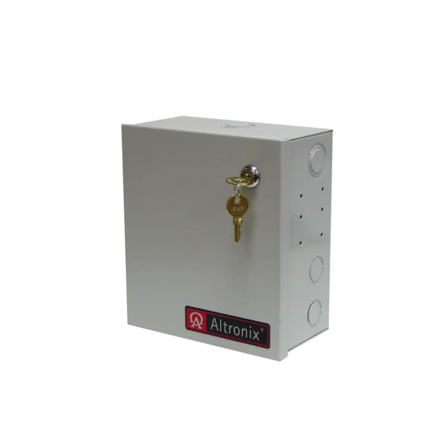
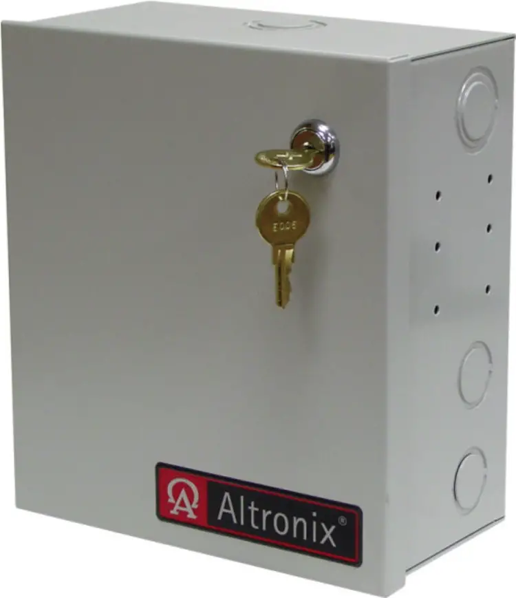
Altronix ALTV248ULCBMI CCTV Power Supply
Models Include
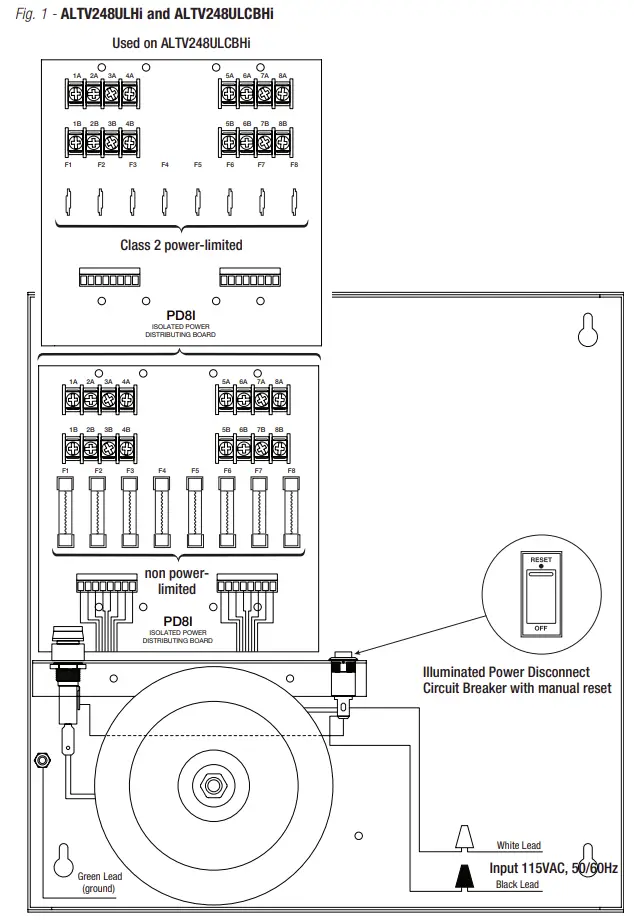
ALTV248ULHi
- 24VAC @ 12.5A total output.
- Eight (8) 1.56A Fuse Protected Isolated Outputs.
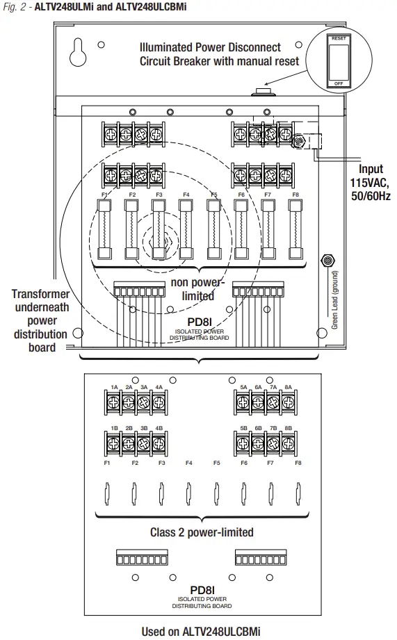
ALTV248ULMi
- 24VAC @ 12.5A total output.
- Eight (8) 1.56A Fuse Protected Isolated Outputs.
ALTV2416ULi
- 24VAC @ 25A total output.
- Sixteen (16) 1.56A Fuse Protected Isolated Outputs.
ALTV248ULCBHi
- 24VAC @ 12.5A total output.
- Eight (8) 1.56A PTC Protected Isolated Outputs.
ALTV248ULCBMi
- 24VAC @ 12.5A total output.
- Eight (8) 1.56A PTC Protected Isolated Outputs.
ALTV2416ULCBi
- 24VAC @ 25A total output.
- Sixteen (16) 1.56A PTC Protected Isolated Outputs.\
For models with factory installed 3-wire line cord add suffix “3” (e.g. ALTV248ULHi3).
Overview
Altronix Isolated CCTV Power Supplies provide 24VAC distributed via eight (8) or sixteen (16) fuse or PTC protected isolated outputs for powering CCTV cameras, heaters, and other video accessories.
Isolated Power Supply Reference Chart:
| Altronix Model Number | Output Voltage | Total Output Current | Number of Outputs | PTC Protected auto- resettable Outputs (Class 2 Power- Limited for dry locations) | Fuse Protected Outputs | Output Current (max per output) | 115VAC 50/60Hz Input Current | Agency Listing |
| ALTV248ULHi | 24VAC | 12.5A | 8 | – | P | 1.56A | 3A |
|
| ALTV248ULCBHi | 24VAC | 12.5A | 8 | P | – | 1.56A | 3A | |
| ALTV248ULMi | 24VAC | 12.5A | 8 | – | P | 1.56A | 3A | |
| ALTV248ULCBMi | 24VAC | 12.5A | 8 | P | – | 1.56A | 3A | |
| ALTV2416ULi | 24VAC | 25A | 16 | – | P | 1.56A | 6A | |
| ALTV2416ULCBi | 24VAC | 25A | 16 | P | – | 1.56A | 6A |

Add suffix “3” for 3-wire line cord (e.g. ALTV248ULHi3).
Specifications
Agency Listings:
- UL Listed for Commercial CCTV Equipment (UL2044).
CUL Listed – CSA Standard C22.2 No.1-98, Audio, Video and Similar Equipment.
Input:
- 115VAC, 50/60Hz.
Output:
- Eight (8) or sixteen (16) fuse or PTC protected outputs.
- 24VAC outputs.
- Outputs are rated @ 3.5A (fused) or 2.5A (PTC).
- Surge suppression.
Features:
- Individual electronically isolated outputs.
- Illuminated master Power ON/OFF switch with built-in circuit breaker.
- Unit maintains camera synchronization.
- Ease of installation saves time & eliminates costly labor.
- Spare fuses included (on fuse protected models).
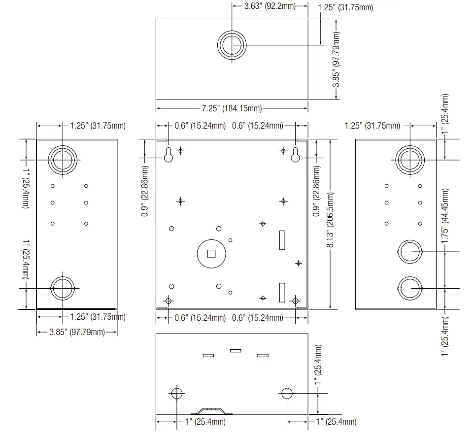
Enclosure Dimensions (H x W x D approx.):
ALTV248ULMi, ALTV248ULCBMi:
8.5” x 7.5” x 3.875” (215.9mm x 191mm x 98.4mm).
ALTV248ULHi, ALTV248ULCBHi,
ALTV2416ULi, and ALTV2416ULCBi:
13.5” x 13” x 3.25” (342.9mm x 330.2mm x 82.6mm).
Installation Instructions
Wiring methods shall be in accordance with the National Electrical Code/NFPA 70/NFPA 72/ANSI, and with all local codes and authorities having jurisdiction. Product is intended for indoor use only.
- Mount unit in the desired location. Mark and predrill holes in the wall to line up with the top two keyholes in the enclosure. Install two upper fasteners and screws in the wall with the screw heads protruding. Place the enclosure’s upper keyholes over the two upper screws, level and secure. Mark the position of the lower two holes. Remove the enclosure. Drill the lower holes and install the three fasteners. Place the enclosure’s upper keyholes over the two upper screws. Install the two lower screws and make sure to tighten all screws (Enclosure Dimensions, pg. 7, 8). Secure enclosure to earth ground.
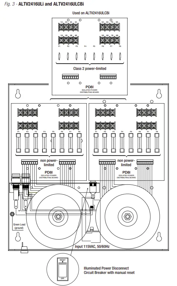
- Set power switch to OFF position on all models (Fig. 1 – 3, pg. 4 – 6).
- All units are factory set for 24VAC operation.
- Secure green lead to earth ground. Connect AC power to the black and white flying leads of the transformer(s) (Fig. 1 – 3, pg. 4 – 6). Use 18 AWG or larger for all power connections
Keep power-limited wiring (PTC protected outputs only) separate from non power-limited wiring. Minimum 0.25” spacing must be provided. Use separate knockouts - Measure output voltage before connecting devices. This helps avoiding potential damage. Terminals marked [1A – 8A] and [1B – 8B] are of the same polarity (phase).
- Connect CCTV cameras to output terminals using the following procedure:
Camera 1 to output 1A & 1B Camera 5 to output 5A & 5B Camera 2 to output 2A & 2B Camera 6 to output 6A & 6B Camera 3 to output 3A & 3B Camera 7 to output 7A & 7B. Camera 4 to output 4A & 4B. Camera 8 to output 8A & 8B. - Set power switch on all models to the “RESET” (ON) position (Fig. 1 – 3, pg. 4 – 6).
- Upon completion of the wiring, secure enclosure door with screws (supplied).
Caution: Equipment to be installed/serviced by authorized/trained personnel only. Shut branch circuit power before installing/servicing equipment.
WARNING: To reduce the risk of fire or electric shock, do not expose the unit to rain or moisture. This installation should be made by qualified service personnel and should conform to the National Electrical Code and all local codes. Use 75˚C or higher rated UL insulated wiring for connecting the unit to the mains. Replace fuses with the same type and rating (3.5A/250V).
Terminal Identification
PD8i – Distribution Module
| 1A – 8A | Phase 1 |
| 1B – 8B | Phase 2 |
 | The lightning flash with arrowhead symbol within an equilateral triangle is intended to alert the user to the presence of an insulated DANGEROUS VOLTAGE within the product’s enclosure that may be of sufficient magnitude to constitute an electric shock. |
 | The exclamation point within an equilateral triangle is intended to alert the user to the presence of important operating and maintenance (servicing) instructions in the literature accompanying the appliance. |
 | CAUTION: To reduce the risk of electric shock do not open enclosure. There are no user serviceable parts inside. Refer servicing to qualified service personnel. |
Dimensions
Enclosure Dimensions (H x W x D) for:
• ALTV248ULMi • ALTV248ULCBMi
8.5” x 7.5” x 3.875” (215.9mm x 191mm x 98.4mm)
Enclosure Dimensions (H x W x D) for:
• ALTV248ULHi • ALTV248ULCBHi
• ALTV2416ULi • ALTV2416ULCBi
13.5” x 13” x 3.25” (342.9mm x 330.2mm x 82.6mm)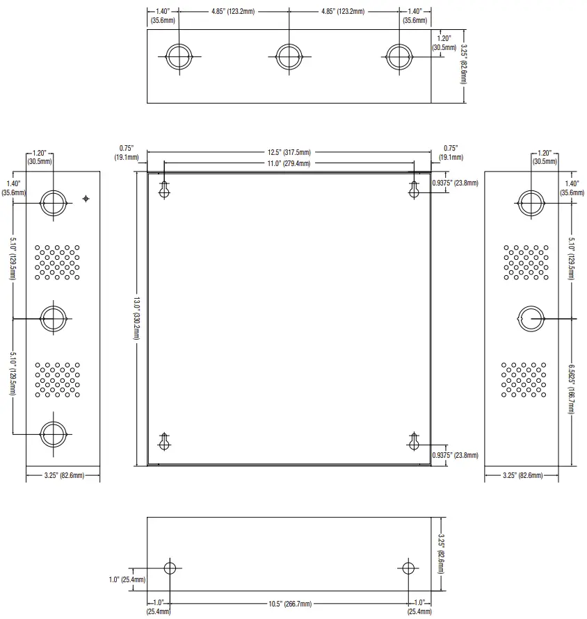
Altronix is not responsible for any typographical errors.
140 58th Street, Brooklyn, New York 11220 USA | phone: 718-567-8181 | fax: 718-567-9056
website: www.altronix.com | e-mail: [email protected] | Lifetime Warranty
IIULisolated Series