Altronix ALTV248 8Output CCTV Power Supplies
Overview
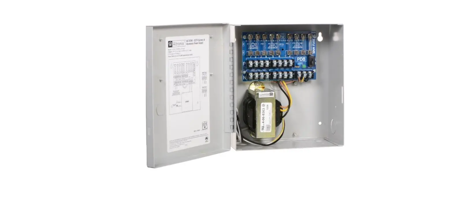
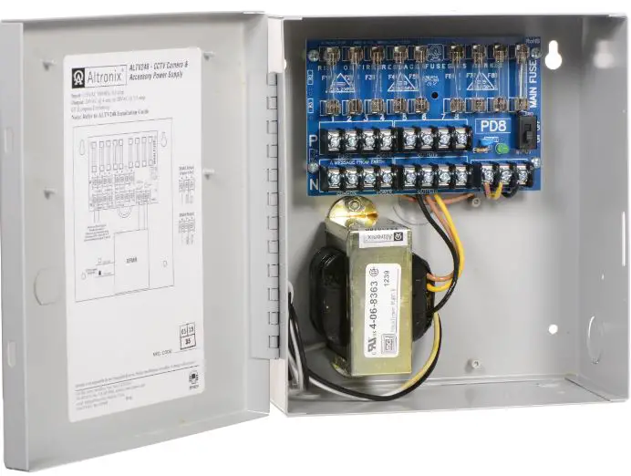
Altronix ALTV248 Series CCTV Power Supplies provide 24VAC or 28VAC distributed via eight (8) fuse or PTC protected outputs for powering CCTV cameras, heaters and other video accessories.
Eight (8) Output ALTV248 Reference Chart:
| Altronix Model Number | Output Voltage | Total Output Current (Power) | Number of Outputs | PTC Protected Auto Resettable Outputs | Fuse Protected Outputs | Output Current (max per output) | Main Fuse Ratings | 115VAC 50/60Hz Input Current |
| ALTV248 | 24VAC | 4A | 8 | – | P | 3.5A | 5A/250V | 0.9A |
| 28VAC | 3.5A | |||||||
| ALTV248CB | 24VAC | 4A | P | – | 2.5A | |||
| 28VAC | 3.5A | |||||||
| ALTV248175 | 24VAC | 7.25A | – | P | 3.5A | 10A/250V | 1.45A | |
| 28VAC | 6.25A | |||||||
| ALTV248175CB | 24VAC | 7.25A | P | – | 2.5A | |||
| 28VAC | 6.25A | |||||||
| ALTV248300 | 24VAC | 14A | – | P | 3.5A | 15A/32V | 2.7A | |
| 28VAC | 12.5A | |||||||
| ALTV248300CB | 24VAC | 14A | P | – | 2.5A | |||
| 28VAC | 12.5A | |||||||
| ALTV248600 | 24VAC | 28A | – | P | 3.5A | Two (2) 15A/32V | 5.4A | |
| 28VAC | 25A | |||||||
| ALTV248600CB | 24VAC | 28A | P | – | 2.5A | |||
| 28VAC | 25A |
Specifications:
Input:
- 115VAC, 50/60Hz.
Output:
- Eight (8) fuse or PTC protected outputs.
- 24VAC or 28VAC supply current.
- Outputs are rated @ 3.5A (fused) or 2.5A (PTC).
- Surge suppression.
Features:
- AC power LED.
- Power ON/OFF switch.
- Spare fuses provided. (all models w/primary and/or secondary fuses).
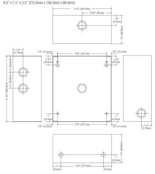
Enclosure Dimensions:
- ALTV248, ALTV248CB, ALTV248175 and ALTV248175CB:
8.5” x 7.5” x 3.5” (215.9mm x 190.5mm x 88.9mm). - ALTV248300 and ALTV248300CB:
12.25” x 7.25” x 4.5” (311.2mm x 184.2mm x 114.3mm). - ALTV248600 and ALTV248600CB:
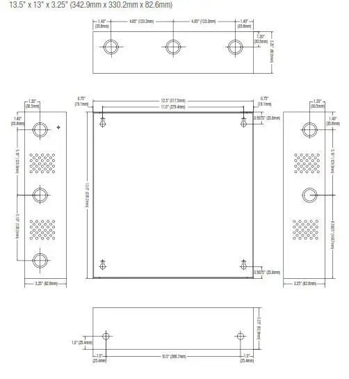
13.5” x 13” x 3.25” (342.9mm x 330.2mm x 82.6mm).
Installation Instructions:
- Mount unit in the desired location. Mark and predrill holes in the wall to line up with the top two keyholes in theenclosure. Install two upper fasteners and screws in the wall with the screw heads protruding. Place the enclosure’s upper keyholes over the two upper screws, level and secure. Mark the position of the lower two holes. Remove the enclosure. Drill the lower holes and install three fasteners. Place the enclosure’s upper keyholes over the two upper screws. Install the two lower screws and make sure to tighten all screws (Enclosure Dimensions, pg. 8-10). Secure enclosure to earth ground.
- Slide switch on PD board to the OFF position for models ALTV248 and ALTV248CB (Fig. 1, pg. 4). Turn OFF main switch on all other models, (Figs. 2-4 pgs. 5-7).
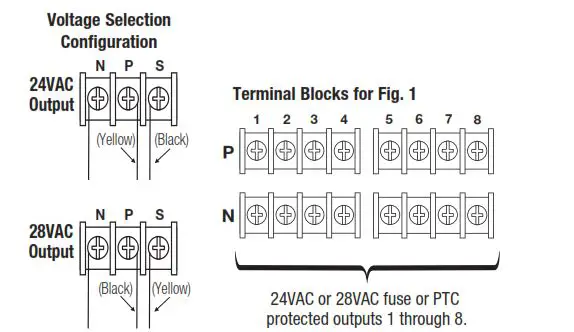
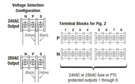
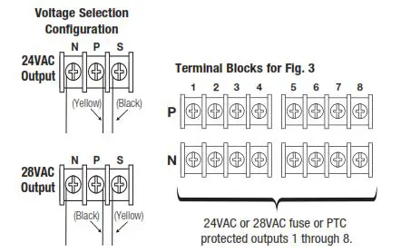
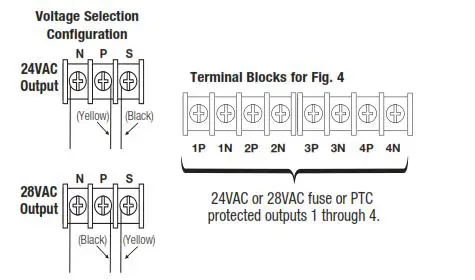
- All units are factory set for 24VAC operation. For 28VAC operation adjust unit prior to mounting and applying power as follows:
Change the wire position so that the black wire [28V] is connected to the terminal marked [P] and the yellow wire [24V] is connected to the terminal marked[S]. - Connect AC power to the black and white flying lead of the transformer(s) (Figs. 1-4, pgs. 4-7). Use 18 AWG or larger for all power connections.
- Measure output voltage before connecting devices. This helps avoiding potential damage. Terminals marked [1P – 8P] are positive of the same polarity.
CAUTION: Determine the maximum operating voltage of the equipment being powered before adjusting the output voltage. - Connect devices to the terminals marked [1P – 1N] through [4P – 4N] on PD4/PD4CB board (Fig. 4, pg. 7) or terminals marked [1P – 1N] through [8P – 8N] on PD8/PD8CB board (Figs. 1-3, pgs. 4-6), carefully observing polarity.
- Slide switch on PD board to the ON position for models ALTV248 and ALTV248CB (Fig. 1, pg. 4). Turn main switch on all other models to the “RESET” (ON) position (Figs. 2-4, pgs. 5-7).
- Green LED will illuminate when unit is powered.
- Upon completion of wiring, secure enclosure door with screws (supplied).
Caution: Equipment to be installed / serviced by authorized / trained personnel only. Shut branch circuit power before installing / servicing equipment.
WARNING: To reduce the risk of fire or electric shock, do not expose the unit to rain or moisture. This installation should be made by qualified service personnel and should conform to the National Electrical Code and all local codes.
Terminal Identification:
PD4/PD4CB – Distribution Module
| 1P – 4P | AC output. |
| 1N – 4N | AC output. |
PD8/PD8CB – Distribution Module
| 1P – 8P | AC output. |
| 1N – 8N | AC output. |
 :The lightning flash with arrowhead symbol within an equilateral triangle is intended to alert the user to the presence of an insulated DANGEROUS VOLTAGE within the product’s enclosure that may be of sufficient magnitude to constitute an electric shock.
 :The exclamation point within an equilateral triangle is intended to alert the user to the presence of important operating and maintenance (servicing) instructions in the literature accompanying the appliance.

CAUTION: To reduce the risk of electric shock do not open enclosure. There are no user serviceable parts inside. Refer servicing to qualified service personnel.
ALTV248 and ALTV248CB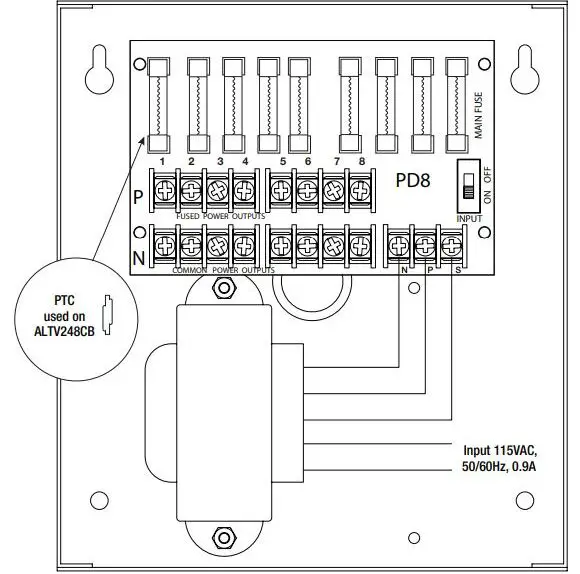
ALTV248175 and ALTV248175CB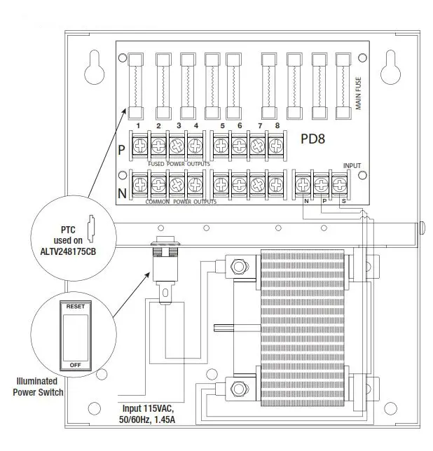
ALTV248300 and ALTV248300CB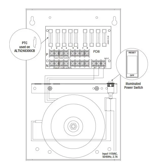
ALTV248600 and ALTV248600CB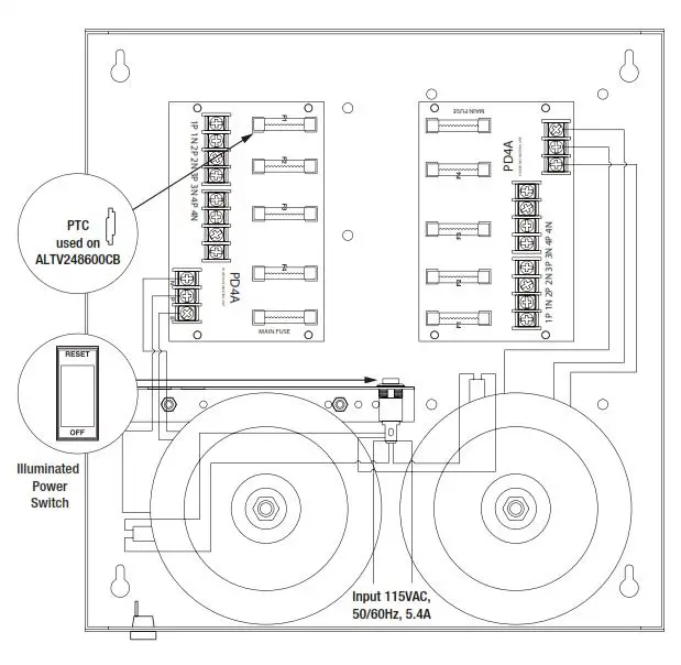
Enclosure Dimensions (H x W x D) for:
- ALTV248
- ALTV248CB
- ALTV248175
- ALTV248175CB

Enclosure Dimensions (H x W x D) for:
- ALTV248300
ALTV248300CB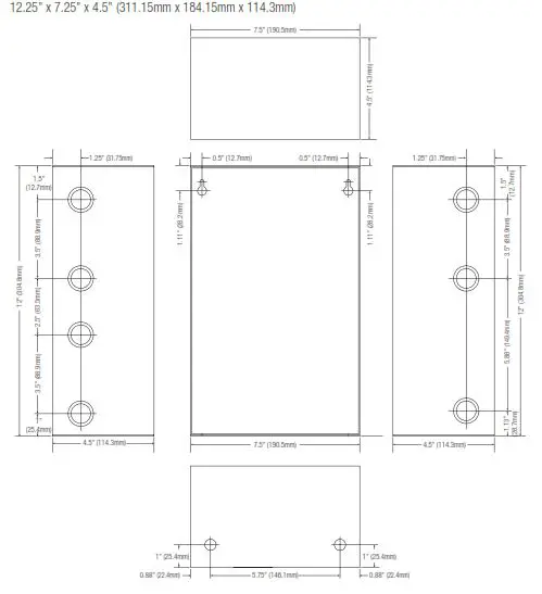
Enclosure Dimensions (H x W x D) for:
- ALTV248600
- ALTV248600CB