 ALTV2432 Series
32-Output CCTV Power Supplies
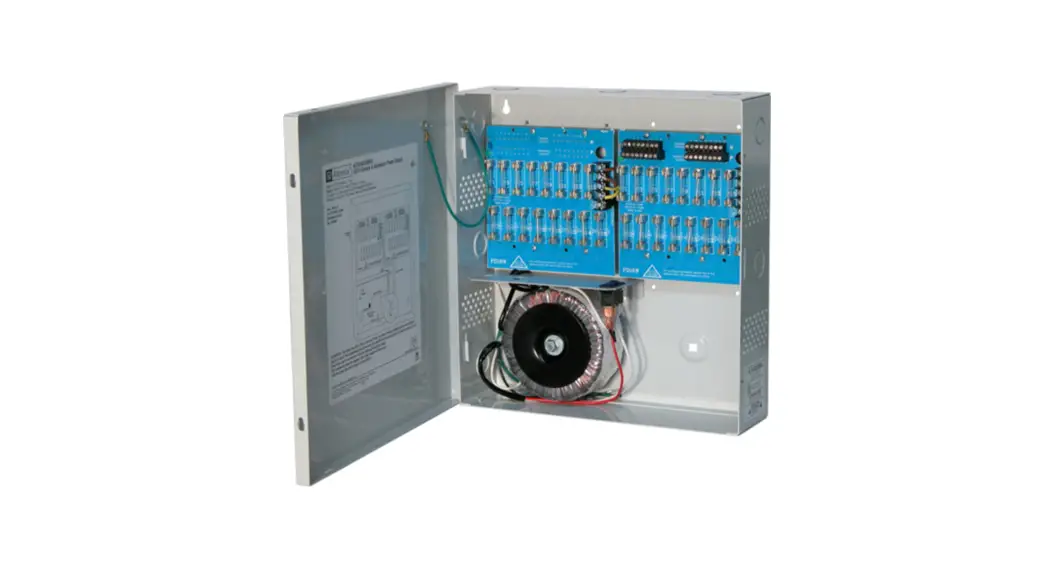
ALTV2432 32-Output CCTV Power Supplies
Models Include:
ALTV2432
– 24VAC @ 8A (200VA) or
28VAC @ 7A (200VA).
– Thirty-two (32) Fuse Protected Outputs.
ALTV2432350
– 24VAC @ 14A (350VA) or
28VAC @ 12.5A (350VA).
– Thirty-two (32) Fuse Protected Outputs.
ALTV2432600
– 24VAC @ 28A (700VA) or
28VAC @ 25A (700VA).
– Thirty-two (32) Fuse Protected Outputs.
ALTV2432CB
– 24VAC @ 8A (100VA) or
28VAC @ 7A (200VA).
– Thirty-two (32) PTC Protected Outputs.
ALTV2432350CB
– 24VAC @ 14A (350VA) or
28VAC @ 12.5A (350VA).
– Thirty-two (32) PTC Protected Outputs.
ALTV2432600CB
– 24VAC @ 28A (700VA) or
28VAC @ 25A (700VA).
– Thirty-two (32) PTC Protected Outputs.
Installation Guide
 Rev. 021704
Installing Company: _______________ Service Rep. Name: ________________
Address: _______________________ Phone #: __________________
Overview:
Altronix ALTV2432 Series CCTV Power Supplies provide 24VAC or 28VAC distributed via thirty-two (32) fuse or PTC-protected outputs for powering CCTV cameras, heaters, and other video accessories.
Thirty-Two (32) Output ALTV2432 Reference Chart:
| Altronix Model Number | Output Voltage | Total Output Current (Power) | Number of Outputs | PTC Protected Outputs (auto-resettable) i | Fuse Protected Outputs | Output Current (max per output) | Main Fuse Ratings | 115VAC 50/60Hz Input Current |
| ALTV2432 | 24VAC | A | 32 | – | ✓ | 3.5A | 5N 250V | 2.9A |
| 28VAC | 7q A | |||||||
| ALTV2432CB | 24VAC | 8A | ✓ | – | 2.5A | |||
| 28VAC | 7A | |||||||
| ALTV2432350 | 24VAC | 14A | — | ✓ | 3.5A | 10A/ 250V | 2.7A | |
| 28VAC | 12.5A | |||||||
| ALTV2432350CB | 24VAC | 14A | v | – | 2.5A | |||
| 28VAC | 12.5A | |||||||
| ALTV2432600 | 24VAC | 28A | — | ✓ | 3.5A | 15W 32V | 5.4A | |
| 28VAC | 25A | |||||||
| ALTV2432600CB | 24VAC | 28A | ✓ | – | 2.5A | |||
| 28VAC | 25A |
Specifications:
Input:
- 115VAC, 50/60Hz.
Output:
- Thirty-two (32) fuse or PTC-protected outputs.
- 24VAC or 28VAC supply current.
- Outputs are rated @ 3.5A (fused) or 2.5A (PTC).
- Surge suppression.
Features:
- Secondary fuse rated @ 10A/250V.
- AC power LED.
- Power ON/OFF switch.
- Spare fuses provided.
(all models w/primary and/or secondary fuses).
Enclosure Dimensions:
13.5” x 13” x 3.25”
(342.9mm x 330.2mm x 82.6mm).
Installation Instructions:
- Mount the unit in the desired location. Mark and predrill holes in the wall to line up with the top two keyholes in the enclosure. Install two upper fasteners and screws in the wall with the screw heads protruding. Place the enclosure’s upper keyholes over the two upper screws; level and secure. Mark the position of the lower two holes. Remove the enclosure. Drill the lower holes and install the fasteners. Place the enclosure’s upper keyholes over the two upper screws. Install the two lower screws and make sure to tighten all screws (Enclosure Dimensions, pg. 8). Secure the enclosure to earth ground.
- Turn the main switch on the unit OFF (Fig. 1-3, pgs. 4-6).
- All units are factory set for 24VAC operation.
For 28VAC operation, adjust the unit prior to mounting and applying power as follows: Change the wire position so that the black wire [28V] is connected to the terminal marked [P] and the yellow wire [24V] is connected to the terminal marked [S]. - Connect AC power to the black and white flying leads of the transformer(s) (Figs. 1-3, pgs. 4-6), and secure green lead to earth ground. Use 18 AWG or larger for all power connections.
- Measure output voltage before connecting devices. This helps avoid potential damage.
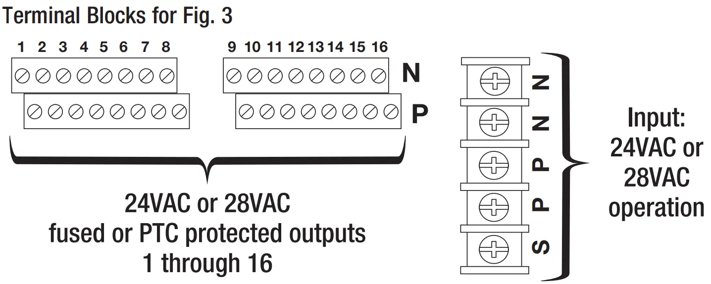
CAUTION: Determine the maximum operating voltage of the equipment being powered before adjusting the output voltage. - Connect devices to the terminals marked [1P – 1N] through [16P – 16N] on PD16W/PD16WCB board (Figs. 1-3, pgs. 4-6), carefully observing polarity. Terminals marked [1P – 16P] are of the same polarity.
- Turn the main switch on the unit to the ON (RESET) position (Figs. 1-3, pgs. 4-6).
- Green LED(s) will illuminate when the unit is powered.
- Upon completion of the wiring secure the enclosure door with screws (supplied).
Caution: Equipment to be installed/serviced by authorized/trained personnel only.
Shut branch circuit power before installing/servicing equipment.
warning: To reduce the risk of fire or electric shock, do not expose the unit to rain or moisture.
This installation should be made by qualified service personnel and should conform to the National Electrical Code and all local codes.
Terminal Identification:
PD16W/PD16WCB – Distribution Module
| 1P – 16P | AC output. |
| 1N – 16N | AC output. |
![]() The lightning flash with an arrowhead symbol within an equilateral triangle is intended to alert the user to the presence of an insulated DANGEROUS VOLTAGE within the product’s enclosure that may be of sufficient magnitude to constitute an electric shock.
The lightning flash with an arrowhead symbol within an equilateral triangle is intended to alert the user to the presence of an insulated DANGEROUS VOLTAGE within the product’s enclosure that may be of sufficient magnitude to constitute an electric shock.![]() The exclamation point within an equilateral triangle is intended to alert the user to the presence of important operating and maintenance (servicing) instructions in the literature accompanying the appliance.
The exclamation point within an equilateral triangle is intended to alert the user to the presence of important operating and maintenance (servicing) instructions in the literature accompanying the appliance.![]()
![]()
![]() CAUTION: To reduce the risk of electric shock do not open the enclosure.
CAUTION: To reduce the risk of electric shock do not open the enclosure.
There are no user-serviceable parts inside.
Refer servicing to qualified service personnel.
Fig. 1 – ALTV2432 and ALTV2432CB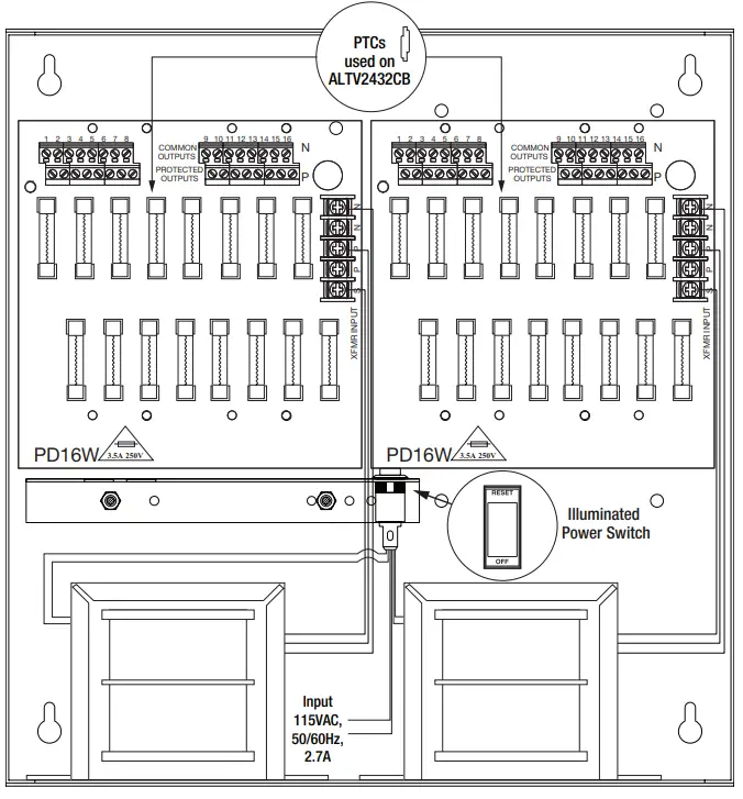
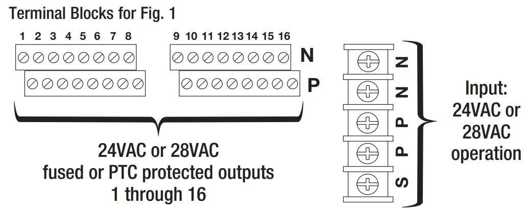
Fig. 2 – ALTV2432350 and ALTV2432350CB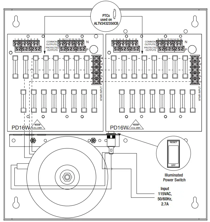
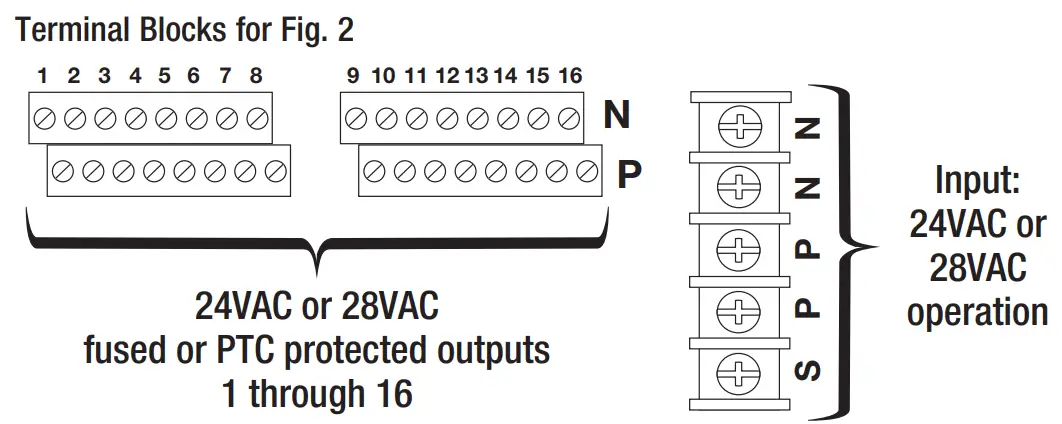
Fig. 3 – ALTV2432600 and ALTV2432600CB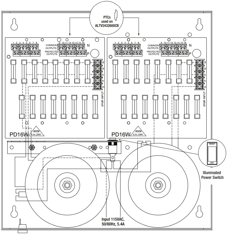
Enclosure Dimensions (H x W x D):
13.5” x 13” x 3.25” (342.9mm x 330.2mm x 82.6mm)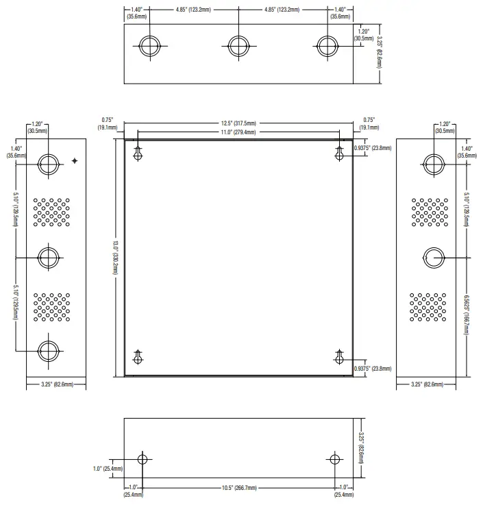
 ALTV2432 Series Installation Guide
Altronix is not responsible for any typographical errors.
140 58th Street, Brooklyn, New York 11220 USA
718-567-8181
fax: 718-567-9056
website: www.altronix.com
e-mail: [email protected]
Lifetime Warranty
IIALTV2432 Series J27U


