![]() Red Fox 7528 Series Industrial Routing Switches
Red Fox 7528 Series Industrial Routing Switches
User Guide
General Information
1.1. Legal Information
The contents of this document are provided “as is”. Except as required by applicable law, no warranties of any kind are made in relation to the accuracy and reliability or contents of this document, either expressed or implied, including but not limited to the implied warranties of merchantability and fitness for a particular purpose. Westeros reserves the right to revise this document or withdraw it at any time without prior notice.
Under no circumstances shall Westeros be responsible for any loss of data or income or any special, incidental, and consequential or indirect damages howsoever caused.
More information about Westeros can be found at www.westermo.com
1.2. About This Guide
This guide is intended for installation engineers and users of the Westeros products.
It includes information on safety and regulations, a product description, installation instructions and technical specifications.
1.3. Software Tools
Related software tools are available at https://www.westermo.com/support/productsupport.
1.4. License and Copyright for Included FLOSS
This product includes software developed by third parties, including Free/Libre Open Source Software (FLOSS). The specific license terms and copyright associated with the software are included in each software package respectively. Please visit the product web page for more information.
Upon request, the applicable source code will be provided. A nominal fee may be charged to cover shipping and media. Please direct any source code request to your normal sales or support channel.
1.5. Woe’s
This product runs Woe’s 5 (Westeros Operating System). Instructions for quick start, configuration and factory reset are found in the Woe’s user documentation at www.westermo.com.
Safety and Regulations
2.1. Warning Levels
Warning signs are provided to prevent personal injuries and/or damages to the product. The following levels are used:
| Level of warning | Description | Consequence personal injury | Consequence material damage |
| Indicates a potentially hazardous situation | Possible death or major injury | Major damage to the product |
| Indicates a potentially hazardous situation | Minor or moderate injury | Moderate damage to the product |
| Provides information in order to avoid misuse of the product, confusion or misunderstanding | No personal injury | Minor damage to the product |
| Used for highlighting general, but important information | No personal injury | Minor damage to the product |
able 1. Warning levels
2.2. Safety Information
Before installation:
Read this manual completely and gather all information available on the product. Make sure it is fully understood. Check that your application does not exceed the safe operating specifications for the product.
![]() SAFETY DURING INSTALLATION
SAFETY DURING INSTALLATION
The product must be installed and operated by qualified service personnel and installed into an apparatus cabinet or similar, where access is restricted to service personnel only.
Refer to chapter Compliance Information to see the required level of qualified service personnel according to safety standards.
Before energizing and connecting communication cables to the product, ensure a protective earthing conductor is first connected to the protective earthing terminal (only valid for metallic housings). Westeros recommends a cross-sectional area of at least 4 mm
Upon removal of the product, disconnect the product from the power supply and all other communication ports before disconnecting the protective earthing conductor.
![]() HAZARDOUS VOLTAGE
HAZARDOUS VOLTAGE
Do not open an energized product. Hazardous voltage may occur when connected to a power supply.
![]() PROTECTIVE FUSE
PROTECTIVE FUSE
The power supply wiring must be sufficiently fused.
It must be possible to disconnect manually from the power supply. Ensure compliance to national installation regulations.![]() POWER SUPPLY CONNECTION
POWER SUPPLY CONNECTION
There are safety regulations governing the power source that can be used in conjunction with the product. Refer to chapter Interface Specifications.
REDUCE THE RISK OF FIRE
To reduce the risk of fire, use only telecommunication line cords with a cable diameter of AWG 26 or larger. Regarding power cable dimensions, see chapter Interface Specifications.
![]() CLASS 1 LASER PRODUCT
CLASS 1 LASER PRODUCT
Do not look directly into a fiber optical port or any connected fiber, although the product is designed to meet the Class 1 Laser regulations and complies with 21 CFR 1040.10 and 1040.11.![]() HANDLING OF SFP TRANSCEIVERS SFP
HANDLING OF SFP TRANSCEIVERS SFP
transceivers are supplied with plugs to avoid contamination inside the optical port. They are very sensitive to dust and dirt. If the fiber optic cable is disconnected from the product, a protective plug must be used on the transmitter/receiver. The protective plug must be kept on during transportation. The fiber optic cable must be handled the same way.
![]() CORROSIVE GASES
CORROSIVE GASES
If the product is placed in a corrosive environment, it is important that all unused connector sockets are protected with a suitable plug, in order to avoid corrosion attacks on the gold plated connector pins.
![]() ELECTROSTATIC DISCHARGE (ESD)
ELECTROSTATIC DISCHARGE (ESD)
Prevent electrostatic discharge damage to internal electronic parts by discharging your body to a grounding point (e.g. use a wrist strap).
2.3. Care Recommendations
Follow the care recommendations below to maintain full operation of the product and to fulfill the warranty obligations:
- Do not drop, knock or shake the product. Rough handling above the specification may cause damage to internal circuit boards.
- Use a dry or slightly water-damp cloth to clean the product. Do not use harsh chemicals, cleaning solvents or strong detergents.
- Do not paint the product. Paint can clog the product and prevent proper operation.
If the product is used in a manner not according to specification, the protection provided by the equipment may be impaired.
If the product is not working properly, contact the place of purchase, the nearest Westeros distributor office or Westeros technical support.
2.4. Product Disposal
This symbol means that the product shall not be treated as unsorted municipal waste when disposing of it. It needs to be handed over to an applicable collection point for recycling electrical and electronic equipment.
By ensuring the product is disposed of correctly, you will help to reduce hazardous substances and prevent potential negative consequences to both the environment and human health, which could be caused by inappropriate disposal.![]() Figure 1. WEEE symbol for treatment of product disposal
Figure 1. WEEE symbol for treatment of product disposal
2.5. Compliance Information
2.5.1. Agency Approvals and Standards Compliance
| Type | Approval/Compliance |
| EMC | • EN/IEC 61000-6-2, Immunity industrial environments • EN/IEC 61000-6-4, Emission industrial environments • FCC Part 15.105 class A |
| Trackside | • EN 50121-4/IEC 62236-4, Railway signaling and telecommunications apparatus |
| Safety | • EN/IEC/UL 62368-1, Safety Requirements for audio/video, information and communication technology equipment |
2.5.2. FCC Part 15.105 Class A Notice
This product has been tested and found to comply with the limits for a Class A digital device, pursuant to Part 15 of the FCC Rules.
These limits are designed to provide reasonable protection against harmful interference when the product is operated in a commercial environment.
This product generates, uses, and can radiate radio frequency energy and, if not installed and used in accordance with the user manual, may cause harmful interference to radio communications. Operation of this product in a residential area is likely to cause harmful interference in which case the user will be required to correct the interference at the users own expense.
2.5.3. EN/IEC/UL 62368-1 Notice
This product has been tested and found compliant to EN/IEC/UL 62368-1, Safety for Communication Technology. In accordance with the definitions of the standard, this product shall be handled by instructed personnel. Energy source classifications are according to following:
2.5.4. Corrosive Environment
This product has been successfully tested in a corrosion test according to IEC 60068-2-60, method 3. This means that the product meets the requirements to be placed in an environment classified as ISA-S71.04 class G3.
![]() CORROSIVE GASES
CORROSIVE GASES
If the product is placed in a corrosive environment, it is important that all unused connector sockets are protected with a suitable plug, in order to avoid corrosion attacks on the gold plated connector pins.
2.5.5. Simplified Declaration of Conformity
Hereby, Westeros declares that this product is in compliance with applicable EU directives and UK legislations. The full declaration of conformity and other detailed information is available at www.westermo.com/support/product-support.![]() Figure 2. The European Conformity and the UK Conformity Assessment markings
Figure 2. The European Conformity and the UK Conformity Assessment markings
Product Description
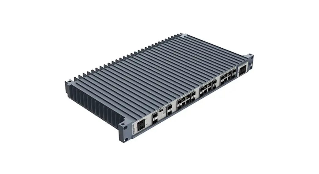
3.1. Product Description The RedFox-7528 Industrial Ethernet switch is designed to be a workhorse, providing performance and robustness today and for years to come. In today’s world, many applications combine data, voice, and video, and as a result, high performance and reliability are required. The RedFox-7528 high performance industrial Ethernet switches provide an ideal solution for these large-scale industrial networks.
RedFox-7528 is designed for 19” cabinets according to the ETSI standard, which makes it suitable for use in control room networks as well as for cabinets installed along railway trackside installations. In addition to the ultra-rugged IP40 finless all metal housing, it is equipped with configurable I/O fault contacts, which makes it ideal for easy installation and monitoring in industrial applications.
To ensure long service life and market leading MTBF, only industrial grade components are used. In addition, the switches can withstand constant vibration, extreme temperatures and demanding electrical environments. RedFox-7528 has been tested both by Westeros and external test labs to meet many standards regarding EMC, isolation, vibration and shock, all to the highest levels suitable for heavy industrial environments and rail trackside applications.
Powered by Woe’s, the Westeros network operating system, the switches are flexible, feature-rich as well as easy to install and configure. Woe’s has been developed to allow cross-platform and future-proof solutions and can deliver resilient and flexible networks, e.g. the FRNT ring protocol with very fast failover.
Ensuring the security of industrial data communication networks is of paramount importance, especially with the nature of cyberattacks becoming increasingly sophisticated. To reduce risk and increase cyberresilience, RedFox-7528 has an extensive suite of advanced cybersecurity features. These can be used to build networks in compliance with the IEC 62443 standard, which defines technical security requirements for data communication network components.
3.2. Available Models
| Art. no. | Model | No. of copper ports | No. of SFP ports | No. of SFP+ ports | Layer |
| 3641-4540 | RedFox-7528-F4G10F12G-T12G-LV | 12 | 12 | 4 | Layer 2 |
3.3. Hardware Overview
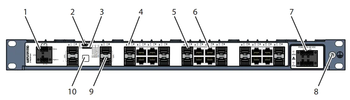
| No. | Description | No. | Description |
| 1 | I/O connection | 2 | Console port |
| 3 | Micro SD | 4 | LED indicators |
| 5 | 100/1000 Mbit/s SFP ports | 6 | 10/100/1000 Mbit/s TX ports |
| 7 | Power input | 8 | Protective earth |
| 9 | SFP+ ports | 10 | Label with data matrix. |
a. The base MAC address and production date of the product is included in the front label data matrix.
Figure 3. Location of interface ports and LED indicators
3.4. Connector Information
3.4.1. Power Input
| Illustration | Product marking | Direction | Description |
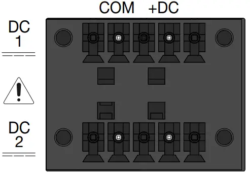 | +DC1 | Input | Supply voltage |
| +DC2 | Input | Supply voltage | |
| -COM | Input | Common | |
| -COM | Input | Common |
Table 2. Power input LV models
3.4.2. I/O Connection
| Illustration | Position | Product marking | Direction | Description |
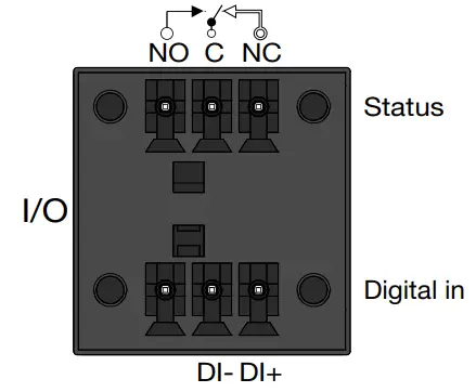 | Digital in | DI+ | Input | Digital in+ |
| DI- | Digital in- | |||
| Status | Status NO | Output | Alarm (status) relay contact NO – Normally Open C – Common NC – Normally Closed | |
| Status C | ||||
| Status NC |
Table 3. I/O connection
The Digital in is an opto-isolated digital input, which can be used to monitor external events.
The Status output is a potential free, opto-isolated, alternation (Form-C) solid-state relay.
This can be configured to monitor various alarm events within the product, see Woe’s Management Guide. An external load in series with an external DC voltage source is required for proper functionality.
| Unit condition | Status NO- C | Status NC-C |
| Unpowered / pre-operational or Alarm active | OPEN | CLOSED |
| Operational and Alarm inactive | CLOSED | OPEN |
Table 4. Status output
3.4.3. Console Port
The console port can be used to connect to the CLI (Command Line Interface). The console connector is a USB cable that connects to a FTDI FT232R USB to serial converter internally. For drivers, refer to www.ftdichip.com and download the appropriate VCP driver.
3.4.4. Micro SD
To insert the micro SD card correctly, turn the gold plated pins upwards.
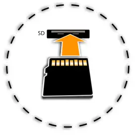 Figure 4. Insertion of micro SD card
3.4.5. SFP Transceivers
The product supports UL and IEC certified transceivers only. See Westeros’s modular transceivers datasheets for supported SFP and SFP+ transceivers, which can be downloaded from the product support pages at www.westermo.com/support/productsupport.
Each SFP slot can hold one SFP transceiver. See “Transceiver User Guide 6100-0000” for transceiver handling instructions, which also can be downloaded from the product support pages at
www.westermo.com/support/product-support.
In the event of contamination, the optical connectors in the SFP transceivers should only be cleaned by the use of forced nitrogen and some kind of cleaning stick. Recommended cleaning fluids are methyl-, ethyl-, isopropyl- or isobutyl alcohol, hexane or naphtha.
HANDLING OF SFP TRANSCEIVERS![]() SFP transceivers are supplied with plugs to avoid contamination inside the optical port. They are very sensitive to dust and dirt. If the fiber optic cable is disconnected from the product, a protective plug must be used on the transmitter/receiver. The protective plug must be kept on during transportation. The fiber optic cable must be handled the same way.
SFP transceivers are supplied with plugs to avoid contamination inside the optical port. They are very sensitive to dust and dirt. If the fiber optic cable is disconnected from the product, a protective plug must be used on the transmitter/receiver. The protective plug must be kept on during transportation. The fiber optic cable must be handled the same way.
3.5. LED Indicators
| LED | Status | Description |
| ON | OFF | Product has no power |
| GREEN | All OK, no alarm condition | |
| RED | Alarm condition, or until product has started up. (Alarm conditions are configurable, see WeOS5 User Guide) | |
| RSTP/ USR1 | OFF | RSTP disabled |
| GREEN | RSTP enabled | |
| BLINK | Product selected as RSTP/STP root switch | |
| USR1 | Configurable, see WeOS5 User Guide | |
| FRNT | OFF | FRNT disabled |
| GREEN | FRNT OK | |
| RED | FRNT error | |
| FLASH | Product configured as FRNT focal point | |
| DC1 | OFF | Product has no power |
| GREEN | Power OK on DC1 | |
| RED | Input voltage is below operating voltage limit | |
| DC2 | OFF | Product has no power |
| GREEN | Power OK on DC2 | |
| RED | Input voltage is below operating voltage limit | |
| USR2 | Configurable, see WeOS5 User Guide | |
| TX/FX ports | OFF | No link |
| GREEN | Link established | |
| GREEN FLASH | Data traffic indication | |
| YELLOW | Port alarm and no link. Or if FRNT or RSTP mode, port is blocked. | |
Table 5. LED indicators
3.6. Dimensions
Dimensions are stated in mm.
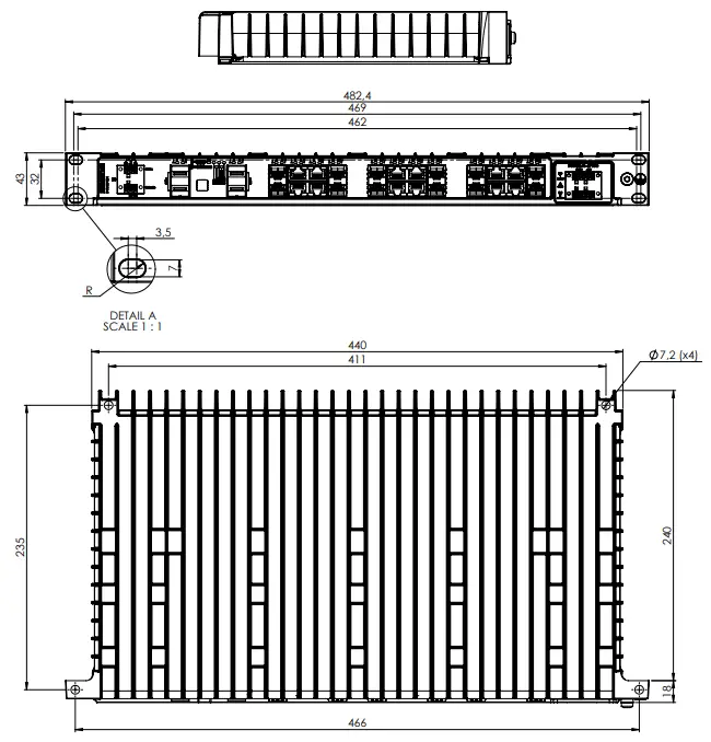
Figure 5. Dimensional drawing, illustrated by a RedFox-7528-F4G10-F12G-T12G-LV
Mounting
Redox is designed for installation in 19″ rack solutions according to ETSI standard, with a shallow depth of 240 millimeters. It can also be wall mounted as an installation option.
4.1. Rack Mounting
The product can be mounted in all directions inside a 19″ apparatus cabinet. Use supplied M6x25 (Philips no. 3) or 1/4×1″ screws.
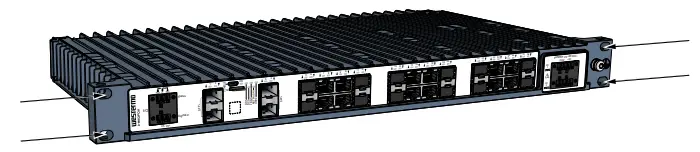
Figure 6. Rack mounted product
4.2. Wall Mounting
The product can be wall mounted in all directions. Use maximum 6.4 mm or 1/4″ screws.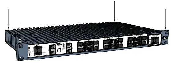
Figure 7. Wall mounted product
4.3. Protective Earth Connection
For correct function, the earth connection needs to be properly connected to a designated PE rail. Torn: T25 and torque: 3.2 Nm.
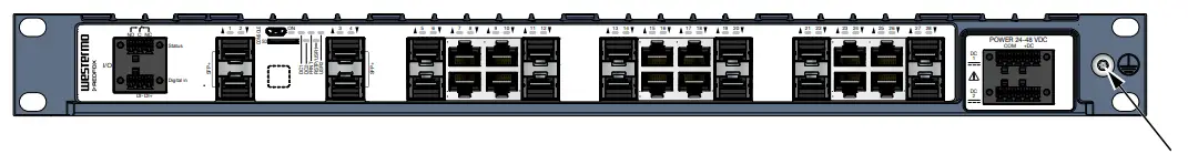
Figure 8. Earth connection
4.4. Cooling
This product relies on convection cooling. To avoid obstruction of the airflow around the product, follow the spacing recommendations.
For mounting in 19″ apparatus cabinet without forced ventilation, a minimal spacing of 1U according to IEC 60297 or 45 mm (1.75″) above/below is recommended.
For wall mounting in an area without forced ventilation, a minimum spacing of 45 mm (1.75″) above/below and 10 mm (0.4″) left/right is recommended.
Specifications
5.1. Interface Specifications
| Power port | ||
| Rated voltage | 24-48 VDC | |
| Operating voltage | 18-60 VDC | |
| Rated current | RedFox-7528-F4G10-F12G-T12G-LV | 1.39 A at 24 VDC 0.68 A at 48 VDC |
| Fuse rating Component: U2 | 4A(T), 125 VDC, breaking capacity 100 A, UL248-14 | |
| Rated frequency | DC | |
| Inrush current, I²ta. | 75 mA2s at 24 VDC 365 mA2s at 48 VDC | |
| Startup current | 2x nominal current | |
| Polarity | Reverse polarity protected | |
| Redundant power input | Yes | |
| Isolation | All other ports | |
| Connector | Detachable screw terminal | |
| Conductor cross section | 0.5-1.5 mm² (AWG 20-16) Use copper conductors only. | |
| Stripping length cable | 7 mm | |
| Cable temperature rating | Minimum temperature rating of the cable to be connected to the field wiring terminals is +77 °C | |
| Tightening torque, terminal screw | 0.34 Nm | |
| Tightening torque, screw flange | 0.34 Nm | |
| Shielded cable | Not required | |
a. Measured for 1 second at startup
| I/O connection, Digital input | |
| Isolation to | All other ports |
| Connector | Detachable screw terminal |
| Conductor cross section | 0.08 – 1.5 mm² (AWG 28-16). Use copper conductors only. |
| Stripping length cable | 7 mm |
| Cable temperature rating | Minimum temperature rating of the cable to be connected to the field wiring terminals is +77 °C |
| Tightening torque, terminal screw | 0.22 – 0.25 Nm |
| Terminal torque, screw flange | 0.3 Nm |
| Circuit type | SELV |
| Maximum voltage/current | 60 VDC, IIN ≤ 2.9 mA at 60 VDC |
| Voltage levels | Logic one: >8 VDC Logic zero: <5 VDC |
| I/O connection, Relay output | |
| Connect resistance | Maximum 30 Ω |
| Isolation to | All other ports |
| Connector | Detachable screw terminal |
| Conductor cross section | 0.08 – 1.5 mm² (AWG 28-16). Use copper conductors only. |
| Stripping length cable | 7 mm |
| Cable temperature rating | Minimum temperature rating of the cable to be connected to the field wiring terminals is +77 °C |
| Tightening torque, terminal screw | 0.22 – 0.25 Nm |
| Terminal torque, screw flange | 0.3 Nm |
| Circuit type | SELV |
| Type of switch | Solid state, DC general use, DC Pilot duty |
| Maximum withstand across open contacts | 60 VDC (continuous) |
| Permissible current | 80 mA (continuous), 120 mA (short term 1 s.) |
| Ethernet TXa. | |
| Electrical specification | IEEE sty 802.3 |
| Data rate | 10 Mbit/s, 100 Mbit/s, 1000 Mbit/s, manual or auto |
| Duplex | Full or half, manual or auto |
| Circuit type | TNV-1 |
| Transmission range | Up to 100 m with CAT5e cable or better |
| Isolation | All other ports |
| Cabling | Shielded cable CAT5e or better is recommended |
| Conductive chassis | Yes |
a.10/100/1000 Mbit/s ports are: 7-10, 15-18, 23-26
| SFP ports. | |
| Optical/Electrical specification | IEEE sty 802.3 |
| Data rate | 100 Mbit/s, 1000 Mbit/sb. |
| Duplex | Full or half, manual or auto |
| Transmission range | Depending on transceiver |
| Connector | SFP slot holding fiber transceiver |
a. SFP ports are: 5-6, 11-14, 19-22, 27-28
b.100 Mbit/s or 1000 Mbit/s transceiver supported
| SFP+ ports. | |
| Optical/Electrical specification | IEEE sty 802.3 |
| Data rate | 1000 Mbit/s, 10 Grit/sb. |
| Duplex | Full or half, manual or auto |
| Transmission range | Depending on transceiver |
| Connector | SFP+ slot holding fiber transceiver |
a. SFP+ ports are: 1-4
b.1000 Mbit/s or 10 Grit/s transceiver supported
| Console port | |
| Electrical specification | USB 2.0 device interface |
| Data rate | Up to 480 MPs (high-speed mode) |
| Circuit type | SELV |
| Maximum supply current | 100 mA |
| Connector | USB Micro B connector in device mode |
| Micro SD | |
| Electrical specification | Secure Digital 2.0 |
| Circuit type | SELV |
| Maximum supply current | 100 mA |
| Connector | Micro SD connector |
5.1. Type Tests and Environmental Conditions
| Environmental phenomena | Basic standard | Description | Test levels |
| ESD | EN 61000-4-2 | Enclosure | Contact: ±6 kV Air: ±8 kV |
| Fast transients | EN 61000-4-4 | Power port I/O ports Earth port | ± 2 kV, 5 kHz, 100 kHz |
| Surge 1.2/50 µs | EN 61000-4-5 | Power port | L-E: ± 1 kV, 12 Ω, 9 µF L-E: ± 2 kV, 42 Ω, 0,5 µF L-L: ± 0,5 kV, 2 Ω, 18 µF L-L: ± 1 kV, 42 Ω, 0,5 µF |
| I/O ports | L-E: ± 2 kV, 42 Ω, 0.5 µF L-L: ± 1 kV, 42 Ω, 0.5 µF | ||
| Ethernet ports | L-E: ± 2 kV, 2 Ω direct on shield | ||
| Power frequency magnetic field | EN 61000-4-8 | Enclosure | 100 A/m, 16.7, 50 and 60 Hz 300 A/m DC |
| Pulsed magnetic field | EN 61000-4-9 | Enclosure | 300 A/m |
| Radiated RF immunity | EN 61000-4-3 | Enclosure | 20 V/m at (80 MHz to 2.7 GHz) 10 V/m at (2.7 to 6 GHz) |
| Conducted RF immunity | EN 61000-4-6 | Power port Ethernet ports I/O ports Earth port | 10 V, 80% AM, 1 kHz; (0.15-80) MHz |
| Radiated RF emission | CISPR 16-2-3 | Enclosure | Class A, (30-6000 MHz) |
| ANSI C63.4 | Class A (FCC Part 15 B, 30 MHz to 26 GHz) | ||
| Conducted RF emission | CISPR 16-2-1 | Power port | Class A |
| ANSI C63.4 | Class A, (FCC Part 15 B) | ||
| CISPR 22 | Ethernet ports | Class A | |
| Dielectric strength | EN/IEC/UL 62368-1 | Power-, I/O- and Ethernet-ports to all other ports, incl. chassis | 1500 VAC rams, 60 s |
| IEEE 802.3 | Ethernet-ports to all other ports, incl. chassis | 1500 VAC rams, 60 s |
Table 6. EMC and electrical conditions
| Environmental phenomena | Basic standard | Description | Test levels |
| Temperatures | EN 60068-2-1 EN 60068-2-2 | Operational | -40 to +70 °C (-40 to +158 °F)a. |
| Storage and transport | -40 to +85°C (-40 to +185°F) | ||
| Humidity | EN 60068-2-30 | Damp heat, cyclic | +25 to 55°C, 95% RH 2 cycles (12+12 hours) = 48 hours |
| Corrosive gases | IEC 60068-2-60 | Operating | Method 3, 21 days. |
| Altitude | Operational | 2000 m/80 kPa | |
| MTBF hours | MIL-HDBK 217F | 371,000 hours | |
| Telcordia | 763,000 hours | ||
| Vibration | IEC 60068-2-6 (sine) | Operational | 5 – 8 Hz: ±7.5 mm 8 – 500 Hz: 2 g 5 sweeps per axis |
| IEC 60068-2-64 (random) | Operational, endurance test | 5 – 2000 Hz, 2.3 m/s2 rams 90 minutes per axis | |
| Shock | IEC 60068-2-27 | Operational | 15 g, 11 mms |
| Enclosure | EN/IEC/UL 62368-1 | Aluminum | Fire enclosure |
| Weight | 3.8 kg | ||
| Degree of protection | EN 60529 | Enclosure | IP40 |
| Cooling | Convection | ||
| Location | Indoor use |
a. Depending on SFP+ transceiver types, contact Westeros for more information.
b. Method 3, 21 days corresponds to Harsh Industrial Environment G3 which is defined in ANSI/ISA 17.04: 2015
Table 7. Environmental and mechanical conditions
Revision Notes
| Revision | Date | Change description |
| Rev. C | 2023-04 | 3.5 LED Indicators updated (ON; Blink deleted) |
| Rev. B | 2022-06 | 2.5.1 Agency Approvals and Standards Compliance; “pending” removed from EN/IEC/UL 62368-1, 2.5.3 EN/IEC/UL 62368-1 Notice; pending removed, 5.2 Type Tests and Environmental Conditions; test level for operational temperatures updated |
| Rev. A | 2022-05 | First version of the user guide |
![]()
Westeros • Metallverksgatan 6, SE-721 30 Vasteras, Sweden
Tel +46 16 42 80 00 Fax +46 16 42 80 01
E-mail: [email protected]
www.westermo.com
6641-26001 REV C 2023 04 @ Westeros
Network Technologies AB, Sweden


