![]()

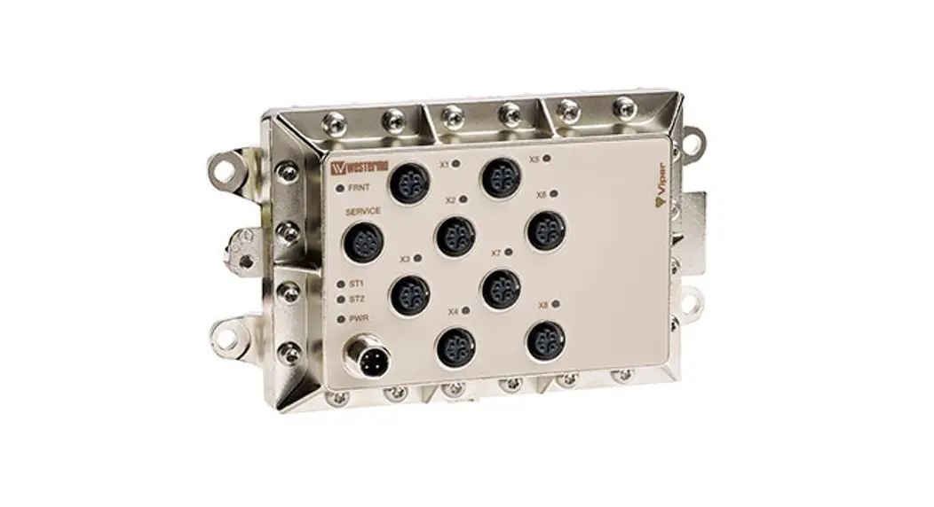
Viper 408
Managed 8-port Ethernet Switch
General Information
Legal Information
The contents of this document are provided “as is”. Except as required by applicable law, no warranties of any kind, either express or implied, including, but not limited to, the implied warranties of merchantability and fitness for a particular purpose, are made in relation to the accuracy and reliability or contents of this document. Westermo reserves the right to revise this document or withdraw it at any time without prior notice.
Under no circumstances shall Westermo be responsible for any loss of data or income or any special, incidental, consequential, or indirect damages howsoever caused.
More information about Westermo can be found at www.westermo.com
License and Copyright for Included Free/Libre Open Source Software
This product includes software developed by third parties, including Free/Libre Open Source Software (FLOSS). The specific license terms and copyright associated with the software are included in each software package respectively. Please visit the product web page for more information.
Upon request, the applicable source code will be provided. A nominal fee may be charged to cover shipping and media. Please direct any source code request to your normal sales or support channel.
Safety and Regulations
Warning signs are provided to prevent personal injury and/or damage to the product.
The following levels are used:
| Level of warning | Description | Consequence personal injury | Consequence material damage |
| Indicates a potentially hazardous situation | Possible death or major injury | Major damage to the product |
| Indicates a potentially hazardous situation | Minor or moderate injury | Moderate damage to the product |
| Provides information in order to avoid misuse of the product, confusion, or misunderstanding | No personal injury | Minor damage to the product |
| Used for highlighting general, but important information | No personal injury | Minor damage to the product |
 WARNING
 CAUTION
 NOTICE
 NOTE
NOTEBefore Installation
Read this manual completely and gather all information on the product. Make sure that you understand it fully. Check that your application does not exceed the safe operating specifications for this product.
![]() SAFETY DURING INSTALLATION
SAFETY DURING INSTALLATION
The product must be installed by qualified service personnel and built into an apparatus cabinet or similar, where access is restricted to service personnel only.
Refer to Compliance Information to see the required level of qualified service personnel according to safety standards.
During installation, ensure a protective earthing conductor is first connected to the protective earthing terminal (only valid for metallic housings). Westermo recommends a cross-sectional area of at least 4 mm2.
Upon removal of the product, ensure that the protective earthing conductor is disconnected last.
![]() HAZARDOUS VOLTAGE
HAZARDOUS VOLTAGE
Do not open an energized product. Hazardous voltage may occur when connected to a power supply.
![]() PROTECTIVE FUSE
PROTECTIVE FUSE
The power supply wiring must be sufficiently fused. The fuse must be IEC 60127 certified and rated for T1.25 A and 250 V.
It must be possible to disconnect manually from the power supply.
Ensure compliance with national installation regulations.
This product has no internal fuse and should be connected via an external fuse for protection.
![]() REDUCE THE RISK OF FIRE
REDUCE THE RISK OF FIRE
To reduce the risk of fire, use only telecommunication line cords with a cable diameter of AWG 26 or larger. Regarding power cable dimensions, see Interface Specifications.
![]() HOT SURFACE
HOT SURFACE
Be aware that the surface of this product may become hot. When it is operated at high temperatures, the external surface may exceed Touch Temperature Limit according to the product’s relevant electrical safety standard.
![]() ELECTROSTATIC DISCHARGE (ESD)
ELECTROSTATIC DISCHARGE (ESD)
Prevent electrostatic discharge damage to internal electronic parts by discharging your body to a grounding point (e.g. use a wrist strap).
Care Recommendations
Follow the care recommendations below to maintain the full operation of the product and to fulfill the warranty obligations:
- Do not drop, knock or shake the product. Rough handling above the specification may cause damage to internal circuit boards.
- Use a dry or slightly water-damp cloth to clean the product. Do not use harsh chemicals, cleaning solvents, or strong detergents.
- Do not paint the product. Paint can clog the product and prevent proper operation.
If the product is used in a manner not according to specification, the protection provided by the equipment may be impaired.
If the product is not working properly, contact the place of purchase, nearest Westermo distributor office, or Westermo technical support.
Product Disposal
![]() This symbol means that the product shall not be treated as unsorted municipal waste when disposed of it. It needs to be handed over to an applicable collection point for recycling electrical and electronic equipment.
This symbol means that the product shall not be treated as unsorted municipal waste when disposed of it. It needs to be handed over to an applicable collection point for recycling electrical and electronic equipment.
By ensuring this product is disposed of correctly, you will help to reduce hazardous substances and prevent potential negative consequences to both environment and human health, which could be caused by inappropriate disposal.
Compliance Information
Agency Approvals and Standards Compliance
Type | Approval/Compliance |
| EMC | EN 61000-6-1, Immunity residential environments |
| EN 61000-6-2, Immunity industrial environments | |
| EN 61000-6-3, Emission residential environments | |
| EN 61000-6-4, Emission industrial environments | |
| EN 50121-3-2, Railway applications – EMC: Rolling stock – Apparatus | |
| EN 50121-4, Railway signaling and telecommunications apparatus | |
| IEC 62236-4, Railway signaling and telecommunications apparatus | |
| E-Mark, Road Vehicles, E1 no: 10 R – 047216* | |
| Environmental | EN 50155 Railway applications – Electronic equipment used on rolling stock |
| EN 61373 – Railway applications – Rolling stock equipment. Shock and vibration tests | |
| IEEE 1478 – Environmental conditions for transit rail car electronic equipment | |
| EN 50124-1 – Railway applications – Insulation coordination | |
| IEC 60068-2-27, (shock 10 g. 11 ms), IEC 60068-2-64 | |
| Fire protection | EN 45545-2, Fire protection on railway vehicles |
| Safety | EN/IEC/UL 62368-1, Safety Requirements for audio/video, information, and communication technology equipment |
Note * _ Applicable only for 3641-6360
EN/IEC/UL 62368-1 Notice
This product has been tested and found compliant with EN/IEC/UL 62368-1, Safety for Communication Technology. In accordance with the definitions of the standard, this product shall be handled by ordinary personnel. Energy source classifications are according to the following:
| EN/IEC/UL 62368-1 notice | ||
| Electrical energy source | Power port | ES1 (at 24 VDC) ES3 (at 110 VDC) |
| Serial port | ES1 | |
| Ethernet port | ES1, TNV-1 | |
| Power source | Power port | PS3 |
| Thermal energy source | Enclosure | TS1 |
| Mechanical energy source | Enclosure | MS1 (MS3 for wall or ceiling mounting) |
| Radiation energy source | N/A | N/A |
FCC Part 15.105 Notice:
This equipment has been tested and found to comply with the limits for a Class B digital device, pursuant to Part 15 of the FCC Rules. These limits are designed to provide reasonable protection against harmful interference in a residential installation. This equipment generates, uses, and can radiate radio frequency energy and, if not installed and used in accordance with the instructions, may cause harmful interference to radio communications. However, there is no guarantee that interference will not occur in a particular installation. If this equipment does cause harmful interference to radio or television reception, which can be determined by turning the equipment off and on, the user is encouraged to try to correct the interference by one or more of the following measures:
- Reorient or relocate the receiving antenna
- Increase the separation between the equipment and receiver
- Connect the equipment into an outlet on a circuit different from that to which the receiver is connected
- Consult the dealer or an experienced radio/TV technician for help.
Declaration of Conformity
Hereby, Westermo declares that this product is in compliance with applicable EU directives and UK legislation. The full declaration of conformity and other detailed information is available at www.westermo.com/support/product-support.
![]()
![]()
Type Tests and Environmental Conditions
| Phenomena | Test | Description | Test levels |
| ESD | EN 61000-4-2 | Enclosure contact | ± 6 kV (crit A) |
| Enclosure air | ± 8 kV (crit A) | ||
| RF field AM modulated | IEC 61000-4-3 | Enclosure | 20 V/m 80% AM (1 kHz), 80 – 2700 MHz (crit A) 10 V/m 80% AM (1 kHz), 2700 – 6000 MHz (crit A) |
| Fast transient | EN 61000-4-4 | Ethernet ports | ± 2 kV (crit A) |
| Power port | ± 2 kV (crit A) | ||
| Earth port | ± 2 kV (crit A) | ||
| Surge | EN 61000-4-5 | Fault port | ± 2 kV line to earth (crit A) |
| Ethernet ports | ± 2 kV line to earth (crit A) | ||
| Power port | ± 2 kV line to earth, ± 2 kV line to line (crit A) | ||
| RF conducted | EN 61000-4-6 | Ethernet ports | 10 V 80% AM (1 kHz), 0.15 – 80 MHz (crit A) |
| Power port | 10 V 80% AM (1 kHz), 0.15 – 80 MHz (crit A) | ||
| Power frequency magnetic field | EN 61000-4-8 | Enclosure | 1000 A/m 50 Hz 300 A/m 16.7 Hz, 60 Hz, DC (crit A) |
| Pulse magnetic field | EN 61000-4-9 | Enclosure | 300 A/m (crit A) |
| Voltage dips and interruption | EN 50155 | DC power ports | 10 ms interruption, 100 ms ±40% voltage variation |
| Radiated emission | CISPR 16-2-3 ANSI C63.4 (FCC part 15) | Enclosure | Class B (30 – 6000 MHz) |
| Conducted emission | CISPR 16-2-1 | DC power port & Ethernet ports | Class B |
| Dielectric strength | EN 50155 | Ethernet ports to other isolated ports | 500 VAC 1 min |
| Power & Fault port to other isolated ports | 1500 VAC 1 min | ||
| Temperature | EN 60068-2-1 EN 60068-2-2 | Operating | -40 to +70ºC |
| Storage & Transport | -40 to +85ºC | ||
| Humidity | EN 60068-2-30 | Operating | 5 to 95% relative humidity |
| Storage & Transport | 5 to 95% relative humidity | ||
| Altitude | Operating | 2000 m / 70 kPa | |
| Reliability prediction (MTBF) | MIL-HDBK- 217F, GB | Operating | 118 years @ 25ºC 116 years @ 40ºC |
| Service life | Operating | 10 years | |
| Vibration, random simulated long life | IEC 60068-2-64, Cat. 1 class B (EN 61373) | Not Operating | Vertical: 7.9 m/s2 Transverse: 7.9 m/s2 Longitudinal: 7.9 m/s2 3 x 5 h |
| Vibration, random functional | IEC 60068-2-64, Cat. 1 class B (EN 61373) | Operating | Vertical: 1.0 m/s2 Transverse: 1.0 m/s2 Longitudinal: 1.0 m/s2 3 x 10 min |
| Shock, half sine pulses | IEC 60068-2-27, Cat. 1 class B (EN 61373) | Operating | Vertical: 50 m/s2 Transverse: 50 m/s2 Longitudinal: 50 m/s2 30 ms, 3 x 6 shocks |
| Shock, sawtooth | IEC 60068-2-27, Cat. 1 class B (IEEE1478-2001) | Operating | Vertical: 100 m/s2 Transverse: 100 m/s2 Longitudinal: 100 m/s2 11 ms, 3 x 6 shocks |
| Enclosure | UL 94 | Nickel coated zinc | Flammability class V-1 |
| Dimension W x H x D | 175 x 100 x 50 mm | ||
| Weight | 0.9 kg | ||
| Degree of protection | IEC 529 | Enclosure | IP 65 when all ports are protected/ connected |
| Cooling | Convection | ||
| Mounting | Wall-mounted |
Description
Viper-408 is a switch developed for rail and industrial applications. To meet the environmental requirements from rail and harsh industrial applications the switch has rugged M12 Ethernet connectors and full metal housing. The switch fulfills IP65 degree of protection when all ports are protected/connected. Our unique FRNT (Fast Recovery of Network Topology) technology is the fastest protocol on the market to reconfigure a network in the event of any failure of a link or hardware. Real-time properties are implemented in order to achieve determinism for real-time-critical applications. Viper408 supports QoS (Quality of Service) with four priority queues and strict priority scheduling as well as HoL (Head of Line Blocking Prevention). All to assure that the data network is deterministic.
Interface Specifications
| Power and fault relay port PWR | |
| Rated voltage | 24 to 110 VDC |
| Operating voltage | 16.8 to 143 VDC (14.4 to 154 for 100 ms) |
| Rated current | 140 mA @ 24 VDC 40 mA @ 110 VDC |
| Rated frequency | DC |
| Inrush current, I2t | Max 0.02 A2s @ 24 – 110 VDC |
| Startup current * | 300 mA @ 16.8 VDC |
| Polarity | Reverse polarity protected |
| Redundant power input | No |
| Isolation to | Connections X1 – X8 and to ground 1500 VAC. Fault relay belongs to the same isolation group as the power supply lines (fault relay signals are also contained within PWR). |
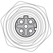
| Connection | 4 pin male M12 connector with A-code |
| Connector size | M12, recommended cable area 0.5 mm2 recommended (minimum 0.25 mm2), cable dimensions depend on the choice of M12 connector |
| Shielded cable | Not required, twisted pair is recommended |
| Fault relay resistance | < 10 Ω |
| Operating voltage | Up to 110 VDC |
| Max continuous current | 250 mA |
* If an external power supply is used it must meet the specified startup current.
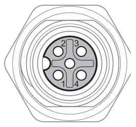 M12 A-coded Power Connector | Position | Direction | Description |
| 1 | U+ | Positive supply voltage | |
| 2 | Out | Alarm relay (status) + | |
| 3 | 0 V | Negative supply voltage | |
| 4 | Out | Alarm relay (status) – | |
| Housing | Shield | Chassis of the product (ground) |
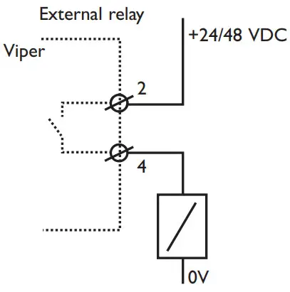
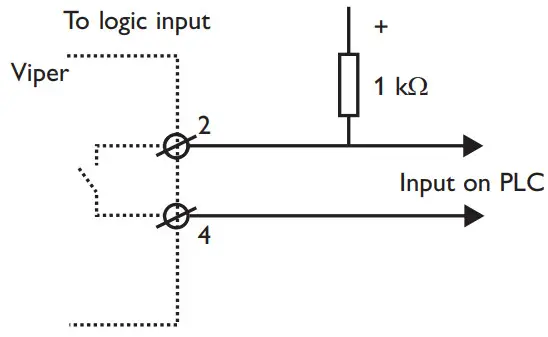
Fault Contact
The Viper switch is equipped with a potential free normally closed fault contact. The fault contact is a solid-state component (relay) that requires power to work and it is transient protected. Additionally, the fault contact is opened when any of the following conditions are met:
- No voltage on the power supply pin, a voltage level outside the legal voltage range, or current limitation on the voltage source is applied on the power input.
- Link alarm i.e. missing link on any Ethernet port that has link alarm enabled.
- Redundancy Mode activated i.e. one or more FRNT link is down.
A description of how the connection to the fault contact could be done is shown below. The relay is closed when the unit is OK and open at failure. The relay is of semiconductor type (no moving parts). It is specified for max current 250 mA continuous, 500 mA peak (10 ms), operational voltage up to 110 V, protected by a 150 VDC-varistor, ON-resistance less than 10 Ohm, and leakage current max 1 µA.
 |  |
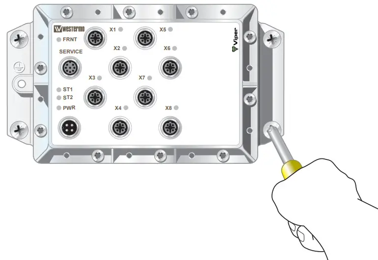
Service Port
The service port should not be used by nonother than the Westermo technical support team. Do not connect any device or cable to the service port.
| Ethernet TX port X1 to X8 | |
| Electrical specification | IEEE std 802.3. 2000 Edition |
| Data rate | 10 Mbit/s or 100 Mbit/s, manual or auto |
| Duplex | Full or half, manual or auto |
| Circuit type | TNV-1 |
| Transmission range | 150 m |
| Isolation to | Other Ethernet ports, 500 VAC PWR, 1500 VAC |
| Galvanic connection to | None, except for shielded contact to housing |
| Connection | 4-pole M12 female with D-code |
| Shielded cable | Not required, twisted pair is recommended |
| Conductive housing | Nickel-plated zinc, metal housings of X1-X8 also connected to the housing |
| Number of ports | 8 Ethernet (X1-X8) |
 | Position | Direction | Description |
| 1 | Out | Transmit Data + | |
| 2 | In | Receive Data + | |
| 3 | Out | Transmit Data – | |
| 4 | In | Receive Data – | |
| Housing | Shield | Chassis of the product (ground) |
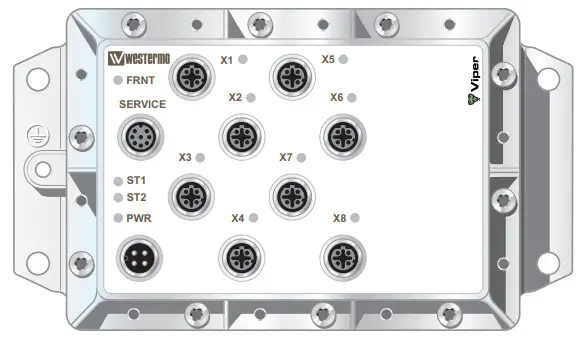
Location of Interface Ports, LEDs
LED indicators
| LED | Status | Description |
| PWR | GREEN | The unit indicates no-fault |
| RED | Unit indicated fault | |
| FLASH | Connected to IP Configuration tool | |
| FRNT | OFF | FRNT is not enabled or not supported |
| GREEN | FRNT is running and the switch is configured as members switch in the ring. | |
| GREEN FLASH | FRNT is running and the switch is configured as Focal Point | |
| RED | FRNT Error | |
| ST1 | GREEN | Indicates STP root |
| ST2 | NC | |
| X1 to X8 | OFF | No Link |
| GREEN | Link is up | |
| GREEN FLASH | Data is transmitted | |
| YELLOW ON | Port alarm and no link. If RSTP/FRNT mode is activated, the port is blocked. |
Configuration
The units can easily be configured via the onboard Web-based configuration tool. Local IP addresses can also be configured by using the Westermo IP Configuration tool, from the IP Configuration tool it is then possible to browse into the unit for further configuration.
IP Address
When delivered, the default IP address of the Viper is 192.168.2.200.
Default gateway 192.168.2.200
If the default address of the unit is valid in the connected network it is possible to access the unit directly from a web browser.
Change Local IP Address
The local address of Viper can be configured using the IP Configuration tool, then it is possible to browse into the unit for further configuration. The IP Configuration program is available on the CD or for download from the Westermo web page: http://www.westermo.com, choose Downloads/Software/Ethernet/Ethernet switches Name: IP config Westermo.zip
Install the software and start the application from a PC on the network connected to the same network as the Viper. Make sure that the Default IP of the configuration software (see figure below) is in the same subnet as your PC.
![]() If you are not sure about the subnet – consult your network administrator. IP Config version must be 10.0.0 or higher.
If you are not sure about the subnet – consult your network administrator. IP Config version must be 10.0.0 or higher.
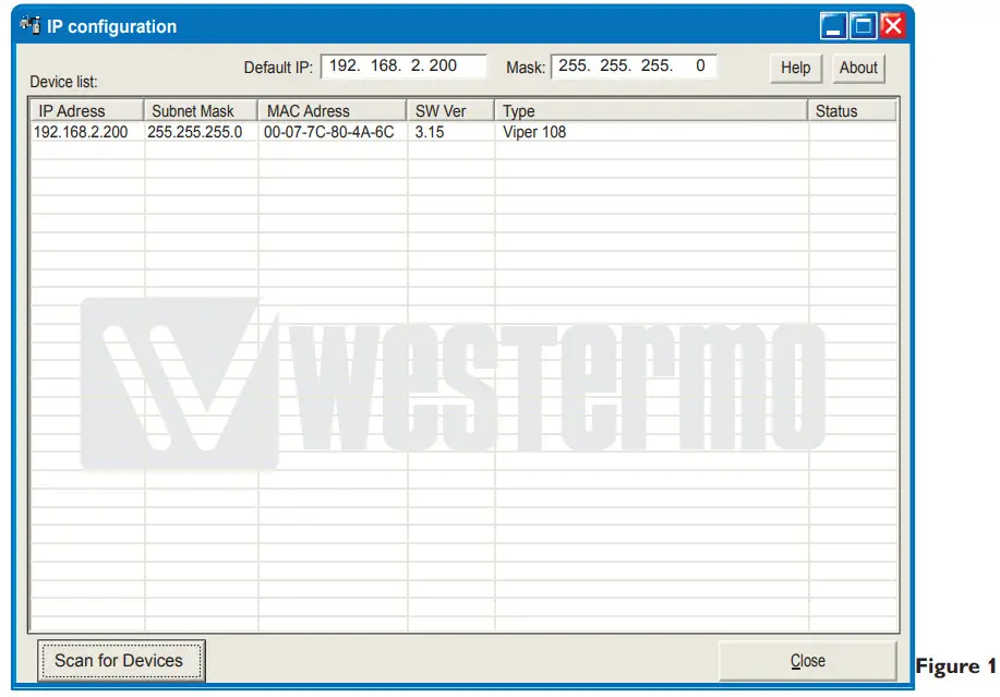
By clicking the “Scan for Devices” button the IP Configuration tool will detect the switches/routers in the network. The software will list all Westermo managed switches or routers connected to the network. Information as in figure 1 will appear for each detected unit connected to the same network as your PC.
If you only want to change the IP address and the subnet mask, this can be done within the IP config tool.
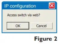
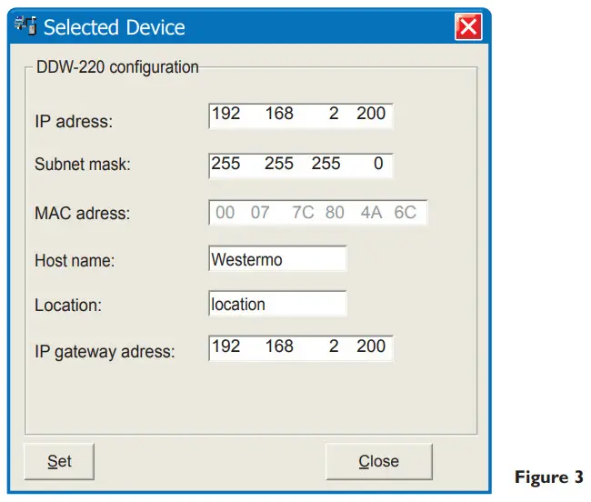
By clicking the listed Viper that you wish to be re-configured you will be asked if you would like to access it via the web figure 2. Click the abort button, enter the preferred IP address, Subnet mask, and IP gateway address and click the Set button to confirm the settings in the unit (see figure 3).
![]() If you are not sure about the settings – consult your network administrator.
If you are not sure about the settings – consult your network administrator.
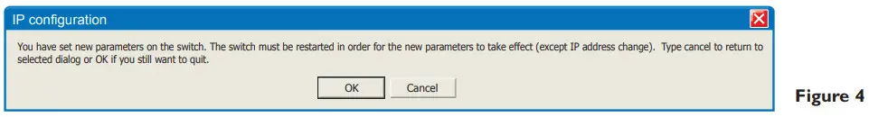
Click the Close button to get back to the main view. You will then be asked if you would like to quit. Click the OK button, figure 4, and you will be back to the main view of the IP Configuration program(see figure 1).
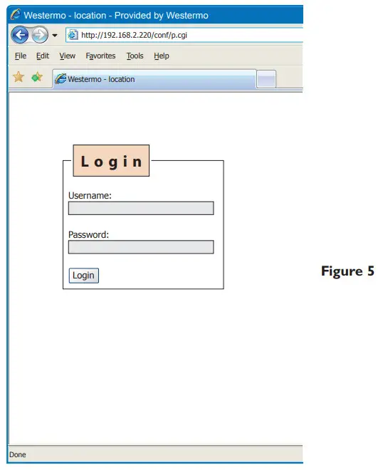
Click the Scan for switches button again and the settings you configured will appear in the list. Now you can access the Viper via the browser for further configuration by clicking the unit with an IP address that fits your subnet. Figure 2 will appear and when you click the OK button and a web browser will be opened and redirected to the Viper unit log-in page (see figure 5).
Log in via Web
You will be prompted with a Login screen where
the default settings for Username and Password are:
Username: admin
Password: westermo
The unit can be easily configured via the onboard Web-based configuration tool.
The network interface and switch properties can be configured and stored.
The Web tool also has an extended integrated help function describing all configuration options.
Max 10 characters can be used in the login. The following characters are not valid.
ASCII 34 = ”
ASCII 35 = #
ASCII 39 = ’’
ASCII 40 = (
ASCII 92 = \
Mounting
There are four 6 mm boreholes intended for mounting the unit. The unit can be mounted vertical or horizontal. The unit is wall mounted.
Removal
Disconnect all cables and unscrew the unit from the wall.
Cooling
This unit uses convection cooling. Avoid obstructing the airflow around the unit. Spacing is recommended for the use of the unit in the full operating temperature range and service life.
Factory Reset
The factory reset option restores the switch to its original factory condition.
The switch will be restored using the following settings.
- IP address 192.168.2.200
- Subnet mask 255.255.255.0
- Gateway 192.168.2.1
- All Ethernet ports are enabled and set to Auto Negotiate
- All applications are disabled
- Password reset to westermo
To perform a Factory Reset follow the procedure below. Read all steps before starting. If you have any doubts about whether the reset is performed or not, do NOT unplug the power supply, wait for confirmation according to step 5.
- Disconnect the power
- Connect cables between port x1-x6 and port x2-x5.
- Apply power
- Wait for approximately 90 seconds. (Some LEDs will flash during start-up
- When the Green LED’s on all Ethernet ports are constantly on, then remove the cables connected to ports x1-x6 and x2-x5.
- It is now safe to remove the power and restart the switch.
- When the switch has started up it will have the default settings.
![]() If the power is removed before the factory reset has finished, the switch may become unusable.
If the power is removed before the factory reset has finished, the switch may become unusable.
Dimensions
Measurements are stated in millimeters.
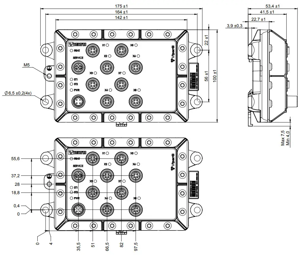
![]()
Westermo • Metallverksgatan 6, SE-721 30 Västerås, Sweden
Tel +46 16 42 80 00 Fax +46 16 42 80 01
E-mail: [email protected]
www.westermo.com


