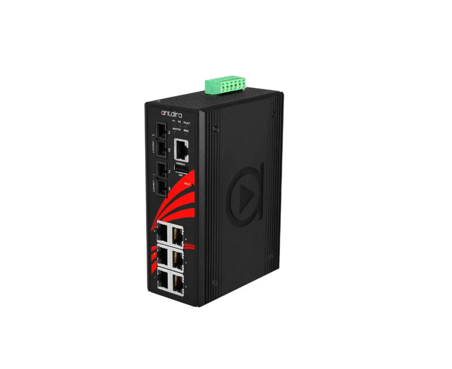
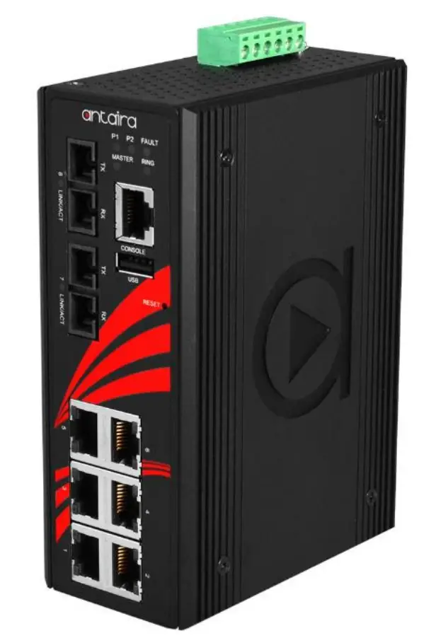
antaira LMX-0802-XX Series 8-Port Industrial Managed Ethernet Switch
Package Check List
The package contains the following items:
- 1 – Quick installation guide
- 1 – LMX-0802-XX(-T) Series
- 1 – Wall mounting bracket set with screws
- 1 – RJ45 to DB9 Serial Console cable
- 1 – DC cable –18 AWG & DC jack 5.5 x 2.1mm
- 1 – Dust cover set
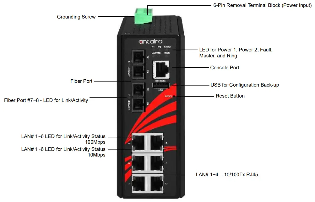
Front Panel Layout
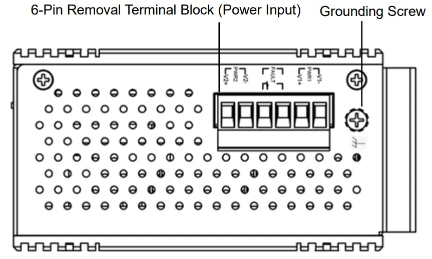
Top Panel View
LMX-0802-XX series top panel is equipped with one 6-pin removal terminal block connector for dual DC power inputs (12~48VDC).
Product Overview
System Interface/Performance
- All RJ45 ports support the auto MDI/MDI-X function
- Ethernet connectivity 4*10/100Tx RJ45 ports and 1*100Fx (SC/ST) fiber ports with multi-mode (2km) or single-mode (30km)
- Store-and-forward switching architecture
- 8K MAC address table
Power Input & Connection
- DC 12 to 48V redundant power, with a 6-pin removal terminal block
- It is recommended to use a UL listed industrial power supply
Operating Temperature
- Standard operating temperature model: -10°C to 70°C
- Extended operating temperature model: -40°C to 75°C
Case/Installation
- IP30 protection
- DIN-Rail and wall mount design
LED Indicators
LED | Color | Description | |
Power 1 | Green | On | Power input 1 is active |
Off | Power input 1 is inactive | ||
Power 2 | Green | On | Power input 2 is active |
Off | Power input 2 is inactive | ||
Fault | Green/Red | Green | Preconfigured alarms are not detecting failure |
Red | Preconfigured alarms are detecting failure | ||
Off | Switch is in the process of booting | ||
Master | Green | On | ERPS Owner Mode (Ring Master) is ready |
Off | ERPS Owner Mode is not active | ||
Ring | Green | On | Ring Network is active |
Off | Ring Network is not active | ||
LAN Port 1~6 (Upper LED) | 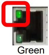 | On | Connected to network, 100Mbps |
Flashing | Networking is active | ||
Off | Not connected to network | ||
LAN Port 1~6 (Lower LED) | 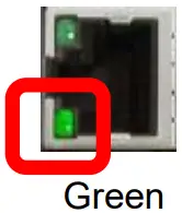 | On | Connected to network, 10Mbps |
Flashing | Networking is active | ||
Off | Not connected to network | ||
Fiber Port 7~8 LNK/ACT | Green | On | Connected to network, 100Mbps |
Flashing | Networking is active | ||
Off | Not connected to network | ||
Ethernet Ports
RJ45 Ports (Auto MDI/MDIX)
All RJ45 ports are auto-sensing for 10Base-T, 100Base-TX or 1000Base-T device connections. Please follow the wiring pin assignment table below for Ethernet port installation.
RJ45 Ethernet Port Pin Outs | ||||
Pins | T568A Color | T568B Color | 10Base-T, 100Base-TX | 1000 Base-T(X) |
Pin 1 | white/green stripe | white/orange stripe | Rx+ | TP0+ |
| Pin 2 | green solid | orange solid | Rx- | TP0- |
Pin 3 | white/orange stripe | white/green stripe | Tx+ | TP1+ |
| Pin 4 | blue solid | blue solid | unused | TP2+ |
Pin 5 | white/blue stripe | white/blue stripe | unused | TP2- |
| Pin 6 | orange solid | green solid | Tx- | TP1- |
Pin 7 | white/brown stripe | white/brown stripe | unused | TP3+ |
| Pin 8 | brown solid | brown solid | unused | TP3- |
Power Input Wiring
Please follow the steps below to insert the power wire:
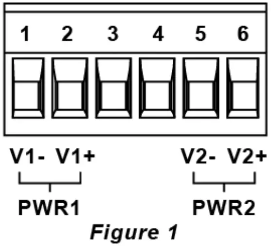
- Insert the positive and negative wires into the PWR1 (V1+, V1-) and PWR2 (V2+, V2-) contacts on the terminal block connector as shown below in Figure 1.

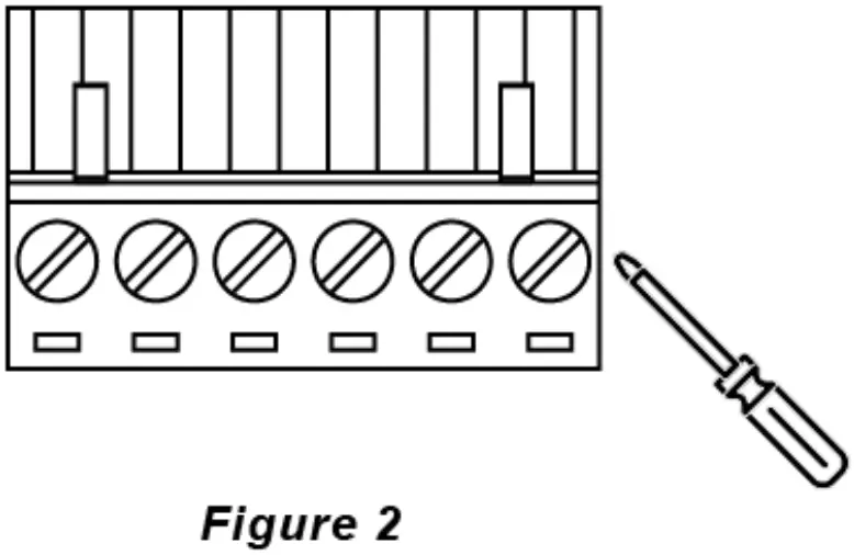
- Tighten the wire-clamp screws to prevent the wires from loosening, as shown below in Figure 2.

Industrial Switch Mounting
DIN-Rail Mounting
The DIN-Rail bracket is pre-installed on the industrial Ethernet switch from the factory. Please refer to Figure 3 for a DIN-Rail bracket installation reference. Follow the steps below for installing the industrial switch on the DIN-Rail track: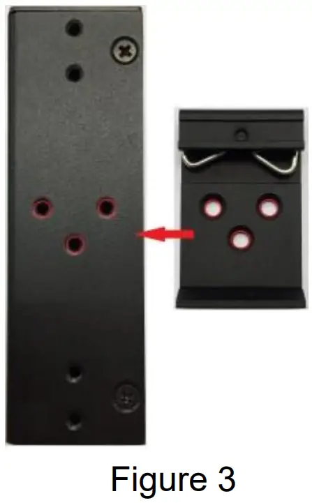
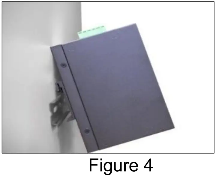
- Insert the top of the DIN-Rail on to the track as shown below in Figure 4.

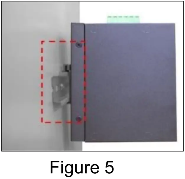
- Lightly pull down the bracket on to the rail as shown below in Figure 5.

- Check if the bracket is mounted tightly on the rail.
- To remove the industrial Ethernet switch from the rail, do the opposite from the steps above.
Wall Mounting
Follow the steps below to mount the industrial Ethernet switch using the wall mounting bracket as shown below in Figure 6.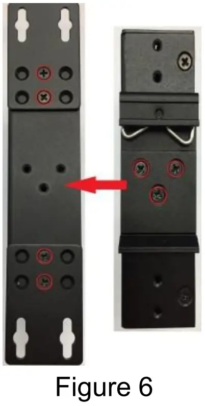
- Remove the DIN-Rail bracket from the industrial Ethernet switch by loosening the screws.
- Place the wall mounting brackets on the top and bottom of the industrial Ethernet switch.
- Use the screws to screw the wall mounting bracket on the industrial Ethernet switch.
- Use the hook holes at the corners of the wall mounting bracket to hang the industrial Ethernet switch on the wall.
- To remove the wall mount bracket, do the opposite from the steps above.
Field Maintenance and Service
- If the device requires servicing of any kind, the user is required to disconnect and remove it from its mounting. The initial installation should be done in a way that makes this as convenient as possible.
- Voltage/power lines should be properly insulated as well as other cables. Be careful when handling them so as to not trip over.
- Do not under any circumstance insert foreign objects of any kind into the heat dissipation holes located in the different faces of the device. This may not only harm the internal layout, but might cause harm to user as well.
- Do not under any circumstance open the device for any reason. Please contact your dealer for any repair needed or follow the instructions within the manual.
Warranty Policy
Warranty Conditions
Products supplied by Antaira Technologies are covered in this warranty for sub-standard performance or defective workmanship. The warranty is not, however, extended to goods damaged in the following circumstances:
(a) Excessive forces or impacts
(b) War or an Act of God: wind storm, fire, flood, electric shock, earthquake
(c) Use of unqualified power supply, connectors, or unauthorized parts/kits
(d) Replacement with unauthorized parts
RMA and Shipping Costs Reimbursement
Customers shall always obtain an authorized “RMA” number from Antaira before shipping the goods for repair or replacement.
- Within the warranty period (based on the invoice date), all parts and labor are free of charge to the customers.
- Customers are responsible for the cost of parts and labor, if the products are out of warranty.
- For RMA service, customers are responsible for the shipping expense for shipping the RMA unit(s) to Antaira. Antaira is responsible for the shipping expense via a ground service for the return repair/replace unit(s) back to customers.
Limited Liability
Antaira would not be held responsible for any consequential losses from using Antaira’s product.
Warranty Period
5-Year Warranty
Antaira’s Customer Service and Support
• Antaira’s Technical Service & Support Centers:
+ 844-268-2472 (Antaira US Headquarter)
+ 48-22-862-88-81 (Antaira Europe Office)
+ 886-2-2218-9733 (Antaira Asia Office)
• Antaira’s Web Sites & Repair/Support Emails:
www.antaira.com / [email protected]
www.antaira.eu / [email protected]
www.antaira.com.tw / [email protected]
*Any changes will be announced on the Antaira website.