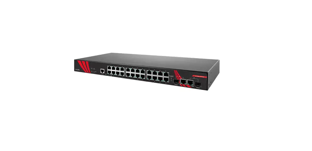
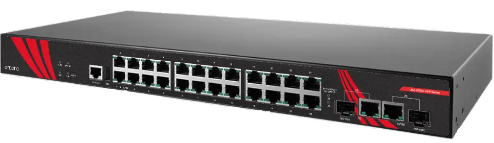
antaira LMX-2602G-SFP Series 26 Port Industrial Rackmount Gigabit Managed Ethernet Switch
Package Check List
The package contains the following items:
- 1 – Quick installation guide
- 1 – LMX-2602G-SFP(-T)
- 1 – RJ45 dust cover set
- 1 – Set of rack-mounting brackets and screws
- 1 – RJ45 to DB9 serial console cable
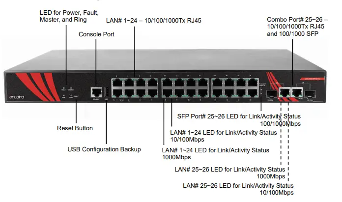
Front Panel Layout
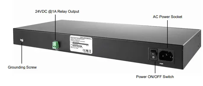
Back Panel View
LMX-2602G-SFP series back panel is equipped with one AC power inputs socket (90~264VAC) and one 2-pin removal terminal block for relay output.
Product Overview
System Interface/Performance
- All RJ45 ports support the auto MDI/MDI-X function
- Embedded 24*10/100/1000Tx RJ45 ports and 2*gigabit combo ports (2*10/100/1000Tx and 2*100/1000 SFP slots)
- Store-and-forward switching architecture
- 8K MAC address table
Power Input & Connection
- AC 90 to 264V redundant power, with AC socket
- It is recommended to use a UL listed industrial power supply
Operating Temperature
- Standard operating temperature model: -10°C to 65°C
- Extended operating temperature model: -40°C to 75°C
Case/Installation
- IP40 protection
- Rackmount design
LED Indicators
| LED | Color | Description | |
| Power | Green | On | Power input is active |
| Off | Power input is inactive | ||
| Fault | Green | On | No event happened |
| Red | Off | 1. Power input 1 or 2 is inactive 2. Port link-down / Broken | |
| Master | Green | On | ERPS Owner Mode (Ring Master) is ready |
| Off | ERPS Owner Mode is not active | ||
| Ring | Green | On | ERPS Ring Network is active |
| Flashing | ERPS Ring works abnormally or misconfigure | ||
| Off | ERPS Ring Network is not active | ||
| LAN Port 1~24 (Left LED) | 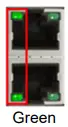 | On | Connected to network, 1000Mbps |
| Flashing | Networking is active | ||
| Off | Not connected to network | ||
| LAN Port 1~24 (Right LED) | 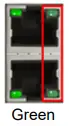 | On | Connected to network, 10/100Mbps |
| Flashing | Networking is active | ||
| Off | Not connected to network | ||
| Combo Port 25~26 (Left LED) |  | On | Connected to network, 1000Mbps |
| Flashing | Networking is active | ||
| Off | Not connected to network | ||
| Combo Port 25~26 (Right LED) |  | On | Connected to network, 10/100Mbps |
| Flashing | Networking is active | ||
| Off | Not connected to network | ||
| SFP Port 25~26 (Link/Activity) | Green | On | Connected to network, 1000Mbps |
| Flashing | Networking is active | ||
| Off | Not connected to network | ||
| Amber | On | Connected to network, 100Mbps | |
| Flashing | Networking is active | ||
| Off | Not connected to network | ||
Installation
Ethernet Ports
RJ45 Ports (Auto MDI/MDI-X) All RJ45 ports are auto-sensing for 10Base-T, 100Base-TX or 1000Base-T device connections. Please follow the wiring pin assignment table below for Ethernet port installation.
| RJ45 Ethernet Port Pin Outs | ||||
| Pins | T568A Color | T568B Color | 10Base-T, 100Base-TX | 1000 Base-T(X) |
| Pin 1 | white/green stripe | white/orange stripe | Rx+ | TP0+ |
| Pin 2 | green solid | orange solid | Rx- | TP0- |
| Pin 3 | white/orange stripe | white/green stripe | Tx+ | TP1+ |
| Pin 4 | blue solid | blue solid | unused | TP2+ |
| Pin 5 | white/blue stripe | white/blue stripe | unused | TP2- |
| Pin 6 | orange solid | green solid | Tx- | TP1- |
| Pin 7 | white/brown stripe | white/brown stripe | unused | TP3+ |
| Pin 8 | brown solid | brown solid | unused | TP3- |
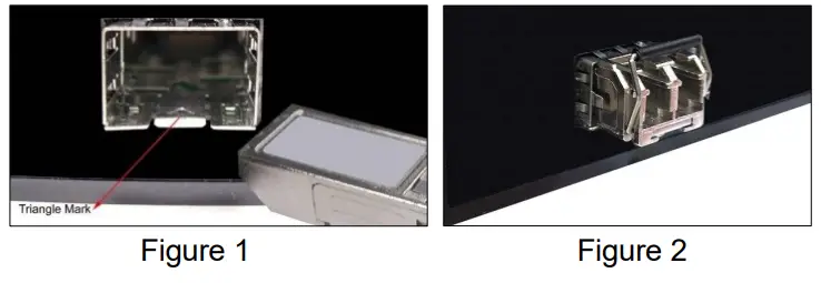
SFP Slots
The Small Form-Factor Pluggable (SFP) is a compact optical transceiver used in optical communications.
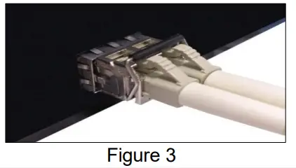
Please follow the steps below for connecting the SFP and LC cable:
- Insert the SFP transceiver module into the SFP slot as shown below in Figure 1 (Notice that the triangle mark is at the bottom of the SFP slot). Figure 2 shows the SFP transceiver module was inserted.

- Insert the fiber cable of the LC connector into the transceiver as shown below in Figure 3.

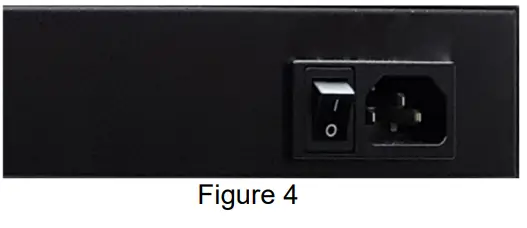
Power Input Wiring
Please follow the below steps:
- Put the power switch into the off position.
- Insert the AC power cable into the universal AC socket as shown in Figure 4.

- Switch the power switch for power on.
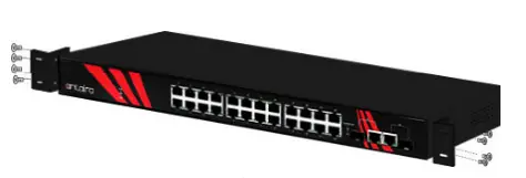
Industrial Switch Mounting
The switch comes with a rack-mounted kit can be mounted in an EIA standard size, 19-inch rack. It can be placed in a wiring closet with other equipment.
Perform the following steps to rack-mount the switch.
- Position one plate to align with the holes on one side of the hub and secure it with the smaller plate screws. Then, attach the remaining plate to the other side of the switch.
- After attaching both mounting plates, position the switch in the rack by lining up the holes in the plates with the appropriate holes on the rack. Secure the switch to the rack with a screwdriver and the rack-mounting screws.

*Note: For proper ventilation, allow at least 4 inches (10 cm) of clearance on the front and 3.4 inches (8 cm) on the back of the switch. This is especially important for enclosed rack installation.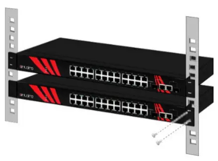
Field Maintenance and Service
- If the device requires servicing of any kind, the user is required to disconnect and remove it from its mounting. The initial installation should be done in a way that makes this as convenient as possible.
- Voltage/power lines should be properly insulated as well as other cables. Be careful when handling them so as to not trip over.
- Do not under any circumstance insert foreign objects of any kind into the heat dissipation holes located in the different faces of the device. This may not only harm the internal layout, but might cause harm to user as well.
- Do not under any circumstance open the device for any reason. Please contact your dealer for any repair needed or follow the instructions within the manual.
Warranty Policy
Warranty Conditions
Products supplied by Antaira Technologies are covered in this warranty for sub-standard performance or defective workmanship. The warranty is not, however, extended to goods damaged in the following circumstances:
- (a) Excessive forces or impacts
- (b) War or an Act of God: wind storm, fire, flood, electric shock, earthquake
- (c) Use of unqualified power supply, connectors, or unauthorized parts/kits
- (d) Replacement with unauthorized parts
RMA and Shipping Costs Reimbursement
Customers shall always obtain an authorized “RMA” number from Antaira before shipping the goods for repair or replacement.
- Within the warranty period (based on the invoice date), all parts and labor are free of charge to the customers.
- Customers are responsible for the cost of parts and labor, if the products are out of warranty.
- For RMA service, customers are responsible for the shipping expense for shipping the RMA unit(s) to Antaira. Antaira is responsible for the shipping expense via a ground service for the return repair/replace unit(s) back to customers.
Limited Liability
Antaira would not be held responsible for any consequential losses from using Antaira’s product.
Warranty Period
5-Year Warranty
Antaira’s Customer Service and Support
- Antaira’s Technical Service & Support Centers:
- + 844-268-2472 (Antaira US Headquarter)
- + 48-22-862-88-81 (Antaira Europe Office)
- + 886-2-2218-9733 (Antaira Asia Office)
- Antaira’s Web Sites & Repair/Support Emails:
*Any changes will be announced on the Antaira website.
Tel: 1-844-268-2472
Fax: 1-714-671-9944
www.antaira.com


