westermo SDW-500 series Industrial Ethernet 5-port Switch
General information
Legal information
The contents of this document are provided “as is”. Except as required by applicable law, no warranties of any kind, either express or implied, including, but not limited to, the implied warranties of merchantability and fitness for a particular purpose, are made in relation to the accuracy and reliability or contents of this document. Westermo reserves the right to revise this document or withdraw it at any time without prior notice.
Under no circumstances shall Westermo be responsible for any loss of data or income or any special, incidental, and consequential or indirect damages howsoever caused.
More information about Westermo can be found at www.westermo.com
About This Guide
This guide is intended for installation engineers and users of the Westermo products.
It includes information on safety and regulations, a product description, installation instructions and technical specifications.
Safety and Regulations
Warning signs are provided to prevent personal injuries and/or damages to the product. The following levels are used:
| Level of warning | Description | Consequence personal injury | Consequence material damage |
 WARNING | Indicates a potentially hazardous situation | Possible death or major injury | Major damage to the product |
 CAUTION | Indicates a potentially hazardous situation | Minor or moderate injury | Moderate damage to the product |
 NOTICE | Provides information in order to avoid misuse of the product, confusion or misunderstanding | No personal injury | Minor damage to the product |
 NOTE | Used for highlighting general, but important information | No personal injury | Minor damage to the product |
SAFETY DURING INSTALLATION
The product must be installed and operated by qualified service personnel and installed into an apparatus cabinet or similar, where access is restricted to service personnel only.
Before energising and connecting communication clables to the product, ensure a protective earthing conductor is first connected to the protective earthing terminal (only valid for metallic housings). Westermo recommends a cross-sectional area of at least 4 mm2.
If the product does not have a protective earthing terminal, then the DIN-rail must be connected to protective earth. Upon removal of the product, ensure that the protective earthing conductor, or the connection to earth via the DIN-rail, is disconnected last.
HAZARDOUS VOLTAGE
Do not open an energized product. Hazardous voltage may occur when connected to a power supply.
PROTECTIVE FUSE
The power supply wiring must be sufficiently fused. It must be possible to disconnect manually from the power supply. Ensure compliance to national installation regulations.
Replacing the internal fuse must only be performed by Westermo qualified personell.
REDUCE THE RISK OF FIRE
To reduce the risk of fire, use only telecommunication line cords with a cable diameter of AWG 26 or larger. Regarding power cable dimensions, see Interface Specifications.
CLASS 1 LASER PRODUCT
Do not look directly info a fibre optical port or any connected fibre, although the product is designed to meed the Class 1 Laser regulations and complies with 21 CFR 1040.10 and 1040.11.
FIBRE OPTIC HANDLING
Fibre optic equipment need special treatment. It is very sensitive to dust and dirt. If the fibre is disconnected from the product, the protective plugs on the transmitter/receiver must be connected. The protective plugs must be kept on during transportation. The fibre optics cables must be handled the same way.
CORROSIVE GASES
If the product is placed in a corrosive environment, it is important that all unused connector sockets are protected with a suitable plug, in order to avoid corrosion attacks on the gold plated connector pins.
ELECTROSTATIC DISCHARGE (ESD)
Prevent electrostatic discharge damages to internal electronic parts by discharging your body to a grounding point (e.g. use a wrist strap).
Care recommendations
Follow the care recommendations below to maintain full operation of product and to fulfil the warranty obligations:
- Do not drop, knock or shake the product. Rough handling above the specification may cause damage to internal circuit boards.
- Use a dry or slightly water-damp cloth to clean the product. Do not use harsh chemicals, cleaning solvents or strong detergents.
- Do not paint the product. Paint can clog the product and prevent proper operation.
If the product is used in a manner not according to specification, the protection provided by the equipment may be impaired.
If the product is not working properly, contact the place of purchase, nearest Westermo distributor office or Westermo technical support.
Cleaning of the optical connectors
In the event of contamination, the optical connectors should be cleaned by the use of forced nitrogen and some kind of cleaning stick.
Recommended cleaning fluids:
- Methyl-, ethyl-, isopropyl- or isobutyl-alcohol
- Hexane
- Naphtha
Product disposal
This symbol means that the product shall not be treated as unsorted municipal waste when disposing of it. It needs to be handed over to an applicable collection point for recycling electrical and electronic equipment.
By ensuring the product is disposed of correctly, you will help to reduce hazardous substances and prevent potential negative consequences to both environment and human health, which could be caused by inappropriate disposal.
Article number, model and description
| Article | Model | Description |
| 3644-0001 | SDW-550 | 10/100Base-T/TX: 5 ports |
| 3644-6001 | SDW-550 E-mark | 10/100Base-T/TX: 5 ports |
| 3644-0020 | SDW-541-MM-SC2 | 10/100Base-T/TX: 4 ports 100Base-FX: 1 port |
| 3644-0022 | SDW-541-SM-LC15 | 10/100Base-T/TX: 4 ports 100Base-FX: 1 port |
| 3644-0023 | SDW-541-MM-LC2 | 10/100Base-T/TX: 4 ports 100Base-FX: 1 port |
| 3644-0024 | SDW-541-SM-SC15 | 10/100Base-T/TX: 4 ports 100Base-FX: 1 port |
| 3644-0030 | SDW-532-MM-SC2 | 10/100Base-T/TX: 3 ports 100Base-FX: 2 port |
| 3644-0032 | SDW-532-SM-LC15 | 10/100Base-T/TX: 3 ports 100Base-FX: 2 port |
| 3644-0033 | SDW-532-MM-LC2 | 10/100Base-T/TX: 3 ports 100Base-FX: 2 port |
| 3644-0034 | SDW-532-SM-SC15 | 10/100Base-T/TX: 3 ports 100Base-FX: 2 port |
| 3644-0035 | SDW-532-SM-LC40 | 10/100Base-T/TX: 3 ports 100Base-FX: 2 port |
Simplified EU declaration of conformity
Hereby, Westermo declares that this product is in compliance with applicable EU directives and UK legislations. The full declaration of conformity and other detailed information is available at www.westermo.com/support/product-support.
Agency approvals and standards compliance
| Type | Approval / Compliance |
| EMC | EN 61000-6-2, Immproducty industrial environments |
| EN 61000-6-31, Emission residential environments | |
| EN 61000-6-42, Emission industrial environments | |
| E-Mark, Road Vehicles, 10R-04 72163 | |
| Safety | UL 60950-1, IT Equipment |
| Marine | DNV GL rules for classification – Ships and offshore products4 |
| Note | 1 _ Applicable only for 3644-x001 2 _ Applicable only for 3644-0019, 3644-002x and 3644-003x 3_ Applicable only for 3644-6001 4 – Applicable only for 3644-0001, 3644-0022 , 3644-0023, 3644-0025, 3644-0032, 3644-0033, 3644-0035 |
Corrosive environment:
This product has been successfully tested in a corrosion test according to IEC 60068-2-60, method 3. This means that the product meets the requirements to be placed in an environment classified as ISA-S71.04 class G3.
CORROSIVE GASES
If the product is placed in a corrosive environment, it is important that all unused connector sockets are protected with a suitable plug, in order to avoid corrosion attacks on the gold plated connector pins.
Environmental conditions
| Isolation between interfaces | |
| Power Interface to all other | 2.8 kV DC 2.0 kV RMS @ 50 Hz and 60 s duration |
| TX signal Interface to all other | 2.1 kV DC 1.5 kV RMS @ 50 Hz and 60 s duration |
| TX shield Interface to all other | 1.5 kV DC 1.0 kV RMS @ 50 Hz and 60 s duration |
| Environmental | |
| Temperature, operating | –25 to +70°C (SDW-550), –25 to +65°C (SDW-541) –25 to +60°C (SDW-532) |
| Temperature, storage and transportation | –25 to +70°C |
| Relative humidity, operating | 5 to 95% (non-condensing) |
| Relative humidity, storage and transportation | 5 to 95% (condensation allowed outside packaging) |
| Altitude, operating | 2000 m/70 kPa |
| Mechanical | |
| Dimension (W x H x D) | 35 x 121 x 119 mm |
| Weight | 0.2 kg |
| Mounting | DIN-rail |
| Degree of protection | IP21 |
Configuration
Auto configured (auto-negotiation) or manually setting of speed and duplex of individual TX port, by DIP-switches.
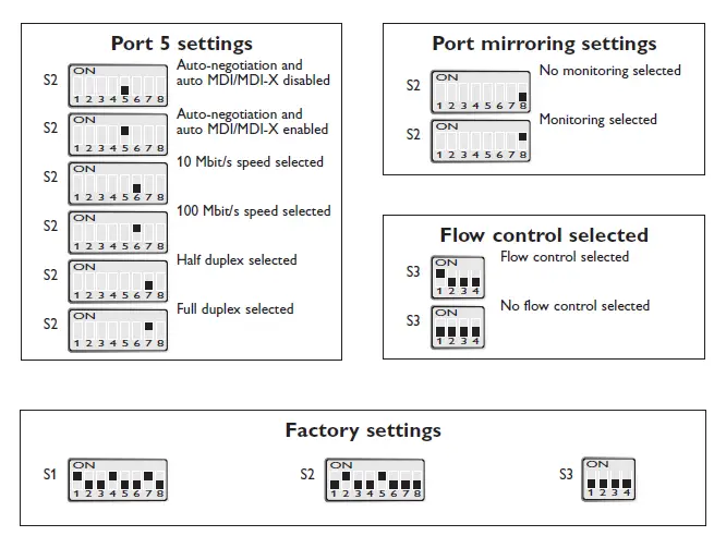
Port mirror function is possible to set with DIP-switch. With the port mirror function active the switch will copy all outgoing traffic to port 1. This can be used to monitor all traffic going out from the switch. Packets may be discarded if the total throughput exceeds the port speed of port 1.
Fibre optic power budget
| Model | Multimode MM-xx2 | Singlemode SM-SC15 | Singlemode SM-LC15 | Singlemode SM-LC40 |
| Transmitted wavelength | 1310 nm | 1310 nm | 1310 nm | 1310 nm |
| Min. output power, transmitter | –19 dBm | –15 dBm | –15 dBm | –5 dBm |
| Max. output power, transmitter | –12 dBm | –8 dBm | -8 dBm | 0 dBm |
| Input sensitivity, receiver | –31 dBm | –34 dBm | –31 dBm | –34 dBm |
| Min. power budget | 12 dBm | 19 dBm | 16 dBm | 29 dBm |
| Max. power budget | 19 dBm | 26 dBm | 23 dBm | 34 dBm |
| Recommended fibre cable and core / cladding diameter | 50/125 62.5/125 | 9/125 10/125 | 9/125 10/125 | 9/125 10/125 |
Attenuation in connectors / splices
| Type | Normal attenuation |
| Connector | 0.2 – 0.4 dBm |
| Fusion splice | 0.1 dBm |
| Mechanical splice | 0.2 dBm |
Description
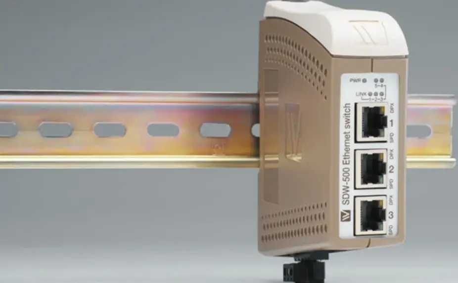
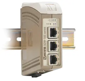
The SDW-550 is an Industrial Ethernet 5-port switch.
All ports support auto-negotiation, but DIP-switches also allow speed and duplex configuration of any individual TX port. It is also possible to set up one port to monitor traffic to/from the switch.
The SDW-550 has been designed to meet high industrial specifications, providing very high dependability in harsh environmental conditions.
Features
- TX shields individually isolated
- Wide DC power range 12 – 48 VDC
- Wide temperature range
- Automatic MDI/MDI-X crossover
- LED indicators for Power, Speed, Duplex, Link and Traffic … Port monitoring
- 35 mm DIN rail mounting
- Enable or disable of flow control
Example of applications are:
- 5-port switch
- Ethernet isolator, for STP networks
Interface specifications
| Power SDW-500 series | |||
| Rated voltage | 12 –48 VDC, polarity protected | ||
| Operating voltage | 9.6 – 57.6 VDC | ||
| Rated current | @12 VDC power input | ||
| SDW-550 | 320 | mA | |
| SDW-541-MM-SC2 | 450 | mA | |
| SDW-541-SM-LC15 | 450 | mA | |
| SDW-541-SM-SC15 | 350 | mA | |
| SDW-541-MM-LC2 | 350 | mA | |
| SDW-532-MM-SC2 | 600 | mA | |
| SDW-532-SM-LC15 | 450 | mA | |
| SDW-532-SM-SC15 | 450 | mA | |
| SDW-532-SM-LC40 | 450 | mA | |
| SDW-532-MM-LC2 | 450 | mA | |
| Rated frequency | DC | ||
| Connection | Detachable screw terminal | ||
| Connector size | 0.2 – 2.5 mm² (AWG 24-12) | ||
| Ethernet TX | |
| Electrical specification | IEEE std 802.3. 2000 edition |
| Data rate | 10 Mbit/s or 100 Mbit/s, manual or auto |
| Duplex | Full or half, manual or auto |
| Connection | SC, ST or LC |
| Circuit type | Optical |
| Transmission range | 100 m |
| Ethernet FX | |
| Electrical specification | IEEE std 802.3. 2000 edition |
| Data rate | 10 Mbit/s or 100 Mbit/s, manual or auto |
| Duplex | Full or half, manual or auto |
| Connection | SC, ST or LC |
| Circuit type | Optical |
| Transmission range | 100 m |
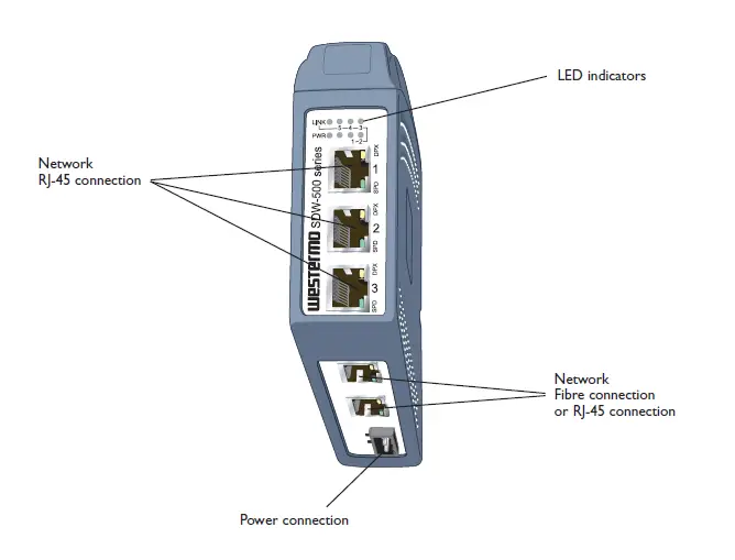
Connections
Available models:
- SDW-550 10/100Base-T/TX: 5 ports
- SDW-541 10/100Base-T/TX: 4 ports 100Base-FX: 1 port
- SDW-532 10/100Base-T/TX: 3 ports 100Base-FX: 2 ports
Power
The SDW-500 series supports redundant power connection. The positive input are +VA and +VB, the negative input for both supplies are COM.
The power is drawn from the input with the highest voltage.
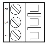
| 3-pos screw terminal | Description | Power |
| 1 | COM | 0 V |
| 2 | +VA | A: 9.6 – 57.6 VDC |
| 3 | +VB | B: 9.6 – 57.6 VDC |
TX
Ethernet TX connection (RJ-45 connector), automatic MDI/MDI-X crossover.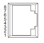
| Contact | Signal Name | Direction | Description/Remark |
| 1 | TD+ | In/Out | Transmitted/Received data |
| 2 | TD– | In/Out | Transmitted/Received data |
| 3 | RD+ | In/Out | Transmitted/Received data |
| 4 | – | – | – |
| 5 | – | – | – |
| 6 | RD– | In/Out | Transmitted/Received data |
| 7 | – | – | – |
| 8 | – | – | – |
| Shield | – | – | HF-connected |
CAT 5 cable is recommended.
Unshielded (UTP) or shielded (STP) connector might be used.
FX SC Multi- or single mode (optional)
Ethernet FX connection.
1300 nm multi- or singlemode fibre tranceiver with SC-connector.
The dust protection plug shall be mounted when no fibre is connected.
FX ST Multi mode (optional)
Ethernet FX connection.
1300 nm multi mode fibre tranceiver with ST-connector.
The dust protection plugs shall be mounted when no fibre is connected.
FX LC Multi- or single mode (optional)
Ethernet FX connection.
1300 nm singlemode fibre transceiver with LC-connector.
The dust protection plug shall be mounted when no fibre is connected.
LED indicators
At power on the PWR flashes during initialising.
Indicators (LED) Power (PWR)
Link (LINK) of every port
Speed (SPD) and duplex (DPX) of TX ports
| LED | Status | Indication of |
| PWR | ON | Internal power, initialising OK |
| Slow flash | Initialisation progressing | |
| Fast flash | Initialisation error | |
| LINK | OFF | No Ethernet link |
| ON | Good Ethernet link | |
| Flash | Ethernet data is transmitted or received, traffic indication | |
| SPD | OFF | 10 Mbit/s |
| (TX only) | ON | 100 Mbit/s |
| DPX | OFF | Half duplex |
| (TX only) | ON | Full duplex |
Installation
Mounting / Remova
HAZARDOUS VOLTAGE
Do not open an energized product. Hazardous voltage may occur when connected to a power supply.
ELECTROSTATIC DISCHARGE (ESD)
Prevent electrostatic discharge damages to internal electronic parts by discharging your body to a grounding point (e.g. use a wrist strap).
Mounting
This product should be mounted on 35 mm DIN-rail which is horizontally mounted on a wall or cabinet backplate. l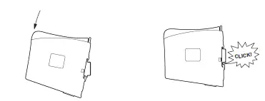
Cooling
This product uses convection cooling.
To avoid obstructing the airflow around the product, use the following spacing rules. Minimum spacing 25 mm (1.0 inch) above / below and 10 mm (0.4 inches) left / right the product.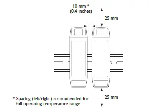
Spacing is recommended for the use of product in full operating temperature range and service life.
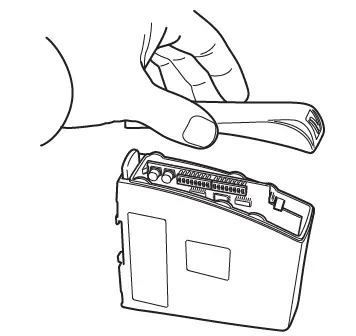
Removal Press down the black support at the back of the product, see figure.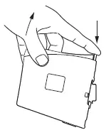
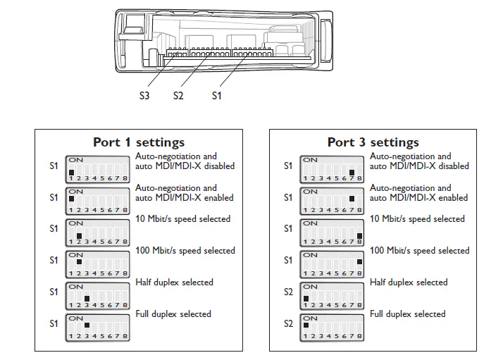
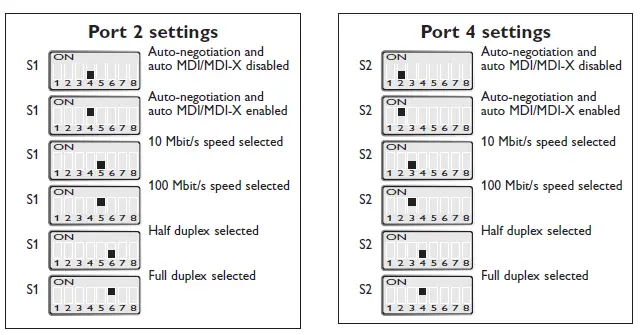
DIP switch settings SDW-550
DIP-switches are accessible under the lid on top of the product. DIP-switches are used to configure the product.
HAZARDOUS VOLTAGE
Do not open an energized product. Hazardous voltage may occur when connected to a power supply.
ELECTROSTATIC DISCHARGE (ESD)
Prevent electrostatic discharge damages to internal electronic parts by discharging your body to a grounding point (e.g. use a wrist strap).
NOTE
When configuration via DIP-switches, the settings of DIP-switches configure the product only after a reboot (power off/on).
Observe this when the DIP-switches are configured:
- Speed and duplex setting only valid when auto-negotiation is disabled.
- When monitoring selected all outgoing packets from the switch is also copied to the port 1.
- Speed and duplex switch settings are ignored for FX ports.
- If auto-negotiation and auto MDI/MDI-X disabled all TX ports support MDI-X configuration.
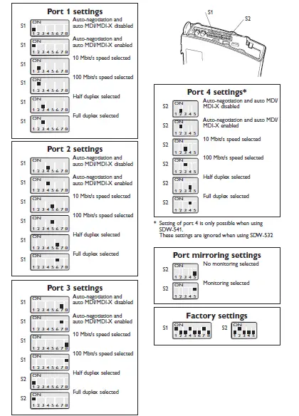
DIP switch settings SDW-541 and SDW-532
DIP-switches are accessible under the lid on top of the product. DIP-switches are used to configure the product.
HAZARDOUS VOLTAGE
Do not open an energized product. Hazardous voltage may occur when connected to a power supply.
ELECTROSTATIC DISCHARGE (ESD)
Prevent electrostatic discharge damages to internal electronic parts by discharging your body to a grounding point (e.g. use a wrist strap).
NOTE
When configuration via DIP-switches, the settings of DIP-switches configure the product only after a reboot (power off/on).
Observe this when the DIP-switches are configured:
- Speed and duplex setting only valid when auto-negotiation is disabled.
- When monitoring selected all outgoing packets from the switch is also copied to the port 1.
- Speed and duplex switch settings are ignored for FX ports.
- If auto-negotiation and auto MDI/MDI-X disabled all TX ports support MDI-X
Westermo • Metallverksgatan 6, SE-721 30 Västerås, Sweden Tel +46 16 42 80 00 Fax +46 16 42 80 01
E-mail: [email protected]
www.westermo.com
REV. J 6644-2214 2023-02 Westermo Network Technologies AB, Sweden


