![]() Lynx 5600 Series
Lynx 5600 Series
Industrial Gigabit switch
User Guide![]()
General Information
1.1. Legal Information
The contents of this document are provided “as is”. Except as required by applicable law, no warranties of any kind are made in relation to the accuracy and reliability or contents of this document, either expressed or implied, including but not limited to the implied warranties of merchantability and fitness for a particular purpose. Westernmost reserves the right to revise this document or withdraw it at any time without prior notice.
Under no circumstances shall Westernmost be responsible for any loss of data or income or any special, incidental, and consequential or indirect damages howsoever caused.
More information about Westernmost can be found at www.westermo.com.
1.2. About This Guide
This guide is intended for installation engineers and users of the Westernmost products.
It includes information on safety and regulations, a product description, installation instructions and technical specifications.
1.3. Software Tools
Related software tools are available at https://www.westermo.com/support/productsupport.
1.4. License and Copyright for Included FLOSS
This product includes software developed by third parties, including Free/Libre Open Source Software (FLOSS). The specific license terms and copyright associated with the software are included in each software package respectively. Please visit the product web page for more information.
Upon request, the applicable source code will be provided. A nominal fee may be charged to cover shipping and media. Please direct any source code request to your normal sales or support channel.
1.5. We OS
This product runs We OS 5 (Westernmost Operating System). Instructions for quick start, configuration and factory reset are found in the We OS user documentation at www.westermo.com.
Safety and Regulations
2.1. Warning Levels
Warning signs are provided to prevent personal injuries and/or damages to the product.
The following levels are used:
| Level of warning | Description | Consequence personal injury | Consequence material damage |
| Indicates a potentially hazardous situation | Possible death or major injury | Major damage to the product |
| Indicates a potentially hazardous situation | Minor or moderate injury | Moderate damage to the product |
| Provides information in order to avoid misuse of the product, confusion or misunderstanding | No personal injury | Minor damage to the product |
| Used for highlighting general, but important information | No personal injury | Minor damage to the product |
 CAUTION
Table 1. Warning levels
2.2. Safety Information
Before installation:
Read this manual completely and gather all information available on the product. Make sure it is fully understood. Check that your application does not exceed the safe operating specifications for the product.![]() SAFETY DURING INSTALLATION
SAFETY DURING INSTALLATION
The product must be installed and operated by qualified service personnel and installed into an apparatus cabinet or similar, where access is restricted to service personnel only.
Refer to chapter Compliance Information to see the required level of qualified service personnel according to safety standards.
Before energising and connecting communication cables to the product, ensure a protective earthing conductor is first connected to the protective earthing terminal (only valid for metallic housings). Westermo recommends a cross-sectional area of at least 4 mm2 .
Upon removal of the product, disconnect the product from the power supply and all other communication ports before disconnecting the protective earthing conductor.![]() HAZARDOUS VOLTAGE
HAZARDOUS VOLTAGE
Do not open an energized product. Hazardous voltage may occur when connected to a power supply.![]() PROTECTIVE FUSE
PROTECTIVE FUSE
It must be possible to disconnect manually from the power supply. Ensure compliance to national installation regulations.
Replacing the internal fuse must only be performed by Westernmost qualified personnel.![]() POWER SUPPLY CONNECTION
POWER SUPPLY CONNECTION
There are safety regulations governing the power source that can be used in conjunction with the product. Refer to chapter Interface Specifications.![]() REDUCE THE RISK OF FIRE
REDUCE THE RISK OF FIRE
To reduce the risk of fire, use only telecommunication line cords with a cable diameter of AWG 26 or larger. Regarding power cable dimensions, see chapter Interface Specifications.![]() HOT SURFACE
HOT SURFACE
Be aware that the surface of this product may become hot. When it is operated at high temperatures, the external surface may exceed Touch Temperature Limit according to the product’s relevant electrical safety standard.![]() CLASS 1 LASER PRODUCT
CLASS 1 LASER PRODUCT
Do not look directly into a fibre optical port or any connected fibre, although the product is designed to meet the Class 1 Laser regulations and complies with 21 CFR 1040.10 and 1040.11.![]() HANDLING OF SFP TRANSCEIVERS
HANDLING OF SFP TRANSCEIVERS
SFP transceivers are supplied with plugs to avoid contamination inside the optical port. They are very sensitive to dust and dirt. If the fibre optic cable is disconnected from the product, a protective plug must be used on the transmitter/receiver. The protective plug must be kept on during transportation. The fibre optic cable must be handled the same way.![]() CORROSIVE GASES
CORROSIVE GASES
If the product is placed in a corrosive environment, it is important that all unused connector sockets are protected with a suitable plug, in order to avoid corrosion attacks on the gold plated connector pins.![]() ELECTROSTATIC DISCHARGE (ESD)
ELECTROSTATIC DISCHARGE (ESD)
Prevent electrostatic discharge damage to internal electronic parts by discharging your body to a grounding point (e.g. use a wrist strap).![]() CABLE TEMPERATURE RATING FOR FIELD TERMINAL WIRES
CABLE TEMPERATURE RATING FOR FIELD TERMINAL WIRES
There may be a requirement on the minimum temperature rating of the cable to be connected to the field wiring terminals, see chapter Interface Specifications.
2.3. Care Recommendations
Follow the care recommendations below to maintain full operation of the product and to fulfill the warranty obligations:
- Do not drop, knock or shake the product. Rough handling above the specification may cause damage to internal circuit boards.
- Use a dry or slightly water-damp cloth to clean the product. Do not use harsh chemicals, cleaning solvents or strong detergents.
- Do not paint the product. Paint can clog the product and prevent proper operation.
If the product is used in a manner not according to specification, the protection provided by the equipment may be impaired.
If the product is not working properly, contact the place of purchase, the nearest Westernmost distributor office or Westernmost technical support.
2.4. Product Disposal
This symbol means that the product shall not be treated as unsorted municipal waste when disposing of it. It needs to be handed over to an applicable collection point for recycling electrical and electronic equipment.
By ensuring the product is disposed of correctly, you will help to reduce hazardous substances and prevent potential negative consequences to both the environment and human health, which could be caused by inappropriate disposal.![]() Figure 1. WEEE symbol for treatment of product disposal
Figure 1. WEEE symbol for treatment of product disposal
2.5. Compliance Information
2.5.1. Agency Approvals and Standards Compliance
| Type | Approval/Compliance |
| EMC | • EN/IEC 61000-6-1, Immunity residential environments • EN/IEC 61000-6-2, Immunity industrial environments • EN/IEC 61000-6-3, Emission residential environments • EN/IEC 61000-6-4, Emission industrial environments • EN/IEC 61000-6-5, Immunity power station and substation environments • IEC 61850-3, Communication networks and systems for power utility automation – Part 3: General requirements |
| Environmental | • NEMA TS 2, Traffic Controller Assemblies with NTCIP Requirements • AREMA |
| Safety | • EN/IEC/UL 61010-1, -2-201, Safety requirements for electrical equipment for measurement, control, and laboratory use |
| Track side | • EN 50121-4/IEC 62236-4, Railway signalling and telecommunications apparatus |
| Marine | • DNV GL rules for classification – Ships and offshore units |
Table 2. Agency approvals and standards compliance
2.5.2. EN/IEC/UL 61010-2-201 Notice
This product has been tested and found compliant to EN/IEC/UL 61010-2-201, Safety requirements for electrical equipment for measurement, control, and laboratory use. In accordance with the definitions of the standard, this product shall be handled by skilled service personnel.
2.5.3. IEC 61850-3 Notice
This product has been tested according to IEC 61850-3. Standalone, this product meets the requirements stated in the standard for protected area.
When combined with Westernmost PS-60, this product meets the requirements applicable to power stations and M-substations. The product is defined as a reliability class 1 product.
For SA applications, the product must be powered with 24 to 48 VDC.
2.5.4. EN 61000-6-5 Notice
This product has been tested according to EN 61000-6-5 and is compliant to Interface type 4 requirements. The DC port has tested as signal port and is not intended to be connected to DC distribution network.
For SA applications, the product must be powered with 24 to 48 VDC.
2.5.5. NAME TS2
The product has been third party tested according to The National Electrical Manufacturers Association (NAME) TS2, including pass of high temperature tests in 74°C.
Please note that the product is specified for long-term operation in maximum 70°C.
2.5.6. FCC Part 15.105 Class B Notice
This product has been tested and found to comply with the limits for a Class B digital device, pursuant to Part 15 of the FCC Rules. These limits are designed to provide reasonable protection against harmful interference in a residential installation. This product
generates, uses and can radiate radio frequency energy and, if not installed and used in accordance with the instructions, may cause harmful interference to radio communications.
However, there is no guarantee that interference will not occur in a particular installation.
If this product does cause harmful interference to radio or television reception, which can be determined by turning the product off and on, the user is encouraged to try to correct the interference by one or more of the following measures:
- Reorient or relocate the receiving antenna
- Increase the separation between the unit and receiver
- Connect the product into an outlet on a circuit different from that to which the receiver is connected
- Consult the dealer or an experienced radio/TV technician for help
2.5.7. Corrosive Environment
This product has been successfully tested in a corrosion test according to IEC 60068-2-60, method 3. This means that the product meets the requirements to be placed in an environment classified as ISA-S71.04 class G3.![]() CORROSIVE GASES
CORROSIVE GASES
If the product is placed in a corrosive environment, it is important that all unused connector sockets are protected with a suitable plug, in order to avoid corrosion attacks on the gold plated connector pins.
2.5.8. Simplified Declaration of Conformity
Hereby, Westernmost declares that this product is in compliance with applicable EU directives and UK legislation. The full declaration of conformity and other detailed information is available at www.westermo.com/support/product-support.

Figure 2. The European Conformity and the UK Conformity Assessment markings
Product Description
3.1. Product Description
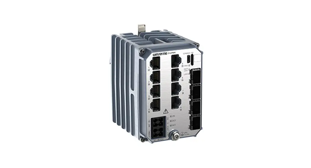
The Lynx 5612 is a high-performance substation automation-approved Ethernet switch ideal for energy and substation automation applications.
It is the most compact high-performance switch for energy systems on the market. It has been developed with the needs of current and future networks in mind. Combining outstanding performance, durability and reliability, it is ideal switch for handling big data and high bandwidth requirements.
Critical energy infrastructure cannot tolerate interruptions of service which is why the switch is engineered to maintain uninterrupted data communication even in exceptionally harsh environments. Lynx-5612 has been tested and verified to withstand extreme
temperatures, vibrations and EMI aligned with IEC 61850-3 Ed.2
Furthermore only industrial grade components are used which contributes towards a market leading mean time between failure (MTBF), maximized service life and reduced operational and life cycle costs.
By providing full gigabit speed on all 12 ports, four flexible SFP ports and layer 2 and layer 3 functionality, a broad range of applications are possible. Powered by the next generation WeOS operating system, which ensures robust operation and support for an expanding range of protocols and features. In addition, recognizing the growing sophistication of cyberattacks, an extensive suite of cyber security tools is available.
The switches support IEEE 1588v2 PTP time synchronization, ideal for real-time applications. In addition, they are prepared for hardware accelerated routing and hardware cybersecurity features, making them the ideal solution to meet future security and bandwidth requirements.
3.2. Available Models
| Art. no. | Model | Gigabit TX ports | Gbit SFP ports | SW | Rated voltage |
| 3643-0400 | Lynx 5612-F4G-T8G-LV | 8 | 4 | L2 | 12-48 VDC |
| 3643-0405 | Lynx-5612-E-F4G-T8G-LV | 8 | 4 | L3 | 12-48 VDC |
3.3. Hardware Overview
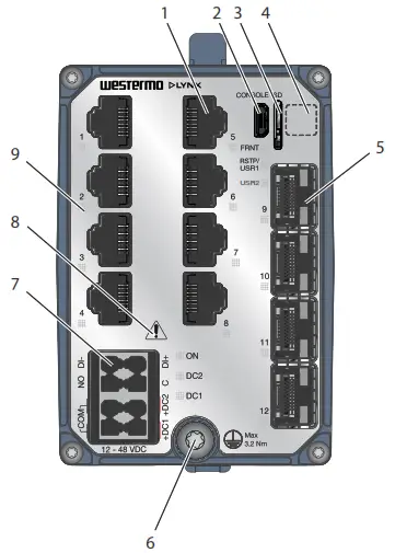
Figure 4. Location of interface ports and LED indicators
| No. | Description | No. | Description |
| 1 | Gigabit ports | 2 | Console port |
| 3 | Micro SD | 4 | Label with data matrixa. |
| 5 | Gigabit SFP Ports | 6 | Protective earth terminal |
| 7 | Power Input and I/O connection | 8 | Warning symbol, see warning in Power Input and I/O Connection [12] |
| 9 | LED indicators |
a. The base MAC address and production date of the product is included in the front label data matrix.
Figure 3. Location of interface ports and LED indicators
3.4. Connector Information
3.4.1. Power Input and I/O Connection
| Illustration | Position | Product marking | Direction | Description |
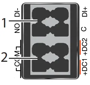 | 1 – I/O connection | DI+ | Input | Digital in positive |
| DI- | Input | Digital in negative | ||
| C | Output | Relay output common | ||
| NO | Output | Relay output normally open | ||
| 2 – Power input | +DC1 | Input | DC1 positive | |
| +DC2 | Input | DC2 positive | ||
| COM | Input | Common | ||
| COM | Input |
Table 3. Power input and I/O connection
| Unit condition | Status NO- C |
| Powered / per-operational or Alarm active | OPEN |
| Operational and Alarm inactive | CLOSED |
Table 4. I/O connection status output
POWER SUPPLY CONNECTION
There are safety regulations governing the power source that can be used in conjunction with the product. Refer to chapter Interface Specifications.
3.4.2. Console Port
The console port can be used to connect to the CLI (Command Line Interface). The console connector is a USB cable that connects to a FTDI FT232R USB to serial converter internally. For drivers, refer to www.ftdichip.com and download the appropriate VCP
driver.
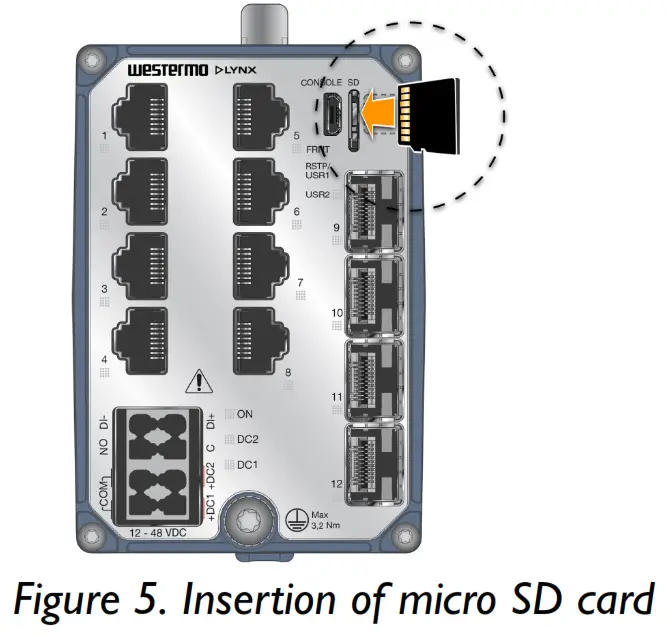
3.4.3. Micro SD
To insert the micro SD card correctly, turn the gold plated pins to the left side.
3.4.4. SFP Transceivers
Each SFP slot can hold one SFP transceiver. See “Transceiver User Guide 6100-0000” for transceiver handling instructions, which also can be downloaded from the product support pages at www.westermo.com/support/product-support.
In the event of contamination, the optical connectors in the SFP transceivers should only be cleaned by the use of forced nitrogen and some kind of cleaning stick. Recommended cleaning fluids are methyl-, ethyl-, isopropyl- or isobutyl alcohol, hexane or naphtha.![]() HANDLING OF SFP TRANSCEIVERS
HANDLING OF SFP TRANSCEIVERS
SFP transceivers are supplied with plugs to avoid contamination inside the optical port. They are very sensitive to dust and dirt. If the fibre optic cable is disconnected from the product, a protective plug must be used on the transmitter/receiver. The protective plug must be kept on during transportation. The fibre optic cable must be handled the same way.
3.5. LED Indicators
| LED | Status | Description |
| ON | OFF | Product has no power |
| GREEN | All OK, no alarm condition | |
| RED | Alarm condition, or until product has started up. (Alarm conditions are configurable, see WeOS5 User Guide) | |
| BLINK | Location indicator (“Here I am!”). Activated when connected to WeConfig tool, or upon request from web or/and CLI. RED BLINK during boot indicates pending cable factory reset. | |
| RSTP/ USR1 | Configurable, see WeOS5 User Guide | |
| FRNT | OFF | FRNT disabled |
| GREEN | FRNT OK | |
| RED | FRNT error | |
| FLASH | Product configured as FRNT focal point | |
| DC1 | OFF | Product has no power |
| GREEN | Power OK on DC1 | |
| RED | +DC1 input voltage is below operating voltage limit | |
| DC2 | OFF | Product has no power |
| GREEN | Power OK on DC2 | |
| RED | +DC2 input voltage is below operating voltage limit | |
| USR2 | Configurable, see WeOS5 User Guide | |
| TX/FX ports | OFF | No link |
| GREEN | Link established | |
| GREEN FLASH | Data traffic indication | |
| YELLOW | Port alarm and no link. Or if FRONT or ERST mode, port is blocked. | |
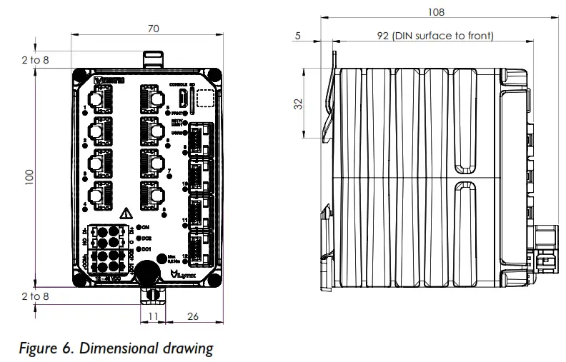
3.6. Dimensions
Dimensions are stated in mm and are regardless of model.
Installation
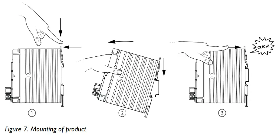
4.1. Mounting
This product should be mounted on a 35 mm DIN-rail, which is horizontally mounted inside an apparatus cabinet or similar. The DIN-rail must be connected to ground.
- To mount the product, first push the support pin down, then towards the front of the product to lock the support pin.
- Then, place the product on to the DIN-rail. First the upper part, then the lower part of the product.
- Lastly, push the support pin forward to lock the product to the DIN-rail. Make sure the products is secured to the DIN-rail.
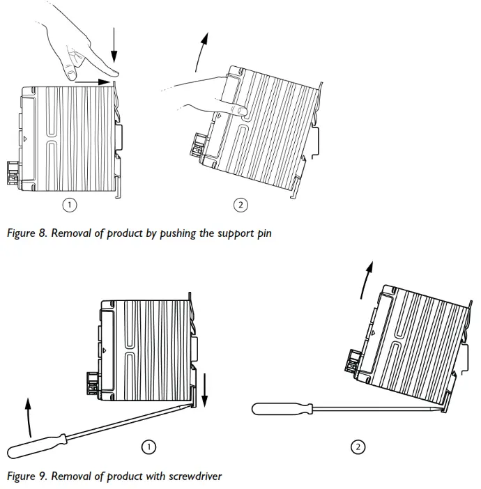
4.2. Removal of Product
To remove the product either push the support pin down and towards the front of the product, or press down the support at the back with a screwdriver, and lift off the product from the DIN-rail.
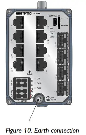
4.3. Protective Earth Connection
For correct function, the earth connection needs to be properly connected to a designated PE rail. Torx: T25 and torque: 3.2 Nm.
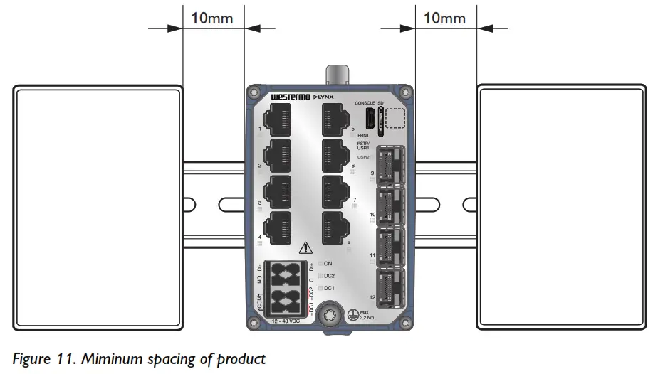
4.4. Cooling
This unit uses convection cooling. To avoid obstructing the airflow around the unit, use the following spacing rules. Minimum spacing 25 mm (1.0 inch) above / below and 10 mm (0.4 inches) left / right the unit. Spacing is recommended for the use of unit in full operating temperature range and service life.
![]() REDUCE THE RISK OF FIRE
REDUCE THE RISK OF FIRE
To reduce the risk of fire, use only telecommunication line cords with a cable diameter of AWG 26 or larger. Regarding power cable dimensions, see chapter Interface Specifications.
Specifications
5.1. Interface Specifications
| DC, Power port | ||
| Rated voltages. | 12-48 VDC, Class III (SELV/PERV) | |
| Operating voltage | 9.6-60 VDC | |
| Rated current | 1.7 A at 12 VDC 0.67 A at 24 VDC 0.35 A at 48 VDC | |
| Fuse rating Component: U2 | Denote time-delay fuse | 4A(T) |
| Rated frequency | DC | |
| Inrush current, I²tb. | 0.087 A2s at 12 VDC 0.137 A2s at 24 VDC 0.400 A2s at 48 VDC | |
| Startup current | 2x nominal current | |
| Polarity | Reverse polarity protected | |
| Redundant power input | Yes | |
| Isolation | All other ports | |
| Connector | Detachable push-in terminal | |
| Conductor cross section (flexible) | 0.2-1.5 mm² (AWG 24-16). Use copper conductors only. | |
| Stripping length cable | 10 mm | |
| Cable temperature rating | For minimum temperature rating of the cable to be connected to the field wiring terminals: + 90 °C | |
| Circuit type | SELV | |
| Shielded cable | Not required | |
a. CE-compliant Class I or Class II power supplies with SELV/PELV output shall be used with the product
b. Measured for 1 second at startup
| I/O connection, Digital inputa. | |
| Isolation to | All other ports |
| Connector | Detachable push-in terminal |
| Conductor cross section | 0.2 -1.5 mm² (AWG 24 – 16). Use copper conductors only. |
| Stripping length cable | 10 mm |
| Circuit type | SELV |
| Maximum voltage/current | 60 VDC, IIN ≤ 2.9 mA at 60 VDC |
| Voltage levels | Logic one: >8 VDC Logic zero: <5 VDC |
a. External circuits connected to I/O connectors shall be SELL-rated circuits, galvanic isolated from mains.
| I/O connection, Relay outputs. | |
| Type of switch | Solid state, DC general use |
| Connect resistance | Maximum 30 Ω |
| Isolation to | All other ports |
| Connector | Detachable push-in terminal |
| Conductor cross section | 0.2-1.5 mm² (AWG 24-16). Use copper conductors only. |
| Stripping length cable | 10 mm |
| Circuit type | SELV |
| Maximum voltage/current | 60 VDC/80 mA |
External circuits connected to I/O connectors shall be SELL-rated circuits, galvanic isolated from mains.
| Ethernet TXa. | |
| Electrical specification | IEEE std 802.3 |
| Data rate | 10 Mbit/s, 100 Mbit/s, 1000 Mbit/s, manual or auto |
| Duplex | Full or half, manual or auto |
| Circuit type | SELV according to EN/IEC/UL 61010-2-201 TNV-1 according to IEC 62151 |
| Transmission range | Up to 100 m with CAT5e cable or better |
| Isolation | All other ports |
| Cabling | Shielded cable CAT5e or better is recommended |
| Conductive chassis | Yes |
a. 10/100/1000 Mbit/s ports are no. 1 to 8
| SFP portsa. | |
| Optical/Electrical specification | IEEE std 802.3 |
| Data rate | 100 Mbit/s, 1000 Mbit/sb. |
| Duplex | Full or half, manual or auto |
| Transmission range | Depending on transceiver |
| Connector | SFP slot holding fibre transceiver |
a. SFP ports are 9 to 12
b. 100 Mbit/s or 1000 Mbit/s transceiver supported
| Console porta. | |
| Electrical specification | USB 2.0 device interface |
| Data rate | Up to 480 Mbps (high-speed mode) |
| Circuit type | SELV |
| Maximum supply current | 100 mA |
| Connector | USB Micro B connector in device mode |
a. External circuits connected to I/O connectors shall be SELL-rated circuits, galvanic isolated from mains.
| Micro SD | |
| Electrical specification | Secure Digital 2.0 |
| Circuit type | SELV |
| Maximum supply current | 100 mA |
| Connector | Micro SD connector |
5.2. Type Tests and Environmental Conditions
| Environmental phenomena | Basic standard | Description | Test levels |
| ESD | EN 61000-4-2 | Enclosure | Contact: ±8 kV Air: ±15 kV |
| Fast transients | EN 61000-4-4 | AC power porta. | ± 2 kV, 5 and 100 kHz, direct coupling |
| DC power port | ± 4 kV, 5 and 100 kHz, direct coupling | ||
| Earth port | |||
| I/O port | ± 4 kV, 5 and 100 kHz, capacitive coupling clamp | ||
| Ethernet ports | |||
| Surge | EN 61000-4-5 | AC power porta. | L-E: ± 4 kV, 12 Ω, 9 µF, 1.2/50 µs L-L: ± 2 kV, 2 Ω, 18 µF, 1.2/50 µs |
| DC power port | L-E: ± 1 kV, 12 Ω, 9 µF, 1.2/50 µs L-E: ± 2 kV, 42 Ω, 0.5 µF, 1.2/50 µs L-L: ± 0,5 kV, 2 Ω, 18 µF, 1.2/50 µs L-L: ± 1 kV, 12 Ω, 9 µF, 1.2/50 µs L-L: ± 1 kV, 42 Ω, 0,5 µF, 1.2/50 µs | ||
| I/O port | L-E, L-L: ± 1 kV, 12 Ω, 9 µF, 1.2/50 µs L-E: ±2 kV, 42 Ω, 0.5 µF, 1.2/50 µs L-L: ±1 kV, 42 Ω, 0.5 µF, 1.2/50 µs | ||
| Ethernet ports | L-E: ± 4 kV, 2 Ω, Direct on shield, 1.2/50 µs | ||
| Power frequency magnetic field | EN 61000-4-8 | Enclosure | 300 A/m continues, DC, 16.7, 50, 60 Hz 1000 A/m 10 s, 50, 60 Hz |
| Pulsed magnetic field | EN 61000-4-9 | Enclosure | 300 A/m |
| Damped oscillatory magnetic field | EN 61000-4-10 | Enclosure | 30 A/m (peak) |
| Conducted CM disturbances | EN 61000-4-16 | DC power port | 30 V rms to 3 V rms, 15 to 150 Hz 3 V rms, 150 Hz to 1.5 kHz 3 V rms to 10 V rms, 1.5 to 15 kHz 30 V rms, 15 to 150 kHz |
| I/O port | |||
| Ethernet ports | |||
| Mains frequency voltage | EN 61000-4-16 | DC power port | 30 V rms continuous, DC, 16.7, 50 and 60 Hz, 300 V rms for 1 s |
| I/O port | |||
| Ethernet ports | |||
| Ripple on DC power supply | EN 61000-4-17 | DC power port | 10% of UN, 33.3, 100 and 120 Hz, 10 min |
| Damped oscillatory wave | EN 61000-4-18 | AC power porta. | CM: ±2.5 kV 200 Ω/0.5 µF, 1 MHz CM: ±1 kV 50 Ω/0.5 µF, 10 MHz DM: ±1.5 kV, 200 Ω/0.5 µF, 1 MHz |
| DC power port | CM: ±2.5 kV 200 Ω/0.5 µF, 1 MHz CM: ±2 kV 50 Ω/0.5 µF, 10 MHz DM: ±2.5 kV 200 Ω/0.5 µF, 1 MHz |
| Environmental phenomena | Basic standard | Description | Test levels |
| I/O port | CM: ±2.5 kV 200 Ω/0.5 µF, 1 MHz DM: ±2.5 kV 200 Ω/0.5 µF, 1 MHz | ||
| Ethernet ports | CM: ±2.5 kV 200 Ω, 1 MHz, Direct on shield | ||
| Voltage dips and interruptions (AC port) | EN 61000-4-11 | AC power porta. | 70 % UT, 1 period 40 % UT, 50 periods 0 % UT, 5 periods |
| Radiated RF immunity | EN 61000-4-3 IEEE Std C37.90.2 | Enclosure | 20 V/m, 80% AM (1kHz) at 80 MHz to 2,7 GHz, spot freq.: 80, 160, 380, 450, 900, 1600, 1850 MHz 10 V/m, 80% AM (1 kHz) at 2.7 to 6 GHz, spot freq.: 2150, 3800 MHz 20 V/m, pulse keying (2 Hz) at 80 MHz to 1 GHz, spot freq.: 1732, 1800 MHz 10 V/m, pulse keying (2 Hz), spot freq.: 2310, 2450, 5800 MHz 20 V/m, PM 200 Hz square at 900 MHz |
| Conducted RF immunity | EN 61000-4-6 | AC power porta. | 10 V/m, 0.15 to 80 MHz, spot freq.: 2, 3, 4,6.2, 8.2, 12.6, 16.5, 18.8, 22, 25 MHz |
| DC power port | |||
| Ethernet ports | |||
| I/O port | |||
| Earth port | |||
| Radiated RF emission | CISPR 16-2-3 | Enclosure | Class B (Residential), 30 MHz to 6 GHz DNV-CG – Bridge and Deck Zone, 0.15 to 2000 MHz FCC Part 15 B, Class B, 30 MHz to 20.5 GHz |
| DNV-CG-0339 | |||
| ANSI C63,4 | |||
| Conducted RF emission | CISPR 16-2-1 | DC power port | Class B (Residential), 0.15 to 30 MHz |
| DIV-CG – Bridge and Deck Zone, 10 kHz to 30 MHz | |||
| Ethernet ports | Class B (Residential), 0.15 to 30 MHz | ||
| Compass safe distance | IEC 60945 | Enclosure | Minimum safe distance to: standard compass: 25 cm steering compass: 20 cm |
| Power supply failure | DNV-CG-0339 | DC power port | UN-100%, 30 s |
| Power supply variation | 1.3 x UN (62.4 VDC), 0.75 x UN (18 VDC), 15 min | ||
| Immunity to conducted low frequency interference | 3 Vrms, 0.05 to 10 kHz |
| Environmental phenomena | Basic standard | Description | Test levels |
| Insulation resistance | DNV-CG-0339 | Power port (DC) to all other ports | 500 VDC, 60 s |
| I/O port to all other ports | |||
| IEEE 802.3 | Ethernet ports to all other ports | ||
| Dielectric strength | IEC 60255-27 | AC power port to secondary DC aides. | 2000 VAC ems, 60 s |
| Power port (DC) to all other ports | 1500 VAC ems, 60 s | ||
| I/O port to all other ports | |||
| IEEE 802.3 | Ethernet ports to all other ports | ||
| Impulse withstand | IEC 60255-27 | AC power port to secondary DC aides. | 5 kV |
| IEEE 802.3 | Ethernet ports to all other ports | 2.4 kV |
a. In combination with PS-60
Table 6. EMC and electrical conditions
| Environmental phenomena | Basic standard | Description | Test levels |
| Temperatures | EN 60068-2-1 EN 60068-2-2 EN 60068-2-14 | Operational | -40 to +70°C (-40 to +158°F)a. |
| Storage and transport | -55 to +85°C (-67 to +185°F) | ||
| Humidity | EN 60068-2-30 EN 60068-2-78 | Operational | 5-95 % relative humidity +25/40°C, 93/98 % RH, cyclic 6 days +40 °C, 93 % RH, steady state 10 days |
| Storage and transport | |||
| Device reliability class | IEC 61850-3 | Class 1: Temporary loss of communication and/or communication errors can be tolerated | |
| IEEE 1613 | |||
| Corrosive gases | IEC 60068-2-60 | Operational | Method 3, 21 daysb. |
| Altitude | Operational | 2000 m/80 kPa | |
| MTBF | MILKMAID 217F | 506,000 hours | |
| Cordelia | 955,000 hours | ||
| Vibration. | IEC 60068-2-6 (sine) | Operational | 5 to 20 Hz, 1,3 mm 20 to 200 Hz, 1 g 20 sweep cycles in each axis, 1 octave/min |
| Class 2, 10 to 150 Hz at 2 g 20 sweep cycles in each axis, 1 octave/min | |||
| 5 to 8 Hz at ± 7.5 mm 8 to 500 Hz at 2 g 5 sweep cycles in each axis (3 x 5), 1 octave/min | |||
| Non-operational, resonance test | 2 to 13.2 Hz at ± 1 mm 13.2 to 100 Hz at 1 g 1 sweep cycle in each axis, 1 octave/min | ||
| IEC 60068-2-64 (random) | Operational | 2.3 m/s2 random, 5 to 2000 Hz, 3 x 1.5 h | |
| Operational, endurance test | 1 g random, 2-100 Hz, 3 x 150 min | ||
| Shock. | IEC 60255-21-2 | Operational | Class 2, 30g/11ms, 3 x 6 shocks (half sine) |
| IEEE 1478 | 200 m/s2, 11 ms, 3 x 6 shocks (saw tooth) | ||
| Bump. | IEC 60255-21-2 | Operational | Class 2, 20g/16 rms, 6 x 1000 bumps |
| Enclosure | EN 61010-1 | Aluminium | Fire enclosure |
| Weight | 690 gr | ||
| Degree of protection | EN 60529 | Enclosure | IP40 |
| Cooling | Convection |
| Environmental phenomena | Basic standard | Description | Test levels |
| Over voltage category | EN/IEC/UL 61010-1 | OVA II | |
| Pollution degree | EN/IEC/UL 61010-1, EN 50124-1 | PD2 macro and micro environment | |
| Location | EN/IEC/UL 61010-1 | Indoor |
a. Refer to “Safety and Regulations” chapter regarding touch temperature
b. Method 3, 21 days corresponds to Harsh Industrial Environment G3 which is defined in ANSI/ISA 17.04: 2015
c. The power and I/O cables need to be fastened 200 mm or closer to the unit. The same recommendation applies to the Ethernet cables.
Table 7. Environmental and mechanical conditions
Revision Notes
| Revision | Date | Change description |
| Rev. H | 2023-05 | DIV approval added |
| Rev. G | 2023-02 | 1.3 Software Tools updated, 2.2 Safety Information; warning Safety during installation updated, 2.5.1 Agency Approvals and Standards Compliance updated (UL 62368-1 deleted), 2.5.3 IEC 61850-3 Notice updated, old 2.5.5. ARENA deleted, 3.1 Product Description updated (footnote removed for “features”, 3.3 Hardware Overview; table updated (data matrix), 3.4.2 Console Port; text updated, 3.5 LED Indicators updated (WeOS5 User Guide and BLINK > FLASH), 4.3 Protective Earth Connection; Torx added, 5.2 Type Tests and Environmental Conditions updated |
| Rev. F | 2022-01 | 2.2 Safety Information updated (Warning – Safety during installation), 2.5.2 EN/IEC/UL 61010-2-210 Notice added, 5.2 Type Tests and Environmental Conditions updated (UL added to EN/IEC 61010-1) |
| Rev. E | 2021-12 | 3.1 Product Description updated (text), 5.1 Interface Specifications updated (DC Power port) |
| Rev. D | 2021-06 | 2.5.1 Agency Approvals and Standards Compliance: UL added to EN/IEC 61010-1, -2-201, 2.5.3 IEC 61850-3 Notice updated, 2.5.4 EN 61000-6-5 Notice updated, 5.1 Interface Specifications updated |
| Rev. C | 2021-06 | DIV approval removed |
| Rev. B | 2021-01 | 2.5.4 NAME TS2 new chapter, 5.1 Interface Specifications, DC Power port updated (cable temperature rating), 5.2 Type Tests and Environmental Conditions updated (temperature range updated). |
| Rev. A | 2020-09 | First revision |
![]() Westernmost
Westernmost
Metallurgical 6, SE-721 30 Vorster, Sweden
Tel +46 16 42 80 00 Fax +46 16 42 80 01
E-mail: [email protected]
www.westernmost.com
6643-25002 REV H 2023 05 @ Westernmost Network Technologies AB, Sweden


