![]()
USER GUIDE
Merlin 4400 Series
Industrial Cellular Router
General Information
Legal Information
The contents of this document are provided “as is”. Except as required by applicable law, no warranties of any kind are made in relation to the accuracy and reliability or contents of this document, either expressed or implied, including but not limited to the implied warranties of merchantability and fitness for a particular purpose. Westermo reserves the right to revise this document or withdraw it at any time without prior notice.
Under no circumstances shall Westermo be responsible for any loss of data or income or any special, incidental, and consequential or indirect damages howsoever caused.
More information about Westermo can be found at www.westermo.com.
About This Guide
This guide is intended for installation engineers and users of the Westermo products.
It includes information on safety and regulations, a product description, installation instructions and technical specifications.
License and Copyright for Included FLOSS
This product includes software developed by third parties, including Free/Libre Open Source Software (FLOSS). The specific license terms and copyright associated with the software are included in each software package respectively. Please visit the product web page for more information.
Upon request, the applicable source code will be provided. A nominal fee may be charged to cover shipping and media. Please direct any source code request to your normal sales or support channel.
Safety and Regulations
Warning Levels
Warning signs are provided to prevent personal injuries and/or damages to the product. The following levels are used:
| Level of warning | Description | Consequence personal injury | Consequence material damage |
| Indicates a potentially hazardous situation | Possible death or major injury | Major damage to the product | |
| Indicates a potentially hazardous situation | Minor or moderate injury | Moderate damage to the product | |
| Provides information in order to avoid misuse of the product confusion or misunderstanding | No personal injury | Minor damage to the product | |
| Used for highlighting general, but important information | No personal injury | Minor damage to the product |
Table 1. Warning levels
Safety Information
Before installation:
Read this manual completely and gather all information available on the product. Make sure it is fully understood. Check that your application does not exceed the safe operating specifications for the product.
![]() SAFETY DURING INSTALLATION
SAFETY DURING INSTALLATION
The product must be installed and operated by qualified service personnel and installed into an apparatus cabinet or similar, where access is restricted to service personnel only. During installation, ensure a protective earthing conductor is first connected to the protective earthing terminal (only valid for metallic housings). Westermo recommends a cross-sectional area of at least 4 mm2. Upon removal of the product, ensure that the protective earthing conductor is disconnected last.
![]() HAZARDOUS VOLTAGE
HAZARDOUS VOLTAGE
Do not open an energised product. Hazardous voltage may occur when connected to a power supply.
![]() PROTECTIVE FUSE
PROTECTIVE FUSE
The power supply wiring must be sufficiently fused. It must be possible to disconnect manually from the power supply. Ensure compliance to national installation regulations. This product has no internal fuse and should be connected via an external fuse for protection.
![]() POWER SUPPLY CONNECTION
POWER SUPPLY CONNECTION
There are safety regulations governing the power source that can be used in conjunction with the product. Refer to chapter Interface Specifications.
![]() REDUCE THE RISK OF FIRE
REDUCE THE RISK OF FIRE
To reduce the risk of fire, use only telecommunication line cords with a cable diameter of AWG 26 or larger. Regarding power cable dimensions, see chapter Interface Specifications.
![]() RADIO PRODUCTS
RADIO PRODUCTS
Observe the usage limitations of radio products at filling stations, in chemical plants, in systems with explosives or potentially explosive locations.
The product may not be used in airplanes. Exercise particular caution near personal medical aids, such as pacemakers and hearing aids. Never perform work on the antenna system during a thunderstorm.
To fulfill human safety, a minimum separation distance of 20 cm or more should be maintained between the antenna of the product and personnel during operation.
![]() ELECTROSTATIC DISCHARGE (ESD)
ELECTROSTATIC DISCHARGE (ESD)
Prevent electrostatic discharge damage to internal electronic parts by discharging your body to a grounding point (e.g. use a wrist strap).
![]() HOT SURFACE
HOT SURFACE
Be aware that the surface of this product may become hot. When it is operated at high temperatures, the external surface may exceed Touch Temperature Limit according to the product’s relevant electrical safety standard.
![]() CABLE TEMPERATURE RATING FOR FIELD TERMINAL WIRES
CABLE TEMPERATURE RATING FOR FIELD TERMINAL WIRES
There may be a requirement on the minimum temperature rating of the cable to be connected to the field wiring terminals, see chapter Interface Specifications.
Care Recommendations
Follow the care recommendations below to maintain full operation of the product and to fulfill the warranty obligations:
- Do not drop, knock or shake the product. Rough handling above the specification may cause damage to internal circuit boards.
- Use a dry or slightly water-damp cloth to clean the product. Do not use harsh chemicals, cleaning solvents or strong detergents.
- Do not paint the product. Paint can clog the product and prevent proper operation.
If the product is used in a manner not according to specification, the protection provided by the equipment may be impaired.
If the product is not working properly, contact the place of purchase, the nearest Westermo distributor office or Westermo technical support.
Product Disposal
This symbol means that the product shall not be treated as unsorted municipal waste when disposing of it. It needs to be handed over to an applicable collection point for recycling electrical and electronic equipment. By ensuring the product is disposed of correctly, you will help to reduce hazardous substances and prevent potential negative consequences to both the environment and human health, which could be caused by inappropriate disposal.
![]()
Figure 1. WEEE symbol for treatment of product disposal
Compliance Information
Agency Approvals and Standards Compliance
| Type | Approval/Compliance |
| EMC | • EN/IEC 61000-6-2, Immunity industrial environments • EN/IEC 61000-6-4, Emission industrial environments • EN 50121-4, Railway signalling and telecommunications apparatus (pending) • IEC 61850-3, Communication networks and systems for power utility automation – Part 3: General requirements |
| Safety | • EN 62368-1, Safety Communication Technology |
Table 2. Agency approvals and standards compliance
Simplified Declaration of Conformity
Hereby, Westermo declares that this product is in compliance with applicable EU directives and UK legislations. The full declaration of conformity and other detailed information is available at www.westermo.com/support/product-support.
![]()
Figure 2. The European Conformity and the UK Conformity Assessment markings
Product Description
Product Description
The Merlin 4400 series of versatile cellular routers is designed from the ground up to achieve best-in-class Cybersecurity both in hardware and software. A TPM chip (Trusted Platform Module) keeps cryptographic keys secure. Secure Boot guarantees that the unit boots using only software that is signed and trusted by Westermo. A set of cybersecurity tools is available as standard. High security VPNs, stateful inspection firewall, user authentication and 802.1x are just a few of the features available to keep the device secure both locally and when transmitting data over the internet or private network.
Legacy serial (RS-232/485) ports allow the Merlin 4400 to be used in applications where it is necessary to migrate from modems to an IP infrastructure. The built-in industrial protocol gateway enables several devices using different protocols to be accessed via a common protocol interface.
The Merlin 4400, like all the members of the Merlin family, is compatible with the Activator zero-touch deployment software. The Activator software ensures that configurations are generated and deployed from a central server, reducing configuration mistakes and increasing efficiency during the installation phase of a project.
This compact unit is suited to tight spaces. Its high MTBF, wide temperature range and voltage supply ensure the Merlin can deal with the demands of industrial, smart grid and trackside applications.
Available Models
| Art.no. | Product | Ethernet | Serial | TPM | Region |
| 3460-44100 | Merlin-4407-T4-S2-LV-QFZ | 4 | 2 | Yes | EMEA |
| 3460-44200 | Merlin-4407-T4-S2-LV-PFJ | 4 | 2 | Yes | Australia |
Hardware Overview
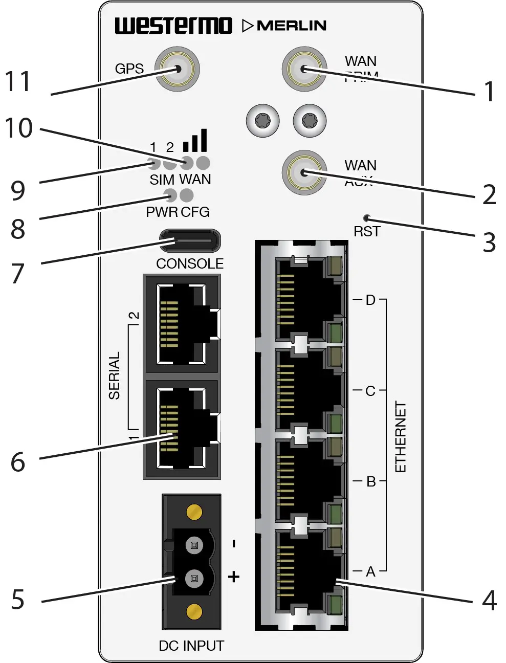
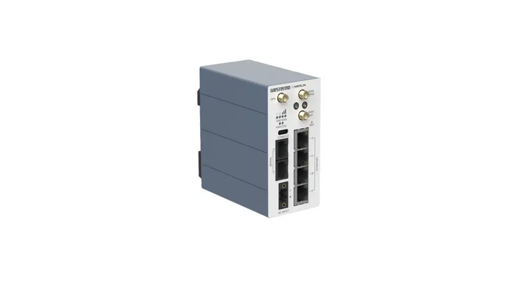
Figure 3. Location of interface ports and LEDs, illustrated by a Merlin-4407-T4-S2-LV model
| No. | Description | No. | Description |
| 1 | WAN primary SMA connector | 2 | WAN auxiliary SMA connector |
| 3 | Reset button | 4 | Ethernet RJ45 ports |
| 5 | Power connection | 6 | Serial ports |
| 7 | USB-C Console port | 8 | Power and configuration LEDs |
| 9 | SIM LEDs | 10 | WAN signal strength |
| 11 | GPS SMA connector |
Connector Information Merlin
Power Input
| Illustration | Position | Product marking | Direction | Description |
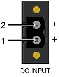 | 1 | DC+ | Input | Supply voltage |
| 2 | DC- | Input | Supply voltage |
Table 3. Power input
The positive input is marked with a plus sign, “+”. The negative input is marked with a minus sign, “-“. Connect the voltage to the + pin and the return to the – pin on the power input.
![]() NOTICE – POWER SUPPLY
NOTICE – POWER SUPPLY
Where an AC/DC-adapter has not been supplied, a power supply of no greater than 100 W should be used, with a current limit of 1 Amp.
Serial Ports
A pair of asynchronous serial ports may be present on the router.
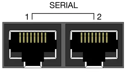
Figure 4. Serial ports
Serial port 1 operates in RS-232 mode. Serial port 2 is configurable to operate in either RS-232 or RS-485 mode.
The pin numbering of the serial port connector, when viewed from the front of the unit, is shown below.
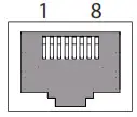 Figure 5. Pin numbering of serial port
RS-232 ports
When you configure a serial port to operate as an RS-232 interface, it supports the following signals:
- Transmit Data
- Receive Data
- CTS
- RTS
- DSR
- DTR
The pin numbering of the RJ45 socket, when viewed from the front of the unit, is as shown below. The RS-232 interface is wired as a DCE and the pinout is shown below.
| Illustration | Pin no. | Signal | Direction | Description |
| 1 | DSR | Out | Data Set Ready |
| 2 | DCD | Out | Data Carrier Detect | |
| 3 | DTR | In | Data Terminal Ready | |
| 4 | SG | – | Signal Ground, not chassis ground | |
| 5 | RD | Out | Receive Data | |
| 6 | TD | In | Transmit Data | |
| 7 | CTS | Out | Clear To Send | |
| 8 | RTS | In | Request To Send |
Table 4. RS-232 connection
RS-485 ports
When you configure a serial port to operate as an RS-485 interface, it supports both two-wire (half-duplex) and four-wire (full-duplex) modes. Configuration between two-wire and four-wire RS-485 modes is under software control. The pin-numbering of the RJ45 connector in RS-485 mode, when viewed from the front of the unit, is shown below.
| Illustration | Pin no. | Signal | Direction | Description | |
| Four-wire mode | Two-wire mode | ||||
| 1 | ||||
| 2 | R- | – | In | Four wire: Receive | |
| 3 | T- | T-/R- | Out/In | Four-wire: Transmit Two-wire: Transmit/Receive | |
| 4 | |||||
| 5 | R+ | In | Four-wire: Receive | ||
| 6 | T+ | T+/R+ | Out/In | Four-wire: Transmit Two-wire: Transmit/Receive | |
| 7 | |||||
| 8 | |||||
Table 5. RS-485 port pinout
Console Port
The router has a USB console port with a type C connector. The router acts as a device.
Antennas
The router has three SMA connectors. They are:
- Two LTE antennas for the mobile radio – a MAIN and an AUXiliary
- Single antenna for GNSS/GPS
Use the reset button to request a system reset. When pressing the reset button, all LEDs turn on simultaneously. The length of time holding the reset button will determine its behaviour.
| Press duration | PWR/CONFIG LED behaviour | Router behaviour on depress |
| 0-3 seconds | Solid on | Normal reset to running config. No special LED activity. |
| 3-15 seconds | Flashing fast | Releasing 3-15 seconds switches the router back to factory configuration. Note: this will wipe the configurations, both config1 and config2. |
| 15-20 seconds | Solid on | Releasing 15-20 seconds performs a normal reset to running config. |
| 20-30 seconds | Flashing slowly | Releasing 20-30 seconds reboots the router to recovery mode. Only to be done in case of emergency and under the guidance of Westermo support staff. Note: this may wipe the configurations, both config1 and config2. |
| > 30 seconds | Solid on | Releasing after 30 seconds performs a normal reset. |
Table 6. Merlin series router reset behaviour
LED Indicators
The LED indicators described in this section are all single colour LEDs. When the router is powered on, the power LED is green.
The possible LED states are:
- Off
- Flashing slowly
- Flashing quickly
- On
| LED | Status | Description |
| Booting up | The router takes less than a minute to boot up. During this time, the power LED flashes. Other LEDs display different diagnostic patterns during boot up. Booting is complete when the power LED stops flashing and stays on steady. | |
| Power | On | Power is present |
| Off | No power. Boot loader does not exist. | |
| Flashing | Booting | |
| Config | On | The router is running a valid configuration file. |
| Flashing slowly | The router is running in recovery mode (2.5 flashes/second) | |
| Flashing quickly | The router is running in factory configuration (5 flashes/second) | |
| SIM | On | SIM selected and registered on the 3G/4G network |
| Off | Not selected or SIM not inserted | |
| Flashing | SIM selected and not registered on the network | |
| 3G/L1E cellular signal strength LED | Both LEDs off | Data link not connected or signal strength <=-113 dBm |
| Left LED on Right LED off | Data link connected and signal strength <=89 dBm | |
| Left LED off Right LED on | Data link connected and signal strength is between -89 to -69 dBm | |
| Both LEDs on | Data link connected and signal strength >-69 dBm |
Table 7. LED indicators
Ethernet Port LED Behaviour
There are four Ethernet ports and each has a pair of LEDS: a LINK LED (green) and a SPEED LED (amber). When looking at the port, the LED on the bottom is the LINK LED, and the SPEED LED is on the top.
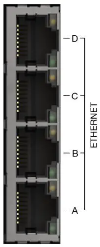
Figure 6. Merlin 4400 Ethernet ports
| LINK LED (green) | On | Physical Ethernet link detected |
| Off | No physical Ethernet link detected | |
| Flashing | Data is being transmitted or received over the link | |
| SPEED LED (amber) | On | Link operating at 100 Mbps |
| Off | Link operating at 10 Mbps |
Table 8. Ethernet LED behaviour and descriptions
Dimensions
Dimensions are stated in millimetres and are regardless of model.
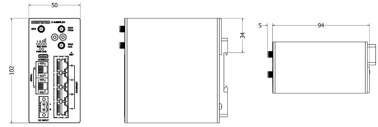
Figure 7. Dimensional drawing
Installation
Mounting the Router
The router is fitted with a DIN-rail clip by default. To attach the router to a DIN-rail:
- Position the router so that the spring of the DIN-clip rests on the DIN-rail.
- Push the router in an upward direction so that the spring of the DIN-clip compresses and the top hook of the DIN-clip slides and clamps to the DIN-rail.
To remove the router from the DIN-rail, simply reverse the procedure.
![]() MOUNTING HEIGHT
MOUNTING HEIGHT
To reduce the risk of personal injury and damage to the device, the unit must not be mounted at a height greater than two metres above the ground beneath it.
Cooling
This product uses convection cooling. Spacing is recommended for the use of the product in full operating temperature range and service life. To avoid obstructing the airflow around the product, use the following spacing rules. Minimum spacing of 25 mm (1 inch) above/below and 10 mm (0.4 inches) left/right of the product is recommended.
![]() REDUCE THE RISK OF FIRE
REDUCE THE RISK OF FIRE
To reduce the risk of fire, use only telecommunication line cords with a cable diameter of AWG 26 or larger. Regarding power cable dimensions, see chapter Interface Specifications.
Connecting Cables
Connect one end of the Ethernet cable into port A and the other end to your PC or switch.
Connecting the Antenna
If only connecting one LTE antenna, screw the antenna into the MAIN SMA connector. If you are using more than one LTE antenna, screw the main antenna into the MAIN SMA connector and the secondary antenna into the WAN-AUX SMA connector.
Inserting SIM Cards
On the rear side of the router there are two SIM slots. To access the SIM cards, first remove the SIM cover using a Torx driver (Torx-10). Only the proper driver can drive a specific head size without risk of damaging the driver or screw.
Inserting SIM 1 Card
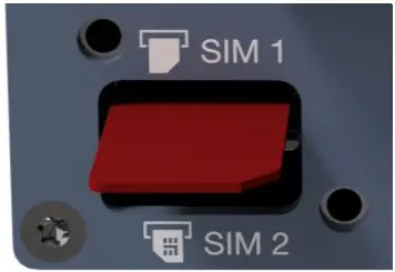
Figure 8. Inserting SIM card into SIM 1 slot
Ensure the router is powered off.
- Remove the SIM cover using a Torx 10 driver
- Hold the SIM 1 card with the chip side facing down and the cut corner facing towards you, to the right
- Gently push the SIM card into the upper SIM slot 1 until it is fully inserted
- Screw the SIM cover back on with the Torx 10 driver
Inserting SIM 2 Card
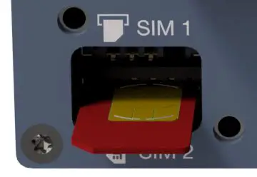
Figure 9. Inserting SIM card into SIM 2 slot
- If you are using a second SIM, hold the SIM 2 card with the chip side facing up and the cut corner facing towards you, to the left
- Gently push the SIM card into the lower SIM slot 2 until it is fully inserted
- Screw the SIM cover back on with the Torx driver
Powering Up
Plug the power cable into an electrical socket suitable for the power supply. The router takes less than a minute to boot up. During this time, the power LED flashes.
Other LEDs display different diagnostic patterns during boot up. Booting is complete when the power LED stops flashing and stays on steady.
Specifications
Interface Specifications
DC, Power port
| Operating voltage | 9.6 to 60 VDC |
| Rated current | 325 mA at 12 VDC 103 mA at 48 VDC |
| Rated frequency | DC |
| Inrush current | 2.74 x 10⁻³ A2 at 12 VDC |
| Polarity | Reverse polarity protected |
| Redundant power input | No |
| Isolation | All other ports |
| Connector | Push-in spring connectors |
| Conductor cross section | 0.2-2.5 mm² (AWG 24-12) |
| Stripping length cable | 7 mm |
| Tightening torque, screw flange | 0.3 Nm |
| Shielded cable | Not required |
Ethernet TX
| Electrical specification | IEEE std 802.3 |
| Data rate | 10 Mbit/s, 100 Mbit/s, manual or auto |
| Duplex | Full or half, manual or auto |
| Circuit type | TNV-1 |
| Transmission range | Up to 150 m with CAT5e cable or better |
| Isolation | All other ports |
| Connection | RJ-45, auto MDI/MDI-X |
| Cabling | Shielded CAT5e or better is recommended |
| Number of ports | 4 |
RS-232/485
| Electrical specification | Configurable for EIA RS-232 or EIA RS-422/485 |
| Data rate | RS-232: 50 bit/s – 1 Mbit/s |
| RS-485: 50 bit/s – 12 Mbit/s | |
| Data format | 7 or 8 data bits, odd, even or none parity, 1 or 2 stop bits (2 stop bits only when no parity is set) |
| Circuit type | TNV-1 |
| Transmission range | RS-232: 15 m/49 ft |
| RS-485: Up to 1200 m/0.74 mi, depending on data rate and cable type | |
| Number of ports | Up to 2 |
| Connection | RJ-45 according to EIA-561 |
| RJ-45 shielded cable |
Console port
| Electrical specification | USB 2.0 host interface |
| Data rate | 115.2 kbit/s |
| Circuit type | SELV |
| Data format | 8 data bits, no parity, 1 stop bit, no flow control |
| Connection | USB receptacle connector type C |
Type Tests and Environmental Conditions
| Environmental phenomena | Basic standard | Description | Test levels |
| ESD | EN 61000-9-2 | Enclosure | Contact *6 kV Air: ±8 kV |
| Fast transients | EN 61000-9-4 | Power port | * 9 kV. direct couplire |
| Ethernet ports | * 9 kV. capacitive coupling clamp | ||
| Earth | |||
| Serial ports | |||
| Sucre | EN 61000-9-5 | Power port | L-E: ±2 kV. 12 Ω. 9 μF. 1.2/50 μs L-E: ± 2 kV. 42 Ω. 0.5 μF. 1.2/50 μs L-L ±1 kV. 2 Ω. 18 μF. 1.2/50 μs L-L ± 1 kV. 42 Ω. 0.5 μF. 1.2/50 μs |
| Ethernet ports | L-E: ± 2 kV. 2 Ω direct on shield. 12/50 μs | ||
| RS-232 | L-E: ± 2 kV. 2 Ω 0.5 μF | ||
| R5-922/985 | L-E: ± 2 kV. 42 Ω. 0.5 μF | ||
| Pomer frequency magnetic field | EN 61000-9-8 | Enclosure | 100 A/m: 50 Hz |
| Radiated PF Immunity | EN 61000-9-3 | Enclosure | 20 V/m at 800 MHz to 1 GHz 10 V/m at 80 MHz to 3 GHz 5 V/m at 2.7 GHz to 6 GHz 1 kHz sine. 80% AM |
| Conducted RE emission | EN 61000-9-6 | Power port | 10 V. 80% AM. 1 kHz 0.15 MHz to 80 MHz |
| Ethernet | |||
| Serial ports | |||
| Earth | |||
| Radiated RF emission | EN 55032. EN 61000-6-4 | Enclosure | 30 MHz to 12 GHz |
| Conducted RF embsim | EN 55032. EN | Power port | 150 kl-lz to 30 MHz |
| 61000-6-4 | Ethernet | 150 Id-lz to 30 MHz | |
| Dielectric strength | UL 62368-1 | Power port to all other ports | 15 kVDC. 1 min |
| UL 62368-1 IEEE 8013 | Ethernet TX to all other ports | 15 kVrms. 50 Hz 1 min |
Table 9. EMC and electrical conditions
| Environmental enomena lith | Basic standard | Description | Test levels |
| Temperatures | EN 60068-2-1 EN 60068-2-2 | Operational | -40 to +70°C (-40 to +158°F)a |
| Humidity | EN 60068-2-30 | Operational | 5-95% relative humidity |
| MTBF | Telcordia | Ground benign, 25°C | 1,600,000 hours |
| Enclosure | EN 62368-1 | Aluminium | Fire enclosure |
| Weight | 0.5 kg | ||
| Cooling | Convection |
aRefer to “Safety Information” chapter regarding touch temperature
Table 10. Environmental and mechanical conditions
Revision Notes
| Revision | Date | Change description |
| Rev. B | 2022-03-29 | First version |
| Rev. C | 2022-05-26 | Revised product codes in the section ‘Available Models’. Corrected descriptions of points 9 and 10 in section ‘Hardware Overview’. |
| Rev. D | 2022-11-18 | Revised artwork and metrics |
![]() Westermo • Metallverksgatan 6, SE-721 30 Vasteras, Sweden
Westermo • Metallverksgatan 6, SE-721 30 Vasteras, Sweden
Tel +46 16 42 80 00 Fax +46 16 42 80 01
E-mail: [email protected]
www.westermo.com
EN_REV D 2022 11 @ Westermo Network Technologies AB, Sweden


