westermo BRD-355A Industrial ADSL/VDSL Routers User Guide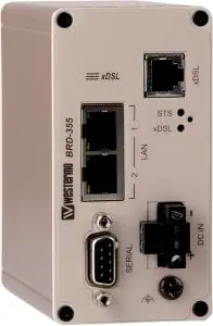
General information
Legal information
The contents of this document are provided “as is”. Except as required by applicable law, no warranties of any kind, either express or implied, including, but not limited to, the implied warranties of merchantability and fitness for a particular purpose, are made in relation to the accuracy and reliability or contents of this document. Westermo reserves the right to revise this document or withdraw it at any time without prior notice.
Under no circumstances shall Westermo be responsible for any loss of data or income or any special, incidental, and consequential or indirect damages howsoever caused.
More information about Westermo can be found at www.westermo.com
Safety and Regulations
Warning signs are provided to prevent personal injuries and/or damages to the product. The following levels are used:
Level of warning | Description | Consequence personal injury | Consequence material damage |
| Indicates a potentially hazardous situation | Possible death or major injury | Major damage to the product |
| Indicates a potentially hazardous situation | Minor or moderate injury | Moderate damage to the product |
| Provides information in order to avoid misuse of the product, confusion or misunderstanding | No personal injury | Minor damage to the product |
| Used for highlighting general, but important information | No personal injury | Minor damage to the product |


Before installation:
Read this manual completely and gather all information on the product. Make sure that you understand it fully. Check that your application does not exceed the safe operating specifications for this product.
 WARNING – SAFETY DURING INSTALLATION
The product must be installed by qualified service personnel and built in to an apparatus cabinet or similar, where access is restricted to service personnel only.
During installation, ensure a protective earthing conductor is first connected to the protective earthing terminal (only valid for metallic housings). Westermo recommends a cross-sectional area of at least 4 mm2.
If the product does not have a protective earthing terminal, then the DIN-rail must be connected to protective earth. Upon removal of the product, ensure that the protective earthing conductor, or the connection to earth via the DIN-rail, is disconnected last.
WARNING – HAZARDOUS VOLTAGE
Do not open an energized product. Hazardous voltage may occur when connected to a power supply.
WARNING – PROTECTIVE FUSE
It must be possible to disconnect manually from the power supply. Ensure compliance to national installation regulations. Replacing the internal fuse must only be performed by Westermo qualified personal.
WARNING – POWER SUPPLY CONNECTION
There are safety regulations on which power sources that shall be used in conjunction with the product. Refer to Interface Specifications.
WARNING – REDUCE THE RISK OF FIRE
To reduce the risk of fire, use only telecommunication line cords with a cable diameter of AWG 26 or larger. Regarding power cable dimensions, see Interface Specifications.
 CAUTION – ELECTROSTATIC DISCHARGE (ESD)
Prevent electrostatic discharge damages to internal electronic parts by discharging your body to a grounding point (e.g. use a wrist strap).
CAUTION – CABLE TEMPERATURE RATING FOR FIELD TERMINAL WIRES
There may be a requirement on the minimum temperature rating of the cable to be connected to the field wiring terminals, see Interface Specifications.
Care recommendations
Follow the care recommendations below to maintain full operation of product and to fulfill the warranty obligations:
- Do not drop, knock or shake the product. Rough handling above the specification may cause damage to internal circuit boards.
- Use a dry or slightly water-damp cloth to clean the product. Do not use harsh chemicals, cleaning solvents or strong detergents.
- Do not paint the product. Paint can clog the product and prevent proper operation.
If the product is used in a manner not according to specification, the protection provided by the equipment may be impaired.
If the product is not working properly, contact the place of purchase, nearest Westermo distributor office or Westermo technical support.
Product disposal
 This symbol means that the product shall not be treated as unsorted municipal waste when disposing of it. It needs to be handed over to an applicable collection point for recycling electrical and electronic equipment.
By ensuring this product is disposed of correctly, you will help to reduce hazardous substances and prevent potential negative consequences to both environment and human health, which could be caused by inappropriate disposal.
Simplified EU declaration of conformity
Hereby, Westermo declares that the product is in compliance with applicable EU directives. The full EU declaration of conformity and other detailed information is available at the respective product page at www.westermo.com/support/productsupport.
Agency approvals and standards compliance
| Type | Approval / Compliance |
EMC | EN 55032, Multimedia equipment, Emission Requirements |
| EN 55035, Multimedia equipment, Immunity Requirements | |
Safety | EN 62368-1, Safety Communication Technology |
EN 62368-1
Notice:
This product has been tested and found compliant to EN 62368-1, Safety for Communication Technology. In accordance with the definitions of the standard, this product shall be handled by skilled personell. Energy source classifications are according to following:
Electrical energy source | Power port | ES1 |
| Serial port | ES1 | |
| Ethernet port | ES1 | |
Power source | Power port | PS3 |
Thermal energy source | Enclosure | TS1 |
Mechanical energy source | Enclosure | MS1 |
Radiation energy source | SFP | Not applicable |
Type tests and environmental conditions
Phenomena | Test | Description | Test levels |
ESD | EN 61000-4-2 | Enclosure contact | ± 6 kV (crit B) |
| Enclosure air | ± 8 kV (crit A) | ||
Radiated RF immunity | IEC 61000-4-3 | Enclosure | 20 V/m (crit A) (80 – 6000 MHz) |
Fast transient | EN 61000-4-4 | DC power ports | ± 2 kV (crit B) |
| Ethernet ports | ± 2 kV (crit B) | ||
| Serial port | ± 2 kV (crit B) | ||
| xDSL ports | ± 2 kV (crit B) | ||
Surge | EN 61000-4-5 | DC power ports | ± 2 kV (crit B), 42 Ω ± 500 V (crit A), 12 Ω |
| Ethernet ports | ± 4 kV (crit B), (shielded cable) | ||
| xDSL ports | ± 4 kV (crit B) | ||
RF conducted | EN 61000-4-6 | DC power ports | 10 V/m, (crit A), (0.15 – 80 MHz) |
| Ethernet ports | 10 V/m, (crit A), (0.15 – 80 MHz) 10 V/m, (crit B), (0.15 – 80 MHz) | ||
| xDSL ports | 10 V/m (crit A), (0.15 – 80 MHz) 10 V/m (crit B), (0.15 – 80 MHz) | ||
Radiated emission | CISPR 16-2-3 | Enclosure | EN 61000-6-3 |
Conducted emission | CISPR 16-2-1 | DC power ports | EN 61000-6-3 |
| CISPR 32 | Ethernet ports | ||
| xDSL port | |||
Dialectric strenght | EN 62368-1 IEEE 802.3 | Power port to all other ports | 1.5 kVrms, 50 Hz, 1 min |
| Signal port to all other ports | |||
| xDSL port to all other ports | |||
Temperature | EN 60068-2-1 EN 60068-2-2 | Operating | –25 to +70°C (–13 to +158°F) |
| Storage & Transport | –40 to +85°C (–40 to +185°F) | ||
Humidity | EN 60068-2-30 | Operating | 0 to 90% relative humidity non condensing. |
| Storage & Transport | 0 to 90% relative humidity non condensing. | ||
Altitude | Operating | 2000 m / 70 kPa | |
Service life | Operating | 10 years | |
Dimension W x H x D | 53 x 103 x 97 mm (2.08 x 4.05 x 3.81 in) | ||
Weight | 0.40 kg | ||
Degree of protection | IEC 529 | Enclosure | IP 40 |
Cooling | Convection | ||
Mounting | Horizontal on 35 mm DIN-rail |
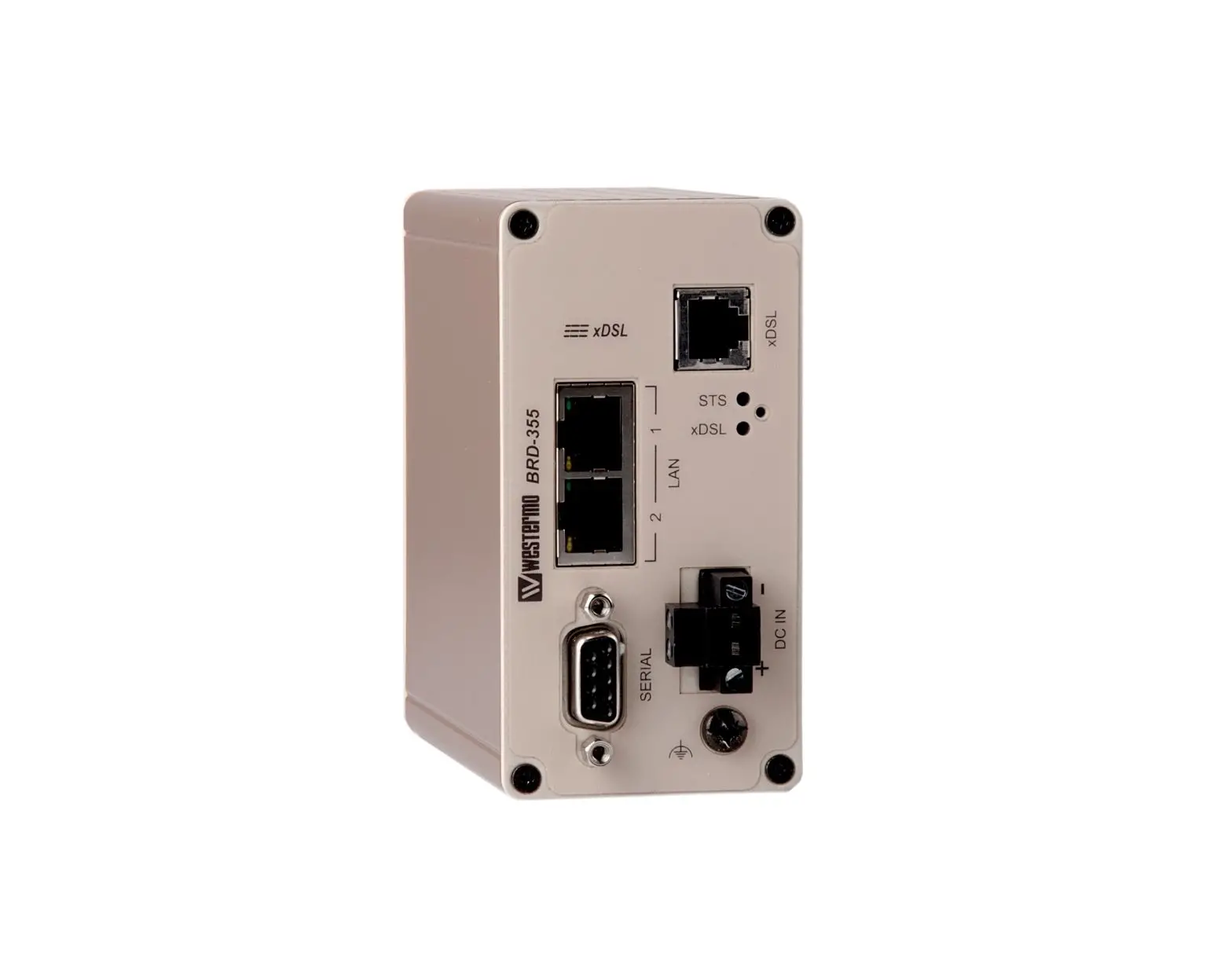
Description
Remote access removes boundaries, eliminates the need for time consuming site visits and provides a network infrastructure suitable for today’s “always-on” society. The BRD355 is an industrially designed xDSL (ADSL/VDSL2) broadband router built to cope with harsh environments and the characteristics of industrial applications. The unit supports a wide range of xDSL-standards and has support for long lines.
Most devices today comes equipped with an Ethernet port for communications, therefore the BRD-355 has a built-in two port Ethernet switch. For legacy connectivity the unit also features one RS-232-port to provide multiple connection possibilities for both new and legacy replacement installations. Designed to be installed on a DIN-rail all connectors and LEDs have been positioned in the front of the unit, facing the user for easy access and fast status feedback. With wide power input range, the unit can be powered from 10 to 60 VDC and has low power consumption.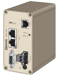
The cybersecurity features of the BRD-355 prevent unauthorized access and secure the communication for Internet-enabled applications. The easy to use firewall filters incoming traffic, allowing only approved packets to pass through. To inter-connect units with each other securely over the Internet multiple VPN technologies are supported, including IPsec and OpenVPN.
Upgrading legacy solutions to become IP-enabled can prove both costly and tedious therefore the BRD-355 includes a wide feature set for various legacy applications including both modem replacement methods as well as serial to Ethernet conversion. If there are applications that require extra attention Westermo’s extensive experience from over 35 years within industrial data communications and over 5 years of industrial xDSL expertise will be available to assist you.
Interface specifications
Power | |
| Rated voltage | 12 – 48 VDC |
| Operating voltage | 10 – 60 VDC |
| Operational current (max) | 450 mA @ 12 VDC |
| Rated current (max) | 1000 mA @ 12 VDC |
| Rated frequency* | DC |
| Startup current | 2 x rated current |
| Circuit type | SELV/ES1 |
| Cable size | 0.2-2.5 mm² (AWG 24-12) |
| Cable temperature rating | For minimum temperature rating of the cable to be connected to the field wiring terminals: -25 to + 70 °C |
| Isolation | To all other ports |
*Recommended external supply current capability for proper startup
RS-232 | |
| Electrical specification | EIA RS-232 |
| Data rate | 300 bit/s – 115.2 kbit/s |
| Data format | 7 or 8 data bits, Odd, even or none parity, 1 or 2 stop bits |
| Protocol | Transparent, optimised by packing algorithm |
| Circuit type | SELV/ES1 |
| Transmission range | 15 m / 49 ft |
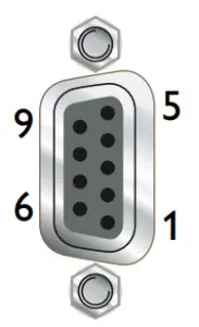
| Connection | 9 pin D-sub female |
| Shielded cable | Not required |
| Conductive housing | Yes |
| Number of ports | 1 |
Ethernet TX | |
| Electrical specification | IEEE std 802.3. 2005 Edition |
| Data rate | 10 Mbit/s, 100 Mbit/s, manual or auto |
| Duplex | Full or half, manual or auto |
| Circuit type | SELV/ES1 |
| Transmission range | 100 m / 328 ft |
| Isolation to | All other |
| Connection | RJ-45 auto MDI/MDIX |
| Shielded cable | Not required |
| Conductive housing | Yes |
| Number of ports | 2 |
DSL | ||||
| Protocol | LLC/VC-MUX encap Ethernet, PPPoA, PPPoE, IPoA | |||
| Connection | 1 x RJ-11 | |||
Technology | Annex/Profile | BRD-355A | BRD-355B | BRD-355A-AU |
| TI.413 | • | • | ||
| ADSL | A | • | • | |
| ADSL | B | • | ||
| G.Lite | • | • | ||
| ADSL2 | A | • | • | |
| ADSL2 | B | • | ||
| ADSL2 | J | • | ||
| ADSL2 | L | • | • | |
| ADSL2 | M | • | • | |
| ADSL2+ | A | • | • | |
| ADSL2+ | B | • | ||
| ADSL2+ | J | • | • | |
| ADSL2+ | M | • | • | |
| VDSL2 | • | • | • | |
| VDSL2 | • | • | • | |
| VDSL2 | • | • | • | |
| VDSL2 Vectoring | • | • | • | |
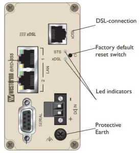
Connections
Ethernet TX Connections (RJ-45 connector) LAN1-2
| Position | Direction | Description |
| 1 | In/Out | TD+ |
| 2 | In/Out | TD- |
| 3 | In/Out | RD+ |
| 4 | – | Not Connected |
| 5 | – | Not Connected |
| 6 | In/Out | RD- |
| 7 | – | Not Connected |
| 8 | – | Not Connected |
Router Serial Port (DCE Female)
| Position | Name | Direction | Description |
1 | DCD | Out | Data Carrier Detect |
2 | RxD | Out | Receive Data |
3 | TxD | In | Transmit Data |
| 4 | DTR | In | Data Terminal Ready |
5 | SG | – | Signal Ground |
| 6 | DSR | Out | Data Set Ready |
7 | RTS | IN | Request to Send |
| 8 | CTS | Out | Clear to Send |
9 | RI | Out | Ring Indicator |
Power connector
| 2-position | Product marking | Direction | Description |
| No. 1 | – | Input | Common |
| No. 2 | + | Input | Supply voltage Input DC |
LED Indicators
LED | Status | Description |   |
STS Status | RED | Indicates a fault, except during boot-up | |
RED FLASH | Indicates a fault, except during boot-up | ||
GREEN | All OK | ||
GREEN & ONE RED FLASH | All OK but no VPN peer connected | ||
xDSL Link status | OFF | No ADSL connection | |
GREEN FLASH | Negotiating with the provider DSLAM | ||
GREEN | All OK, ADSL link established |
STS LED – Status indicator
The status indicator reports the health of the unit. In normal operation the indicator will be green, however, if a fault is detected, either at boot-up or during normal operation, the indicator will light red. When the unit is first switched on or is reset, the indicator will first light red then flash red. This is normal behavior during boot-up and does not indicate a fault.
Configuring a VPN connection in the BRD-355 and activating the service will cause the STS LED to be lit GREEN but FLASH RED every third (3) second to indicate that no peer is connected on the VPN. The feature of the VPN status in the STS LED makes it easy for staff to see whether or not the VPN connection is working without having to login to the device.
DSL LED – xDSL link status
The DSL LED reports the status of the connection to the network. When powered up the indicator will be off, the indicator will then flash green whilst the unit tries to negotiate the link with the provider DSLAM, once successfully connected to the provider the indicator will light green to indicate that everything is ready and functioning on the xDSL link level.
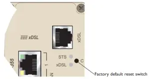
Factory Default Reset Switch
The reset switch is used to restore the configuration of the BRD-355 to the factory default settings (for details about the default settings see the Getting started section). The switch is accessed through a small hole, adjacent to the xDSL and STS LEDs, labeled C on the front of the unit.
To reset the configuration:
- Power down the unit.
- Using a suitable tool depress the reset switch.
- Power up the unit ensuring the switch remains depressed for approximately 5 seconds after power is applied. The STS LED will flash twice to indicate a reset.
- Once the unit has booted-up it will use the default settings.
Note: Using the factory default reset switch will erase all existing configuration settings and restore the factory default settings.
Protocols and Functionality
Ethernet Technologies | IEEE 802.3 for 10BaseT IEEE 802.3u for 100BaseTX Layer-2 QoS IEEE 802.1p Class of Service |
xDSL Technologies | RFC2684 Bridged LLC and Bridged VC-MUX ATM encap. (ADSL) TR-067 Compliance Dying Gasp support ITU K.21 Support Rate adaptive modem at 32 Kbps steps ATM Layer with traffic shaping QoS support (UBR, CBR, VBR-rt,VBR-nrt) AAL5 – AAL F5 OAM Loopback/Send and receive RFC2364 PPPoA client support RFC2516 PPPoE client support RFC2225 / RFC1577 Classical IP Support PAP/CHAP/MS-CHAP for Password Authentication support |
Serial Port Technologies | RS-232 Serial Over IP (Serial Extender and Virtual Serial Port) Modem emulation AT command interpreter MODBUS DNP3 |
IP Routing, Firewall, VPN and Cyber Security | Static IP routing Dynamic IP routing
VRRP |
Manageability | Management tools
|
For more information on the features and functionality, please refer to the Management Guide on the product website.
Getting started
Power Supply
The BRD-355 requires a DC power source in the voltage range of 10 to 60 VDC. The unit is designed to self protect from permanent damage if the voltage exceeds 60 VDC or if reverse polarity is applied. The router may need to be returned for service if this occurs. The router can also be damaged if there is any potential difference between the chassis-ground, RS-232 signal ground or power (–) input. Before connecting any wiring, ensure all components are earthed to a common ground point. An external isolator will be required if a positive earth power supply is used.
Ethernet
The Ethernet ports are on the front of the unit and are marked LAN 1 and LAN 2, each port has a LED indicating the connection speed and a LED indicating activity as shown in figure below. Both ports are capable of auto-negotiation, meaning cross-over cables are not required. The Ethernet ports are switched, allowing more than one Ethernet device to be connected to the unit at one time.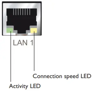
Configuration
Accessing and Using the Web Interface
All configuration of the BRD can be done via the web interface. In order to view the web pages a computer with a fixed IP address, on the same sub-net as the BRD, will need to be connected to one of the LAN ports.
The default IP settings of the BRD are:
- IP Address: 192.168.2.200
- Netmask: 255.255.255.0
The recommended IP settings for the PC used to configure the BRD Router:
- IP Address: 192.168.2.100
- Netmask: 255.255.255.0
- Default Gateway: 192.168.2.200
- Primary DNS: 192.168.2.200
Note: Although it is possible to connect the BRD directly to a Local Area Network (LAN) it is recommend that the network configuration as described in this section is performed prior to doing so. The DHCP server of the unit is by default disabled.
Accessing the BRD
- Open a web browser on the PC and browse to http://192.168.2.200 (the default MRD, IP address) .
- A login box will popup. If the box fails to display, re-check the cable connections to the unit and the IP address settings of the PC.
Enter the following login details:
- User Name: admin
- Password: westermo
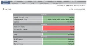
- The Status summary page will be displayed, it will be similar to Figure3.

Note: If the unit is not yet configured it is likely that the Network Status and Connection Status will indicate a fault condition. This is normal.
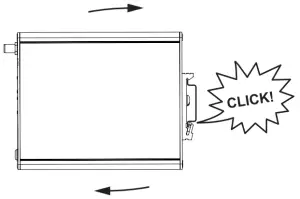
Mounting
This unit should be mounted on 35 mm DIN-rail, which is horizontally mounted inside an apparatus cabinet or similar. Snap on mounting, see figure.
Mounting the BRD-355 with integrated DIN-clip: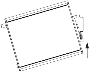
Cooling
This product uses convection cooling.
To avoid obstructing the airflow around the product, use the following spacing rules. Minimum spacing 25 mm (1.0 inch) above / below and 10 mm (0.4 inches) left / right the product. Spacing is recommended for the use of product in full operating temperature range and service life.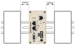
Dimensional drawing
Measurements are stated in millimeters.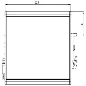
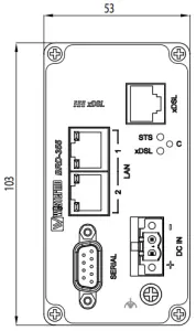
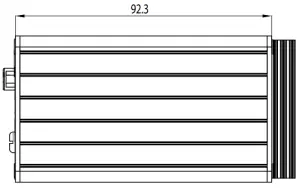
![]()
Westermo • SE-635 35 Stora Sundby, Sweden
Tel +46 16 42 80 00 Fax +46 16 42 80 01
E-mail: [email protected]
www.westermo.com


