
![]()

MRD-415 and MRD-455
Industrial Cellular Router
General Information
Legal Information
The contents of this document are provided “as is”. Except as required by applicable law, no warranties of any kind are made in relation to the accuracy and reliability or contents of this document, either expressed or implied, including but not limited to the implied warranties of merchantability and fitness for a particular purpose. Westermo reserves the right to revise this document or withdraw it at any time without prior notice.
Under no circumstances shall Westermo be responsible for any loss of data or income or any special, incidental, consequential, or indirect damages howsoever caused.
More information about Westermo can be found at www.westermo.com.
About This Guide
This guide is intended for installation engineers and users of the Westermo products.
It includes information on safety and regulations, a product description, installation instructions, and technical specifications.
Software Tools
Related software tools are available at www.westermo.com/support/software-tools.
License and Copyright for Included FLOSS
This product includes software developed by third parties, including Free/Libre Open Source Software (FLOSS). The specific license terms and copyright associated with the software are included in each software package respectively. Please visit the product web
a page for more information.
Upon request, the applicable source code will be provided. A nominal fee may be charged to cover shipping and media. Please direct any source code request to your normal sales or support channel.
Management Guide
This product runs MRX Operation System. Instructions for quick start, configuration, and factory reset are found in the Management Guide at www.westermo.com/support/productsupport/.
Safety and Regulations
Warning Levels
Warning signs are provided to prevent personal injuries and/or damages to the product.
The following levels are used:
| Level of warning | Description | Consequence personal injury | Consequence material damage |
| Indicates a potentially hazardous situation | Possible death or major injury | Major damage to the product |
| Indicates a potentially hazardous situation | Minor or moderate injury | Moderate damage to the product |
| Provides information in order to avoid misuse of the product, confusion, or misunderstanding | No personal injury | Minor damage to the product |
| Used for highlighting general, but important information | No personal injury | Minor damage to the product |
 WARNING
 CAUTION
 NOTICE
 NOTE
NOTETable 1. Warning levels
Safety Information
Before installation:
Read this manual completely and gather all information available on the product. Make sure it is fully understood. Check that your application does not exceed the safe operating specifications for the product.
SAFETY DURING INSTALLATION
The product must be installed and operated by qualified service personnel and installed into an apparatus cabinet or similar, where access is restricted to service personnel only.
During installation, ensure a protective earthing conductor is first connected to the protective earthing terminal (only valid for metallic housings). Westermo recommends a cross-sectional area of at least 4 mm2.
Upon removal of the product, ensure that the protective earthing conductor is disconnected last.
![]() HAZARDOUS VOLTAGE
HAZARDOUS VOLTAGE
Do not open an energized product. Hazardous voltage may occur when connected to a power supply.![]() PROTECTIVE FUSE
PROTECTIVE FUSE
The power supply wiring must be sufficiently fused.
It must be possible to disconnect manually from the power supply. Ensure compliance with national installation regulations.
![]() RADIO PRODUCTS
RADIO PRODUCTS
Observe the usage limitations of radio products at filling stations, in chemical plants, and in systems with explosives or potentially explosive locations.
The product may not be used in airplanes. Exercise particular caution near personal medical aids, such as pacemakers and hearing aids. Never perform work on the antenna system during a thunderstorm.
To fulfill human safety, a minimum separation distance of 20 cm or more should be maintained between the antenna of the product and personnel during operation.
![]() ELECTROSTATIC DISCHARGE (ESD)
ELECTROSTATIC DISCHARGE (ESD)
Prevent electrostatic discharge damage to internal electronic parts by discharging your body to a grounding point (e.g. use a wrist strap).
Care Recommendations
Follow the care recommendations below to maintain the full operation of the product and to fulfill the warranty obligations:
- Do not drop, knock or shake the product. Rough handling above the specification may cause damage to internal circuit boards.
- Use a dry or slightly water-damp cloth to clean the product. Do not use harsh chemicals, cleaning solvents, or strong detergents.
- Do not paint the product. Paint can clog the product and prevent proper operation.
If the product is used in a manner not according to specification, the protection provided by the equipment may be impaired.
If the product is not working properly, contact the place of purchase, the nearest Westermo distributor office, or Westermo technical support.
Product Disposal
This symbol means that the product shall not be treated as unsorted municipal waste when disposed of it. It needs to be handed over to an applicable collection point for recycling electrical and electronic equipment.
By ensuring the product is disposed of correctly, you will help to reduce hazardous substances and prevent potential negative consequences to both the environment and human health, which could be caused by inappropriate disposal.
![]()
Figure 1. WEEE symbol for treatment of product disposal
Compliance Information
Agency Approvals and Standards Compliance
Simplified Declaration of Conformity
Hereby, Westermo declares that this product is in compliance with applicable EU directives and UK legislation. The full declaration of conformity and other detailed information is available at www.westermo.com/support/product-support.
![]()
![]()
Figure 2. The European Conformity and the UK Conformity Assessment markings
Product Description
Product Description
The MRD-415 and MRD-455 industrial cellular routers make full use of the 2G, 3G, and 4G cellular networks to cost-effectively inter-connect systems, sites, and operators. Creating a solid foundation for smart automated systems, where machines can communicate with machines and service technicians can remotely monitor and maintain their valuable assets in any system.
Devices connected to the Internet require countermeasures against cybersecurity threats. The MRD series offers protection of transmissions from malicious eavesdroppers via encrypted communication tunnels (VPN) and features a simple, yet powerful, packet inspection firewall. Configuration of the device is done with a simple and intuitive web interface, management is also available with a basic CLI, and SMS messages can be used for controlling the device and receiving status updates.
The products feature a built-in 2-port Ethernet switch for connecting to any Ethernet device. For legacy support, there is also a built-in serial port that offers a simple modem replacement solution with the benefit of not having to reprogram or change any other component.
Features such as connection maintenance and network to network roaming ensure very high availability and a connection that is always available. This is crucial in mission-critical installations, where even the shortest downtime can prove very costly.
The MRD-415 comes in a very slim and robust casing which is ideal for wall mounting in small spaces, taking up very little space in a cabinet or similar. Connections come out on each end of the product, with antenna connectors on one side and Ethernet and serial interfaces on the other. It features a very low power consumption, making it the ideal choice for battery or solar-powered applications. Low power consumption combined with a clever power-saving feature allows the unit to run for a long time without the battery.
The MRD-455 comes in a very compact and robust casing ideal for mounting on DIN rails. All connections and LEDs are located on the front, making it ideal for installation in industrial cabinets and applications. To further strengthen the already high availability, they feature dual-SIM card slots, allowing the user to remove carrier dependency and swapping operators automatically if the primary run into trouble. It also features galvanic isolation between all interfaces (power supply, Ethernet, serial), to protect the product against electrical surges and overvoltage, which is common in many industrial applications.
Available Models MRD
| Art. no. | Model |
| 3623-0515 | MRD-415 |
| 3623-0401 | MRD-455 |
Table 2. List of available models
Hardware Overview
Hardware Overview
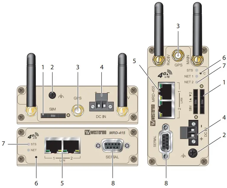
| No. | Description | ||
| 1 | SIM-card drawer(s) | 2 | Protective Earth |
| 3 | Antenna connectors (3 pcs) | 4 | Power connector |
| 5 | Ethernet TX ports | 6 | Factory reset switch |
| 7 | LED indicators | 8 | Serial port |
Table 3. Location of interface ports and LED indicators
Connector Information
DC Power Connection
| Illustration | Position | Product marking | Direction | Description |
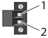 | 1 | – | Input | Common |
| 2 | + | Input | Supply voltage input DC |
Table 4. Power input
Ethernet
The Ethernet ports are on the front of the unit and are marked LAN 1 and LAN 2. Each port has a LED indicating the connection speed and a LED indicating activity. Both ports are capable of auto-negotiation, meaning cross-over cables are not required. The Ethernet ports are switched, allowing more than one Ethernet device to be connected to the unit at one time.
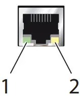
| No. | Description | No. | Description |
| 1 | Activity LED | 2 | Connection speed LED |
| Illustration | Pin no. | Signal | Direction | Description |
 | 1 | TD+ | In/Out | Transmitted/Received data |
| 2 | TD- | In/Out | Transmitted/Received data | |
| 3 | RD+ | In/Out | Transmitted/Received data | |
| 4 | – | – | Not connected | |
| 5 | – | – | Not connected | |
| 6 | RD- | In/Out | Transmitted/Received data | |
| 7 | – | – | Not connected | |
| 8 | – | – | Not connected |
Table 5. Ethernet TX connections (RJ-45 connector), LAN 1-2
Serial Port (DCE Female)
| Illustration | Position | Product marking | Direction | Description |
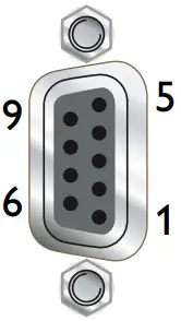 | 1 | DCD | Out | Data Carrier Detect |
| 2 | RxD | Out | Receive Data | |
| 3 | TxD | In | Transmit Data | |
| 4 | DTR | In | Data Terminal Ready | |
| 5 | SG | – | Signal Ground | |
| 6 | DSR | Out | Data Set Ready | |
| 7 | RTS | In | Request to Send | |
| 8 | CTS | Out | Clear to Send | |
| 9 | RJ | Out | Ring Indicator |
Table 6. Serial Port
LED Indicators
| LED | Status | Description |
| STS Status | RED | No wireless network has been detected |
| RED FLASH | A wireless network has been detected | |
| GREEN | Power up self-test OK/no issues | |
| NET NET 1 NET 2 Network indicator | OFF | Not ready |
| RED | RF circuitry initializing or network registration fault | |
| GREEN/RED | Network connection fault | |
| GREEN FLASH | Searching for network | |
| GREEN | Locked to network | |
| GREEN 1 BLINK | Signal strength indication: 1 – Very poor 2 – Normal 3 – Very good | |
| GREEN 2 BLINKS | ||
| GREEN 3 BLINKS | ||
| GREEN 4 BLINKS | ||
| GREEN 5 BLINKS | ||
| GREEN 6 BLINKS |
Table 7. LED indicators
Dimensions
Dimensions are stated in mm.
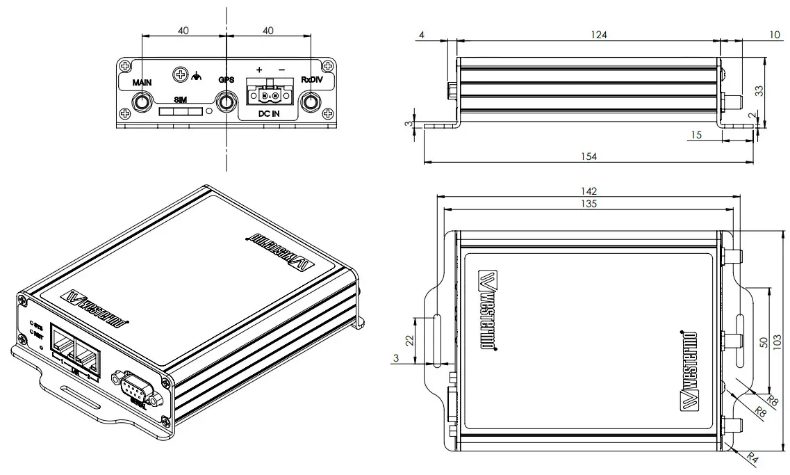
Figure 3. Dimensional drawing MRD-415
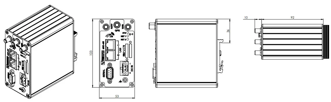
Figure 4. Dimensional drawing MRD-455
Installation
Mounting
This product should be mounted on a 35 mm DIN-rail, which is horizontally mounted inside an apparatus cabinet or similar. It is recommended that the DIN-rail is connected to the ground. Snap-on the product to the DIN rail according to the figure.
The MRD-415 includes an integrated mounting flange and can be attached to a panel or tray by means of screws, using the slots provided. Alternatively, it can be DIN rail mounted, using the DIN rail mounting kit.
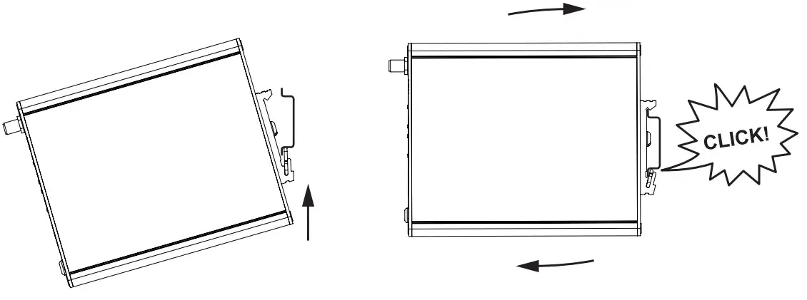
Figure 5. Mounting of product
Power Supply
The MRD requires a DC power source in the voltage range of 10 to 60 VDC. The product is designed to self-protect from permanent damage if the voltage exceeds 60 VDC or if the reverse polarity is applied. The product may need to be returned for service if this occurs.
The product can also be damaged if there is any potential difference between the chassis ground, RS-232 signal ground, power (–) input, or antenna shield. Before connecting any wiring, ensure all components are earthed to a common ground point. An external isolator will be required if a positive earth power supply is used.
Antennas
The units have three antenna connectors (SMA). Please ensure that the connecting nut is done up tightly in order to make a good connection.
Protective Earth Connection
For correct function, the earth connection needs to be properly connected to a designated PE rail. See the figure below.
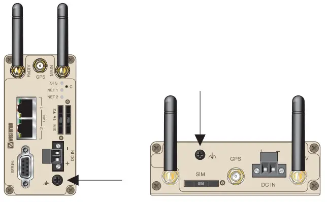
Figure 6. Earth connection
Cooling
This product uses convection cooling. Make sure that the unit is installed such as its ambient temperature is within its specified maximum/minimum temperature. Spacing is recommended for the use of the product in the full operating temperature range and service life. To avoid obstructing the airflow around the product, use the following spacing rules.
Minimum spacing of 25 mm (1 inch) above/below and 10 mm (0.4 inches) left/right of the product is recommended.
The product should be mounted in a clean and dry location, protected from water, excessive dust, corrosive fumes, extremes of temperature and direct sunlight. Allow sufficient ventilation to ensure adequate cooling of the product.
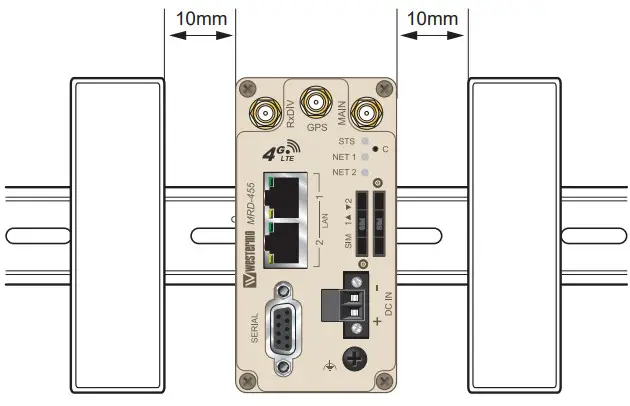
Figure 7. Minimum spacing of product
Installing the SIM Card
- To eject the SIM card drawer, press the SIM card eject button using a suitable tool and remove the drawer, refer to the figure for the location of the SIM card eject button.
- Insert the SIM card into the SIM card drawer with the contacts facing up, let chamfered corners align.
- Slide the drawer back into the unit ensuring that it locks into place.

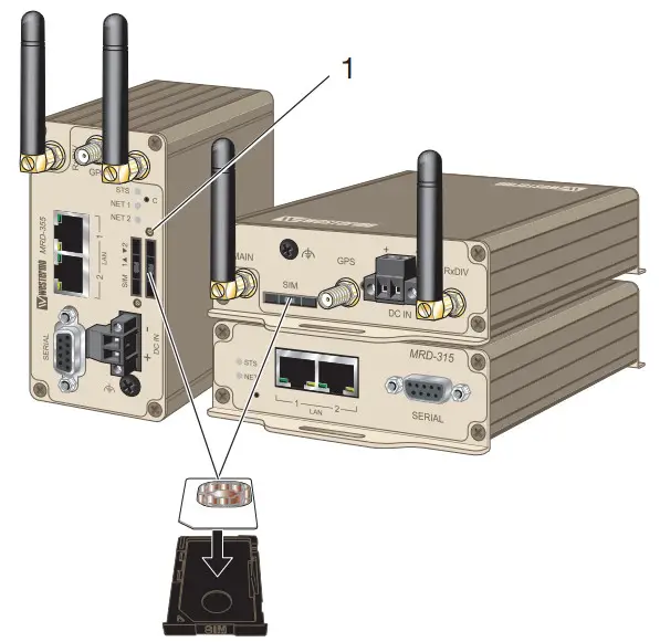
| No. | Description |
| 1 | SIM card drawer eject button |
![]() NOTE
NOTE
Before removing or inserting the SIM card, ensure that the power has been turned off and the power connector has been removed from the MRD.
Getting Started
All configuration of the product can be done via the web interface. In order to view the web pages, a computer with a fixed IP address, on the same subnet as the product, will need to be connected to one of the LAN ports.
The default IP settings of the product are:
IP Address: 192.168.2.200
Netmask: 255.255.255.0
Note: The DHCP server of the unit is by default disabled.
Accessing the MRD
- Open a web browser on the PC and browse to http://192.168.2.200 (the default MRD IP address).
- A login box will pop up. If the box fails to display, re-check the cable connections to the unit and the IP address settings of the PC.
- Enter the following login details:
Username: admin
Password: westermo
The Status summary page will be displayed.
Factory Default Reset Switch
The reset switch is used to restore the configuration of the MRD to factory default settings. The switch is accessed through a small hole on the rear of the unit adjacent to the power connector.
To reset the configuration:
- Power down the unit.
- Use a suitable tool and depress the reset switch.
- Power up the unit ensuring the switch remains depressed for approximately 10 seconds after power is applied. The STS LED and NET LED will flash twice to indicate a reset.
- The router will now re-boot as normal with the factory default settings.
![]() NOTE
NOTE
Using the Factory default reset switch will erase all existing configuration settings and restore the factory default settings. This includes the network connection profile settings APN, user name, and password.
Specifications
Protocols and Functionality
| DC, Power port | |
| Ethernet technologies | IEEE 802.3 for 10BaseT IEEE 802.3u for 100BaseTX |
| Serial port technologies | RS-232 Serial Over IP (Serial Extender and Virtual Serial Port) Router emulation AT command interpreter MODBUS DNP3 |
| Layer-2 QoS | IEEE 802.1p Class of Service |
| IP routing, firewall, VPN, and cybersecurity | Static IP routing Dynamic IP routing – RIPv1/v2 VRRP GRE Stateful inspection Firewall/ACL, NAT, Port Forwarding 25 x IPsec VPN, PSK and X.509a 1 x L2TP client 1 x PPTP client 1 x OpenVPN/SSL VPN client RADIUS PPP Dial-in/Dial out |
| Manageability | Management tools: web interface (HTTP and HTTPS), Command Line Interface (CLI) via SSHv2 and TELNET, SNMPv1/v2c/v3, SMS Control Flexible alarm/event handling system Syslog (log files and remote Syslog server) SNTP (NTP client) DHCP client DHCP server DDNS (Dynamic DNS update client) |
a25 x Configurable IPsec VPNs, processing power in relation to traffic over VPN sets limitations on the number of VPNs.
Interface Specifications
| DC, Power port | |
| Rated voltage | 24 – 48 VDC |
| Operating voltage | 19 – 60 VDC |
| Rated frequency | DC |
| Startup current | Maximum 400 mA |
| Polarity | Reverse polarity protected |
| Isolation | All other ports |
| Connector | Detachable screw terminal |
| Shielded cable | Not required |
aOnly applicable for MRD-455
| Ethernet TX | |
| Electrical specification | IEEE std 802.3 |
| Data rate | 10 Mbit/s, 100 Mbit/s, auto |
| Duplex | Full or half, auto |
| Circuit type | SELV |
| Transmission range | 100 m/328 ft |
| Isolation | All other ports |
| Connection | RJ-45, auto MDI/MDI-X |
| Cabling | Shielded cable is not required, except when installed in railway applications as signaling and telecommunications apparatus and located close to railsa |
| Conductive chassis | Yes |
| Number of ports | 2 |
aOnly applicable for MRD-455
| RS-232 | |
| Electrical specification | EIA RS-232 |
| Data rate | 300 bit/s – 115.2 kbit/s |
| Data format | 7 or 8 data bits, odd, even or none parity, 1 or 2 stop bits |
| Protocol | Transparent, optimized by packing algorithm |
| Circuit type | SELV |
| Transmission range | 15 m/49 ft |
| Connection | 9 pin D-sub female |
| Shielded cable | Not required |
| Conductive chassis | Yes |
| Number of ports | 1 |
| Cellular interface | MRD-415 frequency bands (MHz) | MRD-455 frequency bands (MHz) |
| 2G | GSM 900, DCS 1800 | GSM 900, DCS 1800 |
| 3G | B1, B3, B8 | B1, B5, B8 |
| 4G | B2, B3, B7, B8, B20, B28A | B1, B3, B5, B7, B8, B20, B38, B40, B41 |
| Category | LTE Cat. 1 | LTE Cat. 4 |
Type Tests and Environmental Conditions
| Environmental phenomena | Basic standard | Description | Test levels |
| ESD | EN 61000-4-2 | Enclosure | Contact: ±6 kV Air: ±8 kV |
| RF field AM modulated | IEC 61000-4-3 | Enclosure | 10 V/m (80-2700 MHz) |
| Fast transients | EN 61000-4-4 | Signal ports | MRD-415: ± 1 kV MRD-455: ± 2 kV |
| Power ports | ± 2 kV | ||
| Surge | EN 61000-4-5 | Signal ports | MRD-415: ± 1 kV (Crit. B) MRD-455: ± 2 kV |
| Power ports | MRD-415: ± 0.5 kV (Crit. B) MRD-455: ± 2 kV | ||
| Conducted RF immunity | EN 61000-4-6 | All ports | 10 V (0.15-80 MHz) |
| Conducted magnetic fields | EN 61000-4-8 | Only MRD-455 | 10 A/m |
| DC voltage dips | EN 61000-4-29 | 12 VDC and 24 VDC up to 300 ms (A), 1s (B) | |
| Radiated RF emission | CISPR 16-2-3 ANSI C63,4 (FCC part 15) | Enclosure | Class B |
| Conducted RF emission | CISPR 16-2-1 ANSI C63,4 (FCC part 15 b) | Signal ports | Class B |
| Power ports |
Table 8. EMC and electrical conditions
| Environmental phenomena | Basic standard | Description | Test levels |
| Temperatures | EN 60068-2-1 EN 60068-2-2 | Operational | -40 to +70°C |
| Storage and transport | -40 to +85°C | ||
| Humidity | EN 60068-2-30 | Operational | 0-95% relative humidity |
| Storage and transport | |||
| Altitude | Operational | 2000 m/70 kPa | |
| Service life | Operational | 10 years | |
| MTBF | MIL-217F | MRD-415: 1 367,000 hours MRD-455: 911,000 hours | |
| Vibration | IEC 61373 | ||
| Enclosure | Aluminum | ||
| Weight | MRD-415: 0.3 kg MRD-455: 0.4 kg | ||
| Degree of protection | EN 60529 | Enclosure | IP40 |
| Cooling | Convection |
Table 9. Environmental and mechanical conditions
Revision Notes
| Revision | Date | Change description |
| Rev. H | 2021-11 | Westermo logo updated, products MRD-315 and MRD-355 deleted from the user guide, new information structure throughout the manual. Agency approval and standards compliance EN/IEC 60950-1 deleted. |
![]()
Westermo • Metallverksgatan 6, SE-721 30 Västerås, Sweden
Tel +46 16 42 80 00 Fax +46 16 42 80 01
E-mail: [email protected]
www.westermo.com


