![]()
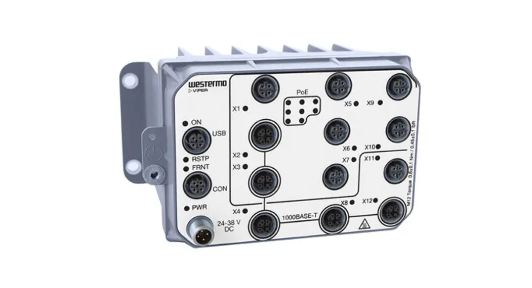
Viper-8 Series
EN 50155 Managed Gigabit Routing Switch
![]()
General Information
Legal Information
The contents of this document are provided “as is”. Except as required by applicable law, no warranties of any kind are made in relation to the accuracy and reliability or contents of this document, either expressed or implied, including but not limited to the implied warranties of merchantability and fitness for a particular purpose. Westermo reserves the right to revise this document or withdraw it at any time without prior notice.
Under no circumstances shall Westermo be responsible for any loss of data or income or any special, incidental, consequential, or indirect damages howsoever caused.
More information about Westermo can be found at www.westermo.com.
About This Guide
This guide is intended for installation engineers and users of the Westermo products.
It includes information on safety and regulations, a product description, installation instructions, and technical specifications.
Software Tools
Related software tools are available at www.westermo.com/support/software-tools.
License and Copyright for Included FLOSS
This product includes software developed by third parties, including Free/Libre Open Source Software (FLOSS). The specific license terms and copyright associated with the software are included in each software package respectively. Please visit the product web page for more information.
Upon request, the applicable source code will be provided. A nominal fee may be charged to cover shipping and media. Please direct any source code request to your normal sales or support channel.
WeOS
This product runs WeOS 5 (Westermo Operating System). Instructions for quick start, configuration, and factory reset are found in the WeOS user documentation at www.westermo.com.
Safety and Regulations
Warning Levels
Warning signs are provided to prevent personal injuries and/or damages to the product.
The following levels are used:
| Level of warning | Description | Consequence personal injury | Consequence material damage |
| Indicates a potentially hazardous situation | Possible death or major injury | Major damage to the product |
| Indicates a potentially hazardous situation | Minor or moderate injury | Moderate damage to the product |
| Provides information in order to avoid misuse of the product, confusion, or misunderstanding | No personal injury | Minor damage to the product |
| Used for highlighting general, but important information | No personal injury | Minor damage to the product |
 WARNING
 CAUTION
 NOTICE
 NOTE
NOTETable 1. Warning levels
Safety Information
Before installation:
Read this manual completely and gather all information available on the product. Make sure it is fully understood. Check that your application does not exceed the safe operating specifications for the product.
![]() SAFETY DURING INSTALLATION
SAFETY DURING INSTALLATION
The product must be installed and operated by qualified service personnel and installed into an apparatus cabinet or similar, where access is restricted to service personnel only.
Refer to chapter Compliance Information to see the required level of qualified service personnel according to safety standards.
During installation, ensure a protective earthing conductor is first connected to the protective earthing terminal (only valid for metallic housings). Westermo recommends a cross-sectional area of at least 4 mm2.
Upon removal of the product, ensure that the protective earthing conductor is disconnected last.
![]() HAZARDOUS VOLTAGE
HAZARDOUS VOLTAGE
Do not open an energized product. Hazardous voltage may occur when connected to a power supply.
![]() PROTECTIVE FUSE
PROTECTIVE FUSE
The power supply wiring must be sufficiently fused. The fuse must be IEC 60127 certified and rated for T1.6 A and 250 V.
It must be possible to disconnect manually from the power supply. Ensure compliance with national installation regulations.
This product has no internal fuse and should be connected via an external fuse for protection.
![]() REDUCE THE RISK OF FIRE
REDUCE THE RISK OF FIRE
To reduce the risk of fire, use only telecommunication line cords with a cable diameter of AWG 26 or larger. Regarding power cable dimensions, see chapter Interface Specifications.
![]() CABLE TEMPERATURE RATING FOR FIELD TERMINAL WIRES
CABLE TEMPERATURE RATING FOR FIELD TERMINAL WIRES
There may be a requirement on the minimum temperature rating of the cable to be connected to the field wiring terminals, see chapter Interface Specifications.
![]() ELECTROSTATIC DISCHARGE (ESD)
ELECTROSTATIC DISCHARGE (ESD)
Prevent electrostatic discharge damage to internal electronic parts by discharging your body to a grounding point (e.g. use a wrist strap).
![]() HOT SURFACE
HOT SURFACE
Be aware that the surface of this product may become hot. When it is operated at high temperatures, the external surface may exceed the Touch Temperature Limit according to the product’s relevant electrical safety standard.
![]() NOTE – MECHANICAL FORCE ON VENTILATION MEMBRANE
NOTE – MECHANICAL FORCE ON VENTILATION MEMBRANE
Do not cover or bring mechanical force to the ventilation membrane on the back of the product.
Care Recommendations
Follow the care recommendations below to maintain the full operation of the product and to fulfill the warranty obligations:
- Do not drop, knock or shake the product. Rough handling above the specification may cause damage to internal circuit boards.
- Use a dry or slightly water-damp cloth to clean the product. Do not use harsh chemicals, cleaning solvents, or strong detergents.
- Do not paint the product. Paint can clog the product and prevent proper operation.
If the product is used in a manner not according to specification, the protection provided by the equipment may be impaired.
If the product is not working properly, contact the place of purchase, the nearest Westermo distributor office, or Westermo technical support.
Product Disposal
This symbol means that the product shall not be treated as unsorted municipal waste when disposed of it. It needs to be handed over to an applicable collection point for recycling electrical and electronic equipment.
By ensuring the product is disposed of correctly, you will help to reduce hazardous substances and prevent potential negative consequences to both the environment and human health, which could be caused by inappropriate disposal.
![]()
Figure 1. WEEE symbol for treatment of product disposal
Compliance Information
2.5.1. Agency Approvals and Standards Compliance
| Type | Approval/Compliance |
| Climate | • EN 50155 class OT4 / IEC 60571 class TX, Railway applications – Electronic equipment used on rolling stock • IEEE 1478 class 1, condition E4 (incl Salt Mist), Environmental conditions for transit rail car electronic equipment |
| EMC | • EN/IEC 61000-6-2, Immunity industrial environments • EN/IEC 61000-6-4, Emission industrial environments • EN 50121-4/IEC 62236-4, Railway signaling and telecommunications apparatus • EN 50121-3-2/IEC 62236-3-2 Railway applications – Rolling stock – apparatus • Tested and verified for Class S1, DB EMC Regulation 06, Commodity team Radio compatibility in VDB Rev 1.0 (Shunting Radio) • Tested and verified for FCC part 15b class A (CFR 47) |
| Mechanical (Shock and vibration) | • EN 61373 category 1, class A and B • IEEE 1478 class 1, condition E4, including shock tests of 10 g/30 ms and 20 g/11 ms in all directions |
| Insulation (Coordination and test) | • EN 50124-1, Railway applications – Insulation coordination • EN 50155/IEC 60571, Railway applications – Electronic equipment used on rolling stock |
| Fire protection | • EN 45545-2, Fire protection on railway vehicles • NFPA 130, Fire protection for fixed guideway transit and passenger rail system |
| Software | • EN 50657:2017 Software Onboard Rolling Stock (Basic Integrity) |
| Safety | • EN/IEC/UL 61010-1, -2-201, Safety requirements for electrical equipment for measurement, control, and laboratory use |
2.5.2. EN/IEC/UL 61010-2-201 Notice
This product has been tested and found compliant with EN/IEC/UL 61010-2-201, Safety requirements for electrical equipment for measurement, control, and laboratory use. In accordance with the definitions of the standard, this product shall be handled by skilled service personnel.
2.5.3. FCC Part 15.105 Class A Notice
This product has been tested and found to comply with the limits for a Class A digital device, pursuant to Part 15 of the FCC Rules.
These limits are designed to provide reasonable protection against harmful interference when the product is operated in a commercial environment.
This product generates, uses, and can radiate radio frequency energy and, if not installed and used in accordance with the user manual, may cause harmful interference to radio communications. Operation of this product in a residential area is likely to cause harmful interference in which case the user will be required to correct the interference at the user’s own expense.
2.5.4. Simplified Declaration of Conformity
Hereby, Westermo declares that this product is in compliance with applicable EU directives and UK legislation. The full declaration of conformity and other detailed information is available at www.westermo.com/support/product-support.
![]()
![]()
Figure 2. The European Conformity and the UK Conformity Assessment markings
Product Description
Product Description The Viper-8 series is a managed backbone routing switch optimized for the needs of the railway rolling stock market. Gbps ports cope with high bandwidth backbone, consist ring, and end devices.
The product is designed to withstand the tough environment on-board trains, exposing the switch to constant vibration, extreme temperatures, humidity, and a demanding electrical environment.
A GORE-TEX® membrane prevents internal condensation. Threading integrated into the chassis provides for additional vibration resistance. High-level isolation between all interfaces enables direct connectivity to vehicle auxiliary power and protects against overvoltage and flashover. IP67 protection prevents the ingress of water and dust. An overall optimized design results in an extremely compact package in combination with very high MTBF for easy integration and low lifecycle cost.
Thorough type testing at independent ISO/IEC 17025 and ILAC MRA certified labs, accredited to a wide range of standards, show that the Viper series fulfills EN 50155 and other requirements. The state-of-the-art Westermo production facility ensures the quality of each individual unit, e.g. through temperature cycling burn-in testing.
The WeOS operating system offers an extensive suite of IP networking features for resilient and flexible networks, e.g. the FRNT ring protocol with very fast failover. The powerful layer 3 routing capability ensures communication between the backbone and consist networks and offers full support for IEC 61375, including TTDP network inauguration and TRDP real-time data protocol. The backup device accessory matches the Viper in robustness and offers easy configuration update and backup.
Available Models
| Art. no. | Model | Software | Gbps ports |
| 3635-2210 | Viper-108-T8G | L2 | 8 |
| 3635-2220 | Viper-208-T8G | L3 | 8 |
Table 2. Available Viper 8 models
![]() NOTE – MECHANICAL FORCE ON VENTILATION MEMBRANE
NOTE – MECHANICAL FORCE ON VENTILATION MEMBRANE
Do not cover or bring mechanical force to the ventilation membrane on the back of the product.
Hardware Overview
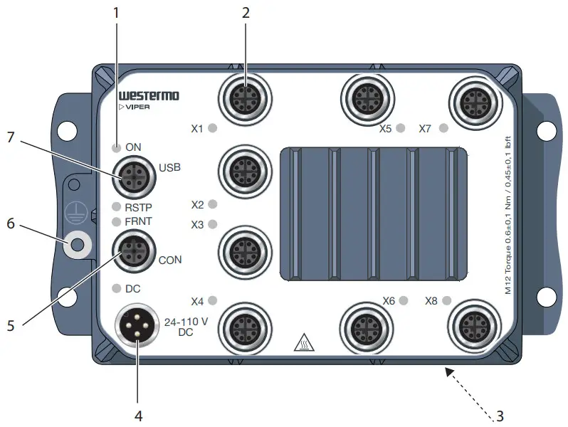
Figure 3. Location of interface ports and LED indicators
| No. | Description | No. | Description |
| 1 | LED indicator | 2 | Gbps port (8 pcs) |
| 3 | GORE-TEX ventilation membrane on the rear side | 4 | Power connection |
| 5 | Console port | 6 | Protective earth connection |
| 7 | USB port |
Connector Pinout
| Pin no. | Signal | Illustration |
| 1 | +DC1 | 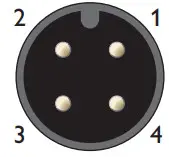 |
| 2 | +DC2 | |
| 3 | -COM | |
| 4 | -COM | |
| Viper supports redundant power connections. The positive inputs are +DC1 and +DC2. The negative input for both supplies is -COM | ||
Table 3. Power connector, A-coded
| Pin no. | Signal | Illustration |
| 1 | NCa | 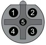 |
| 2 | TX | |
| 3 | RX | |
| 4 | NCa | |
| 5 | GND |
*No Connect. Do not connect.
Table 4. Console connector, B-coded
| Pin no. | Signal | Illustration |
| 1 | DN | 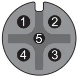 |
| 2 | VBUS | |
| 3 | NCa | |
| 4 | DC | |
| 5 | GND |
*No Connect. Do not connect.
Table 5. USB connector, A-coded
| Pin no. | Signal | Illustration |
| 1 | DA+ |  |
| 2 | DA- | |
| 3 | DB+ | |
| 4 | DB- | |
| 5 | DD+ | |
| 6 | DD- | |
| 7 | DC- | |
| 8 | DC+ |
Table 6. Gbps connector, X-coded
LED Indicators
| LED | Status | Description |
| ON | OFF | The product has no power |
| GREEN | All OK, no alarm condition | |
| RED | Alarm condition, or until the product has started up. (Alarm conditions are configurable, see WeOS Management Guide) | |
| RSTP | OFF | RSTP disabled |
| GREEN | RSTP enabled | |
| BLINK | The product selected as RSTP/STP root switch | |
| FRNT | OFF | FRNT disabled |
| GREEN | FRNT OK | |
| RED | FRNT error | |
| BLINK | Product configured as FRNT focal point | |
| DC | OFF | The product has no power |
| GREEN | Power OK on DC1 and DC2 | |
| RED | Power failure on DC1 or DC2 | |
| X1 to X8 | OFF | No link |
| GREEN | Link established | |
| GREEN FLASH | Data traffic indication | |
| YELLOW | Port alarm or port is set in blocking state by link redundancy protocol |
Table 7. LED indicators
Dimensions
Dimensions are stated in mm and apply to both models.
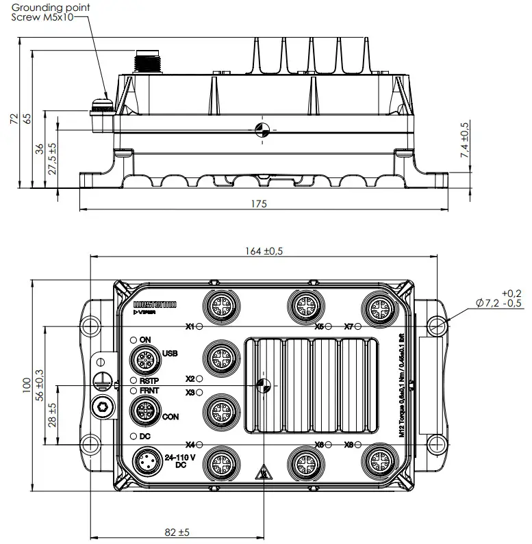
Figure 4. Dimensional drawing
Installation
Wall Mounting
The product can be wall-mounted vertically or horizontally. There are four pieces of 7 mm bores for this. Use four M5, M6 or 1/4″ screws with 12 mm washers on a flat and stable surface.
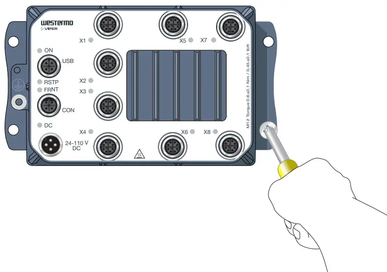
Figure 5. Wall mounting
Protective Earth Connection
For correct function, the earth connection needs to be properly connected to a designated PE rail. See the figure below. Torque: 3.2 Nm.
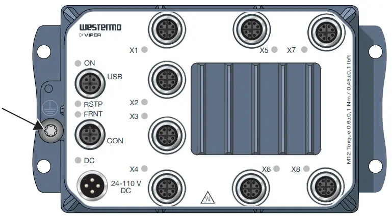
Figure 6. Earth connection
Connection of Cables
Recommended tightening torque for the M12 connectors is 0.6 Nm. All M12 connections are screw connections.
When connecting the power cable, ensure that the pins are connected correctly before tightening the power cable to the unit.
![]() PROTECTIVE FUSE
PROTECTIVE FUSE
The power supply wiring must be sufficiently fused. The fuse must be IEC 60127 certified and rated for T1.6 A and 250 V.
It must be possible to disconnect manually from the power supply. Ensure compliance with national installation regulations.
This product has no internal fuse and should be connected via an external fuse for protection.
![]() NOTE – UNUSED CONNECTORS
NOTE – UNUSED CONNECTORS
Unused connectors must be covered by a protective cap (delivered with the product), and tightened to the specified torque in order to fulfill the specified ingress protection code.
Cooling
This product relies on convection cooling. Make sure that it is installed so that the ambient temperature is within the specified temperature range. Avoid obstruction of the airflow around the product.
Replacement of Product
Disconnect all cables and unscrew the product from the wall. Mount the replacement product and reconnect all cables, observing the instructions in Connection of Cables [15]. For easy replication of the configuration of the original product, it is recommended to have the Westermo USB plug permanently connected to the USB port and move it over to the replacement product before it is powered up.
MTTR (Mean Time To Repair), i.e. time for replacement of the product is: < 8 minutes.
![]() HOT SURFACE
HOT SURFACE
Be aware that the surface of this product may become hot. When it is operated at high temperatures, the external surface may exceed Touch Temperature Limit according to the product’s relevant electrical safety standard.
EN 45545-2 Mounting Notes
Two products can be mounted together and as a single interior non-listed group in the sense of EN 45545-2 definitions. For multiple products, the spacing requirements for interior non-listed groups must be met.
Specifications
Interface Specifications
| DC, Power port | |
| Rated voltagea | 24 to 110 VDC |
| Operating voltageb | 16.8 to 143 VDC (14.4 VDC for 100 ms and 154 VDC for 1 s) |
| Rated current | Max 460 mA at 24 VDC, max 110 mA at 110 VDC |
| Rated frequency | DC |
| Inrush current | 80 mA²s at 24 VDC, 140 mA²s at 110 VDC |
| Startup current | Max 560 mA at 16.8 VDC |
| Polarity | Reverse polarity protected |
| Redundant power input | Yes |
| Isolation | To all other ports |
| Connector | 4-pin, male, M12 screw connection, A-coded, recommended Westermo cables: 3146-1106 for 1.5 m3146-1107 for 5 m |
| Cable size | M12, recommended power cable area 0.5 mm² (minimum 0.25 mm²), which correlates to AWG 21 or larger Cable dimensions depend on the choice of M12 connector |
| Cable temperature rating | For minimum temperature rating of the cable to be connected to the field wiring terminals: -40 to +70 °C |
| Circuit type | Secondary circuit hazardous voltage, OVC II |
aAlso referred to as nominal voltage in EN/IEC 61010-1
bAlso referred to as nominal input including fluctuations in EN/IEC 61010-1
| Gbps ports | |
| Electrical specification | IEEE std 802.3 |
| Data rate | 10 Mbps, 100 Mbps, 1 Gbps, manual or auto |
| Duplex | Full or half, manual or autoa |
| Transmission range | Up to 150 m with CAT5e cable or better |
| Isolation | To all other ports |
| Connector | 8-pin, female, M12 screw connection, X-coded |
| Cabling | Shielded cable CAT5e or better is recommended |
| Conductive chassis | Yes |
| FRNT reconfiguration time | Typically below 20 ms |
| Circuit type | TNV-1 |
aFor 1 Gbps, auto-negotiation is always enabled
| USB port | |
| Electrical specification | USB 2.0 host interface |
| Data rate | Up to 480 Mbps (high-speed mode) |
| Maximum supply current | 500 mA |
| Isolation | To all Ethernet and DC ports No isolation to CON or protective earth |
| Connector | 5-pin, female, M12 screw connection, A-coded, recommended Westermo USB plug 3641-0190 |
| Circuit type | SELV |
| Console port | |
| Electrical specification | RS-232 |
| Data rate | 115.2 kbit/s |
| Data format | 8 data bits, no parity, 1 stop bit, no flow control |
| Isolation | To all Ethernet and DC ports No isolation to USB or protective earth |
| Connector | 5-pin, female, M12 screw connection, B-coded, recommended Westermo cables: 1211-2215 (serial port) or 1211-4073 (USB) |
| Circuit type | SELV |
Type Tests and Environmental Conditions
Environmental phenomena | Basic standard | Description | Test levels |
| ESD | EN 61000-4-2 | Enclosure | Contact: ±6 kV Air: ±8 kV |
| Fast transients | EN 61000-4-4 | Power port | ± 2 kV |
| Signal ports | |||
| Earth port | |||
| Surge | EN 61000-4-5 | Power port | L-E: ± 2 kV, 42 Ω, 0.5 µF, 1.2/50 µs L-E: ± 0.5 kV, 12 Ω, 9 µF, 1.2/50 µs L-L: ± 2 kV, 42 Ω, 0.5 µF, 1.2/50 µs L-L: ± 0.5 kV, 2 Ω, 18 µF, 1.2/50 µs |
| Ethernet port | L-E: ± 2 kV, 2 Ω | ||
| Radiated RF immunity | EN 61000-4-3 | Enclosure | 20 V/m at (80 MHz to 2 GHz) 10 V/m at (2-6 GHz) 1 kHz sine, 80% AM |
| Conducted RF immunity | EN 61000-4-6 | Power port | 10 V, 80% AM, 1 kHz; (0.15-80) MHz |
| Ethernet ports | |||
| Earth port | |||
| Radiated RF emission | CISPR 16-2-3 | Enclosure | EN 61000-6-4 (30-6000 MHz) |
| ANSI C63,4 (FCC Part 15b) | Class A | ||
| Conducted RF emission | CISPR 16-2-1 | Power port | EN 61000-6-4 |
| CISPR 32 | Ethernet ports | EN 61000-6-3 | |
| Insulation resistance | EN 50155 | All ports | ≥20 MΩ at 500 VDC |
| Dielectric strength | EN 50155 | Power port to all other ports | 2250 VDC, 1 min |
| Ethernet ports to all other ports | 2250 VDC, 1 mina |
a750 VDC after damp heat, according to EN 50155
Table 8. EMC and electrical conditions
| Environmental phenomena | Basic standard | Description | Test levels |
| Temperatures | EN 60068-2-1 EN 60068-2-2 | Operational | -40 to +70°C (-40 to +158°F)ab |
| Storage and transport | -55 to +85°C (-67 to +185°F) | ||
| Humidity | EN 60068-2-30 | Operational | 5-95% relative humidity |
| Storage and transport | |||
| Altitude | Operational | 2000 m | |
| Service life | Operational | 20 years according to IEC/TR 62380 | |
| MTBF | 1: MIL- HDBK-217F- N2, GB, +25°C/ +77°F 2: IEC 62380 | 1: 659,000 hrs, 2: 603,000 hrs | |
| Vibration | IEC 60068-2-6 (sine) | Operational | 5 sweeps cycles: 7.5 mm 5-8 Hz 2g, 8-500 Hz |
| IEC 60068-2-64 (random) | Non-operational long life simulation | 11.44 m/s² rms 5-150 Hz, 5 hours 20 m/s² rms 5-150 Hz, 30 min operational | |
| Shock | IEC 60068-2-27 | Operational | 10 g, 30 ms, half-sine 20 g, 11 ms, saw tooth |
| Weight | 1.45 kg | ||
| Degree of protection | IEC 60529 | Enclosure | IP67, no ingress of dust, and protection against water immersion up to 1 m. Also passes IP66 tests.c |
| Cooling | Convection | ||
| Overvoltage category | EN/IEC/UL 61010-1 | OVC II | |
| Pollution degree | EN/IEC/UL 61010-1 | PD3 macro environment and PD2 microenvironment | |
| EN 50124-1 | PD2 | ||
| Location | EN/IEC/UL 61010-1 | Outdoor, wet locations | |
| IEEE 1478 | Class 1, condition E4. Indoor |
Refer to “Safety and Regulations” chapter regarding touch temperature
bOperational at +85°C for a limited time
cProvided all connectors are connected with IP66 and IP67 cablings or fitted with protective caps (delivered with the unit) and tightened to the specified torque.
dInstallation and maintenance shall be made in controlled environments.
Table 9. Environmental and mechanical conditions
Revision Notes
Revision | Date | Change description |
| Rev. E | 2022-03 | 3.4 Connector Pinout; Faulty footnote at Gbps connector removed. |
| Rev. D | 2022-01 | 2.2 Safety Information updated (Warning – Safety during installation), 2.5.2 EN/IEC/UL 61010-2-210 Notice added, 5.2 Type Tests and Environmental Conditions updated (UL added to EN/IEC 61010-1) |
| Rev. C | 2021-12 | 5.1 Interface Specification updated (DC Power port; operating voltage) |
| Rev. B | 2021-12 | E-mark removed from 2.5.1 Agency Approvals and Standards Compliance |
| Rev. A | 2021-10 | First version |
![]()
Westermo • Metallverksgatan 6, SE-721 30 Västerås, Sweden
Tel +46 16 42 80 00 Fax +46 16 42 80 01
E-mail: [email protected]
www.westermo.com


