
westermo Viper-012 Unmanaged EN 50155 Switch
General information
Legal information
The contents of this document are provided “as is”. Except as required by applicable law, no warranties of any kind are made in relation to the accuracy and reliability or contents of this document, either expressed or implied, including but not limited to the implied warranties of merchantability and fitness for a particular purpose. Westermo reserves the right to revise this document or withdraw it at any time without prior notice. Under no circumstances shall Westermo be responsible for any loss of data or income or any special, incidental, and consequential or indirect damages howsoever caused. More information about Westermo can be found at www.westermo.com
Safety and Regulations
Warning signs are provided to prevent personal injury and/or damages to the product. The following levels are used:
| Level of warning | Description | Consequence personal injury | Consequence material damage |
| WARNING | Indicates a potentially hazardous situation | Possible death or major injury | Major damage to the product |
| CAUTION | Indicates a potentially hazardous situation | Minor or moderate injury | Moderate damage to the product |
| NOTICE | Provides information in order to avoid misuse of the product, confusion or misunderstanding | No personal injury | Minor damage to the product |
| NOTE | Used for highlighting general, but important information | No personal injury | Minor damage to the product |
Before installation:
Read this manual completely and gather all information on the product. Make sure that you understand it fully. Check that your application does not exceed the safe operating specifications for this product.
SAFETY DURING INSTALLATION
The product must be installed by qualified service personnel and built in to an apparatus cabinet or similar, where access is restricted to service personnel only. During installation, ensure a protective earthing conductor is first connected to the protective earthing terminal (only valid for metallic housings). Westermo recommends a cross-sectional area of at least 4 mm2. Upon removal of the product, ensure that the protective earthing conductor is disconnected last.
PROTECTIVE FUSE
The power supply wiring must be sufficiently fused. It must be possible to disconnect manually from the power supply. Ensure compliance to national installation regulations. This product has no internal fuse and should be connected via an external fuse for protection.
REDUCE THE RISK OF FIRE
To reduce the risk of fire, use only telecommunication line cords with a cable diameter of AWG 26 or larger. Regarding power cable dimensions, see Interface Specifications.
HOT SURFACE
Be aware that the surface of this product may become hot. When it is operated at high temperatures, the external surface may exceed Touch Temperature Limit according to the product’s relevant electrical safety standard.
ELECTROSTATIC DISCHARGE (ESD)
Prevent electrostatic discharge damages to internal electronic parts by discharging your body to a grounding point (e.g. use a wrist strap).
Care recommendations
Follow the care recommendations below to maintain full operation of product and to fulfill the warranty obligations:
- Do not drop, knock or shake the product. Rough handling above the specification may cause damage to internal circuit boards.
- Use a dry or slightly water-damp cloth to clean the product. Do not use harsh chemicals, cleaning solvents or strong detergents.
- Do not paint the product. Paint can clog the product and prevent proper operation.
If the product is used in a manner not according to specification, the protection provided by the equipment may be impaired. If the product is not working properly, contact the place of purchase, nearest Westermo distributor office or Westermo technical support.
Product disposal
This symbol means that the product shall not be treated as unsorted municipal waste when disposing of it. It needs to be handed over to an applicable collection point for recycling electrical and electronic equipment. By ensuring this product is disposed of correctly, you will help to reduce hazardous substances and prevent potential negative consequences to both environment and human health, which could be caused by inappropriate disposal.
Declaration of Conformity
Hereby, Westermo declares that this product is in compliance with applicable EU directives and UK legislations. The full declaration of conformity and other detailed information is available at www.westermo.com/support/product-support.
Agency approvals and standards compliance
| Type | Approval / Compliance |
| EMC | EN 61000-6-1, Immunity residential environments |
| EN 61000-6-2, Immunity industrialokokvironments | |
| EN 61000-6-3, Emission residential environments | |
| EN 61000-6-4, Emission industrial environments | |
| EN 50121-3-2, Railway applications – Rolling stock – apparatus | |
| EN 50121-4/IEC 62236-4, Railway signaling and telecommunications apparatus | |
| Environmental | EN 61373, Railway applications – Rolling stock equipment. Shock and vibration tests |
| IEEE 1478, Environmental conditions for transit rail car electronic equipment | |
| EN 50124-1, Railway applications – Insulation coordination | |
| EN 50155, Railway applications – Electronic equipment used on rolling stock | |
| IEC 60068-2-27, (shock 100g, 6 ms, halfsine) | |
| EN 45545-2, Fire safety standard |
FCC Part 15.105 Notice:
This equipment has been tested and found to comply with the limits for a Class B digital device, pursuant to Part 15 of the FCC Rules. These limits are designed to provide reasonable protection against harmful interference in a residential installation. This equipment generates, uses and can radiate radio frequency energy and, if not installed and used in accordance with the instructions, may cause harmful inter-ference to radio communications. However, there is no guarantee that interference will not occur in a partic ular installation. If this equipment does cause harmful interference to radio or television reception, which can be determined by turning the equipment off and on, the user is encouraged to try to correct the interference by one or more of the following measures:
- Reorient or relocate the receiving antenna
- Increase the separation between the equipment and receiver
- Connect the equipment into an outlet on a circuit different from that to which the receiver is connected
- Consult the dealer or an experienced radio/TV technician for help.
Type tests and environmental conditions
| Environmental phenomena | Basic standard | Description | Test levels |
| ESD | EN 61000-4-2 | Enclosure | Contact: ±6 kV Air: ±8 kV |
| Fast transients | EN 61000-4-4 | Power port | ±5 kV |
| Signal ports | ±2 kV | ||
| Earth port | ±1 kV | ||
| Surge | EN 61000-4-5 | Power port | L-E: ±2 kV, 12Ω, 9 μF, 1.2/50 μs L-L: ±1 kV, 2Ω, 18 μF, 1.2/50 μs L-E: ±2 kV, 42Ω, 0.5 μF, 1.2/50 μs L-L: ±2 kV, 42Ω, 0.5 μF, 1.2/50 μs L-E: ±8.4 kV, 100Ω, 0.05/0.1 μs L-L: ±8.4 kV, 100Ω, 0.05/0.1 μs |
| Ethernet ports | L-E: ±2 kV, 2 Ω | ||
| Power frequency magnetic field | EN 61000-4-8 | Enclosure | 300 A/m; 0, 16.7, 50, 60 Hz |
| Pulsed magnetic field | EN 61000-4-9 | Enclosure | 300 A/m |
| Radiated RF immunity | EN 61000-4-3 | Enclosure | 20 V/m @ (80 MHz – 2.7 GHz) 1 kHz sine, 80% AM 10 V/m @ (2.7 – 6 GHz) 1 kHz sine, 80% AM |
| Conducted RF immunity | EN 61000-4-6 | Power port | 10 V, 80% AM, 1 kHz; (0.15 – 80) MHz |
| Ethernet ports | 10 V, 80% AM, 1 kHz; (0.15 – 80) MHz | ||
| Earth port | 10 V, 80% AM, 1 kHz; (0.15 – 80) MHz | ||
| Radiated RF emission | CISPR 16-2-3 | Enclosure | Class B (30 – 6000 GHz) |
| ANSI C63,4 (FCC Part 15) | Class B (30 – 6000 GHz) | ||
| Conducted RF emission | CISPR 16-2-1 | Power port | Class B |
| Ethernet ports | Class B | ||
| Dielectric strength | EN 60950-1 | Power port to all other ports | 1.5 kV ACrms, 50 Hz, 1 min |
| Fast Ethernet ports to all other ports | 1.5 kVACrms, 50 Hz, 1 min | ||
| Environmental | |||
| Temperatures | EN 60068-2-1 EN 60068-2-2 | Operating | –40 to +70°C (–40 to +158°F)* |
| Storage and transport | –50 to +85°C (–58 to +185°F) | ||
| Humidity | EN 60068-2-30 | Operating | 5 to 95% relative humidity |
| Storage and transport | 5 to 95% relative humidity | ||
| Altitude | Operating | 2 000 m / 70 kPa | |
| Service life | Operating | 15 years | |
| MTBF | 636,000 hours | MIL-C217F2, GB, 25°C (+77°F) | |
| Vibration | IEC 60068-2-6 (sine) | Non operating long life simulation | 7.9 m/s² (RMS) 5 – 150 Hz |
| IEC 60068-2-64 (random) | Operating | 1 m/s² (RMS) 5 – 150 Hz | |
| Shock | IEC 60068-2-27 | Operating | 10 g, 30 ms, 20 g, 11 ms, 100 g, 6 ms |
| Bump | IEC 60068-2-27 | Operating | 10 g, 11 ms |
| Enclosure | Zinc | Fire enclosure | |
| Dimension W x H x D With connectors | See “Dimensions” chapter for details | ||
| Weight | 1.4 kg | ||
| Degree of protection | EN 60529 | Enclosure | IP67** |
| Cooling | Convection | ||
Description
Designed for harsh industrial environments The Viper-012 is a unmanaged rugged Ethernet switch designed for applications with severe operating conditions and extreme environments.
With an ultra robust design, sealed to IP67 and vibration resistant to and exceeding on-board rail standards this unit is ideal for situations where mechanical stress, moisture, condensation, dirt or continuous vibrations could adversely affect the function of standard Ethernet switches. Fully approved for onboard rolling stock, this unit can be deployed in e.g. trains, trams, busses, mining trucks, army vehicles and drilling rigs.
Product model
3641-0540 Viper-012 unmanaged switch.
Interface specifications
| DC, Power port | |
| Rated voltage | 24 to 110 VDC |
| Operating voltage | 16.8 to 143 VDC (14.4 to 154 VDC for 100 ms) |
| Rated current | Viper-x12: Max 350 mA @ 24 V, max 90 mA @ 110 V Viper-x12-T3G: Max 550 mA @ 24 V, max 120 mA @ 110 V |
| Rated frequency | DC |
| Inrush current, I²t | 1 mA²s @ 24 V and 6 mA²s @ 110 V |
| Startup current* | 535 mA @ 24 V 145 mA @ 110 V |
| Polarity | Reverse polarity protected |
| Redundant power input | Yes |
| Isolation to | 1500 VAC rms to all other |
| Connection | 4 pin male M12 A-coded connector, use Westermo cable 3146-1106 for 1.5 m 3146-1107 for 5 m |
| Connector size | M12, recommended cable area 0.5 mm² recommended (minimum 0.25 mm²), cable dimensions depend on choice of M12 connector |
External supply current capability for proper start-up
| X1-X12 Ethernet ports | |
| Electrical specification | IEEE std 802.3. 2005 Edition |
| Data rate | 10 Mbit/s, 100 Mbit/s, manual or auto |
| Duplex | Full or half, manual or auto |
| Circuit type | Viper-x12: X1-X12: TNV-1 Viper-x12-T3G: X1-X3, X5-X7, X9-X11: TNV-1 X4, X8, X12: SELV |
| Transmission range | Up to 150 m with CAT5e cable or better |
| Isolation to | Viper-x12: 1500 VAC rms to all other ports Viper-x12-T3G: X1-X3, X5-X7, X9-X11: 1500 VAC rms to other ports X4, X8, X12: 500 VAC rms to other ports |
| Connection | 4-pin M12 D-code, auto MDI/MDI-X, use e g Westermo cable 3146-1100 M12-M12 – 1 m 3146-1101 M12-M12 – 5 m 3146-1103 RJ45-M12 – 1 m 3146-1104 RJ45-M12 – 5 m |
| Shielded cable | Not required, but recommended in severe electromagnetic environments |
| Conductive housing | Yes |
| Number of ports | 12 |
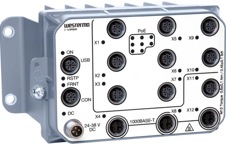
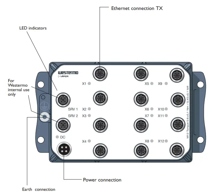
Location of interface ports and LED
Power Connector Pin-out
| Pin number | Signal | 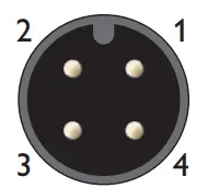
|
| No 1 | +DC1 | |
| No 2 | +DC2 | |
| No 3 | -COM | |
| No 4 | -COM |
LED Indicators
| LED | Status | Description |
| DC | OFF | Unit has no power. |
| GREEN | Power OK on DC1 and DC1. | |
| RED | Power failure on DC1 or DC2. | |
| X1 to X12 | OFF | No Link. |
| GREEN | Link established. | |
| GREEN FLASH | Data traffic indication. | |
| YELLOW | Port alarm and no link. |
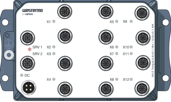
- SRV 1 & SRV 2 only for internal use by Westermo staff
Wall mounting
There are four 6 mm bore holes intended for mounting the unit. The unit can be mounted vertical or horizontal. Use four M5 screws with 12 mm washer on a flat and stable surface.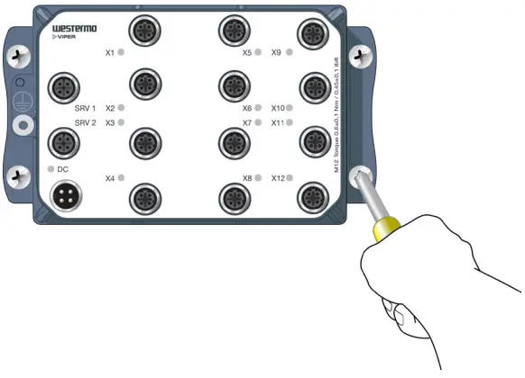
Connection of cables
Recommended tightening torque for the M12 connectors: 0.6 Nm
Note that unused connectors must be covered by a protective cap (delivered with the unit), tightened to the specified torque, in order to fulfill the specified ingress protection code.
Removal
Disconnect all cables and unscrew the unit from the wall.
Time For Replacement < 15 minutes
Cooling
This unit relies on convection cooling. Make sure that it is installed so that the ambient temperature is within the specified temperature range, e.g. by avoiding obstruction of the airflow around the unit.
Dimensions
Measurements are stated in millimeters.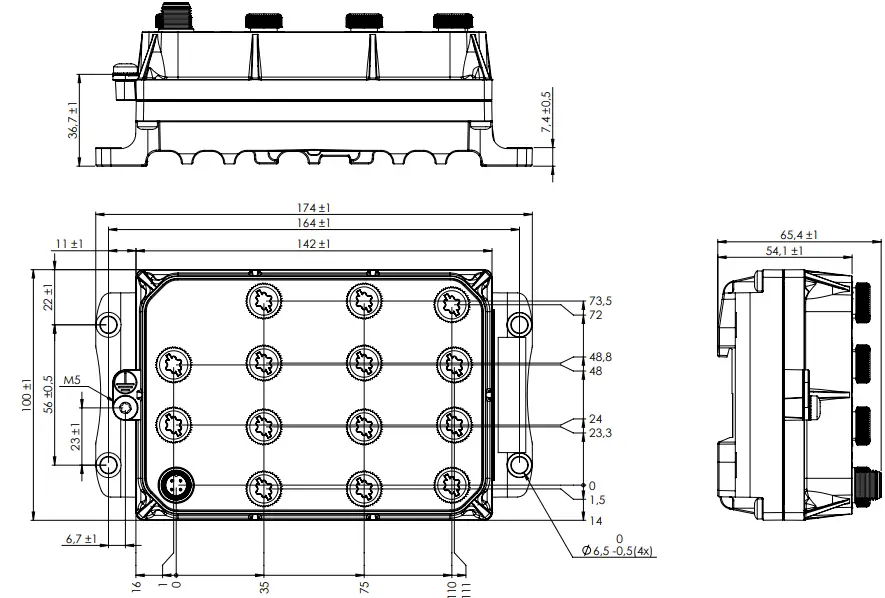
Westermo Metallverksgatan 6, SE-721 30 Västerås, Sweden Tel +46 16 42 80 00 Fax +46 16 42 80 01
E-mail: [email protected]
www.westermo.com
REV. C 6641-22410 2022-08 Westermo Network Technologies AB, Sweden


