![]()

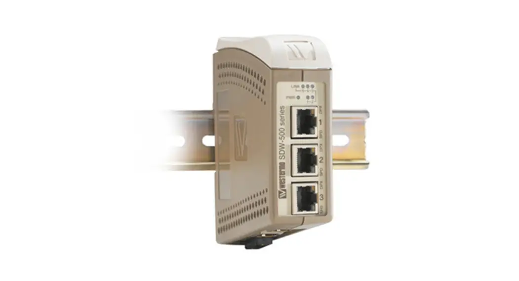
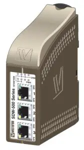
SDW-500
SDW-541-F1G-T4G & SDW-550-T5G
Industrial Ethernet 5-port Switch
General information
Legal information
The contents of this document are provided “as is”. Except as required by applicable law, no warranties of any kind, either express or implied, including, but not limited to, the
implied warranties of merchantability and fitness for a particular purpose, are made in relation to the accuracy and reliability or contents of this document. Westermo reserves the right to revise this document or withdraw it at any time without prior notice.
Under no circumstances shall Westermo be responsible for any loss of data or income or any special, incidental, and consequential, or indirect damages howsoever caused.
More information about Westermo can be found at www.westermo.com
About This Guide
This guide is intended for installation engineers and users of the Westermo products.
It includes information on safety and regulations, a product description, installation instructions, and technical specifications.
Safety and Regulations
Warning signs are provided to prevent personal injuries and/or damages to the product.
The following levels are used:
| Level of warning | Description | Consequence personal injury | Consequence material damage |
| Indicates a potentially hazardous situation | Possible death or major injury | Major damage to the product |
| Indicates a potentially hazardous situation | Minor or moderate injury | Moderate damage to the product |
| Provides information in order to avoid misuse of the product, confusion, or misunderstanding | No personal injury | Minor damage to the product |
| Used for highlighting general, but important information | No personal injury | Minor damage to the product |
Safety Information
Before installation:
Read this manual completely and gather all information on the product. Make sure that you understand it fully. Check that your application does not exceed the safe operating
specifications for this product.
![]() WARNING – SAFETY DURING INSTALLATION
WARNING – SAFETY DURING INSTALLATION
The product must be installed and operated by qualified service personnel and installed into an apparatus cabinet or similar, where access is restricted to service personnel only.
During installation, ensure a protective earthing conductor is first connected to the protective earthing terminal (only valid for metallic housings). Westermo recommends a cross-sectional area of at least 4 mm2.
If the product does not have a protective earthing terminal, then the DIN-rail must be connected to the protective earth. Upon removal of the product, ensure that the protective earthing conductor, or the connection to earth via the DIN-rail, is disconnected last.
![]() WARNING – HAZARDOUS VOLTAGE
WARNING – HAZARDOUS VOLTAGE
Do not open an energized product. Hazardous voltage may occur when connected to a power supply.
![]() WARNING – PROTECTIVE FUSE
WARNING – PROTECTIVE FUSE
The power supply wiring must be sufficiently fused. It must be possible to disconnect manually from the power supply. Ensure compliance with national installation regulations.
Replacing the internal fuse must only be performed by Westermo qualified personnel.
![]() WARNING – REDUCE THE RISK OF FIRE
WARNING – REDUCE THE RISK OF FIRE
To reduce the risk of fire, use only telecommunication line cords with a cable diameter of AWG 26 or larger. Regarding power cable dimensions, see Interface Specifications.
![]() CAUTION – CLASS 1 LASER PRODUCT
CAUTION – CLASS 1 LASER PRODUCT
Do not look directly into a fiber optical port or any connected fiber, although the product is designed to meet the Class 1 Laser regulations and complies with 21 CFR 1040.10 and 1040.11.
![]() CAUTION – FIBRE OPTIC HANDLING
CAUTION – FIBRE OPTIC HANDLING
Fiber optic equipment needs special treatment. It is very sensitive to dust and dirt. If the fiber is disconnected from the product, the protective plugs on the transmitter/receiver must be connected.
The protective plugs must be kept on during transportation. The fiber optics cables must be handled the same way.
![]() CAUTION – CORROSIVE GASES
CAUTION – CORROSIVE GASES
If the product is placed in a corrosive environment, it is important that all unused connector sockets are protected with a suitable plug, in order to avoid corrosion attacks on the gold-plated connector pins.
![]() CAUTION – ELECTROSTATIC DISCHARGE (ESD)
CAUTION – ELECTROSTATIC DISCHARGE (ESD)
Prevent electrostatic discharge damages to internal electronic parts by discharging your body to a grounding point (e.g. use a wrist strap).
Care recommendations
Follow the care recommendations below to maintain the full operation of the product and to fulfill the warranty obligations:
- Do not drop, knock or shake the product. Rough handling above the specification may cause damage to internal circuit boards.
- Use a dry or slightly water-damp cloth to clean the product. Do not use harsh chemicals, cleaning solvents or strong detergents.
- Do not paint the product. Paint can clog the product and prevent proper operation.
If the product is used in a manner not according to specification, the protection provided by the equipment may be impaired.
If the product is not working properly, contact the place of purchase, nearest Westermo distributor office or Westermo technical support.
Cleaning of the optical connectors
In the event of contamination, the optical connectors should be cleaned by the use of forced nitrogen and some kind of cleaning stick.
Recommended cleaning fluids:
- Methyl-, ethyl-, isopropyl- or isobutyl-alcohol
- Hexane
- Naphtha
Product disposal
![]()
This symbol means that the product shall not be treated as unsorted municipal waste when disposing of it. It needs to be handed over to an applicable collection point for
recycling electrical and electronic equipment.
By ensuring the product is disposed of correctly, you will help to reduce hazardous substances and prevent potential negative consequences to both environment and human
health, which could be caused by inappropriate disposal.
Simplified EU declaration of conformity
Hereby, Westermo declares that the equipment is in compliance with EU directives.
The full EU declaration of conformity and other detailed information are available at the respective product page at www.westermo.com.
Agency approvals and standards compliance
| Type | Approval / Compliance |
| EMC | EN 50121-4, Railway applications – Electromagnetic compatibility – Emission and immunity of the signaling and telecommunications apparatus |
| EN 61000-6-1, Immunity residential environments | |
| EN 61000-6-2, Immunity industrial environments | |
| EN 61000-6-4, Emission industrial environments | |
| Safety | UL 60950-1, IT-equipment |
| Marine | DNV GL rules for classification – Ships and offshore units |
| Environmental | NEMA TS 2-2003 |
DNV GL rules for classification
Type | Temperature | Humidity | Vibration | EMC | Enclosure |
| SDW-541-F1G-T4G SDW-550-T5G | D | B | B | B | A/IP21 |
Corrosive environment:
This product has been successfully tested in a corrosion test according to IEC 60068-2-60, method 3. This means that the product meets the requirements to be placed in an environment classified as ISA-S71.04 class G3 and G4.
![]() CAUTION – CORROSIVE GASES
CAUTION – CORROSIVE GASES
If the product is placed in a corrosive environment, it is important that all unused connector sockets are protected with a suitable plug, in order to avoid corrosion attacks on the gold-plated connector pins.
Type tests and environmental conditions
Environmental phenomena | Basic standard | Description | Test levels |
| ESD | EN 61000-4-2 | Enclosure | Contact: ±6 kV Air: ±8 kV |
| Fast transients | EN 61000-4-4 | Power port | ±2 kV |
| Signal ports | ±2 kV | ||
| Surge | EN 61000-4-5 | Power port | Line to earth: ±2 kV Line to line: ±1 kV |
| Signal ports | Line to earth: ±2 kV Line to line: ±1 kV | ||
| Power frequency magnetic field | EN 61000-4-8 | Enclosure | 300 A/m; 0, 16.7, 50 Hz |
| Pulsed magnetic field | EN 61000-4-9 | Enclosure | 300 A/m |
| Radiated RF immunity | EN 61000-4-3 | Enclosure | 20 V/m @ (80 – 2700) MHz 10 V/m @ (2700 – 6000) MHz 1 kHz sine, 80% AM |
| Conducted RF immunity | EN 61000-4-6 | Power port | 10 V, 80% AM, 1 kHz; (0.15 – 80) MHz |
| Signal ports | 10 V, 80% AM, 1 kHz; (0.15 – 80) MHz | ||
| Radiated RF emission | CISPR 16-2-3 | Enclosure | Class B (30 – 6000 MHz) |
| ANSI C63,4 (FCC Part 15) | Class B (30 – 6500 MHz) | ||
| Conducted RF emission | CISPR 16-2-1 | Power port | Class B |
| Signal ports | Class B | ||
| Dielectric strength | UL 60950-1 | Power interface to all other | 1.5kV AC @ 60s duration |
| TX signal interface to all other | 1.5kV AC @ 60s duration | ||
| TX shield interface to all other | 1.5kV AC @ 60s duration | ||
| Environmental | |||
| Temperatures | EN 60068-2-1 EN 60068-2-2 | Operating | –40 to +74 °C (–40 to +165 °F) |
| Storage and transport | –50 to +85 °C (–58 to +185 °F) | ||
| Relative humidity | EN 60068-2-30 | Operating | 5 to 95 % (non-condensing) |
| Storage and transport | 5 to 95 % (condensation allowed outside packaging) | ||
| Altitude | Operating | 2 000 m/70 kPa | |
| Service life | Operating | 10 year | |
| Reliability prediction (MTBF) | MIL-HDBK- 217F-N2 | Operating | SDW-541-F1G-T4G: 1.182.000 hours SDW-550-T5G: 1.121.000 hours |
| Vibration | IEC 60068-2-6 (sine) | Operating | 5–9 Hz ±6 mm 9–500 Hz ±2 g |
| Shock | IEC 60068-2-27 | Operating | 15 g, 11 ms |
| Mechanical | |||
| Enclosure | UL94 | Plastic | Flammability Class V-0 |
| Dimension W x H x D | 34 x 123 x 121 mm | ||
| Weight | 0.2 kg | ||
| Mounting | DIN-rail | ||
| Degree of protection | EN 60529 | Enclosure | IP21 |
| Cooling | Convection | ||
Configuration
Auto configured (auto-negotiation) or manually setting of speed and duplex of individual TX port, by DIP-switches. Port mirror function is possible to set with DIP-switch. With the port mirror function active the switch will copy all outgoing traffic to port 1. This can be used to monitor all traffic going out from the switch. Packets may be discarded if the total throughput exceeds the port speed of port 1.
Description
The SDW-541-F1G-T4G is an unmanaged 5-port switch with one SFP fiber port supporting 100 Mbit/s or Gbit Ethernet, and four copper ports supporting 10/100 Mbit/s or Gbit Ethernet. The Westermo range of 100 Mbit or Gbit Small Form-factor Pluggable (SFP) transceivers are available as multimode, single-mode, or Bi-Di transceivers with
distance up to 120 km.
The SDW-550-T5G is an unmanaged 5-port switch with five copper ports, all supporting 10 Mbit/s, 100 Mbit/s, or Gbit Ethernet. Both are designed for easy use in heavy-duty industrial, maritime, and rail trackside applications. The units support 802.1Q long packets which allow all standard industrial Ethernet protocols to be used.
The units are designed for use in industrial applications with dual 9.6 to 57.6 VDC power input. The unique “tri-galvanic” isolation provides isolation between all ports, power supply, and between each chassis screen avoiding ground loop currents. The IP21 rating ensures that the unit can be installed in locations where condensed water may occur. Only industrial grade components are used which gives an MTBF of 1.182.000 hours for the SDW-541-F1T4G and 1.121.000 hours for the SDW-550-T5G and thus ensures a long service life. A wide operating temperature range of –40 to +74 °C (–40 to +165 °F) can be achieved with no moving parts.
The units have been tested both by Westermo and external test houses to meet EMC, isolation, vibration, and shock standards, all to the highest levels suitable for heavy industrial, trackside, and maritime environments.
Network diagnostics are simplified with the inclusion of port mirroring on one port allowing data flow through the switch to be monitored using a network analyzer. All five ports can have data rate and flow control locked by DIP switch which can eliminate problems with old legacy Ethernet equipment that is unable to support auto-negotiation.
Interface specifications
| Power | |
| Operating voltage | Rated: 12 to 48 VDC Operating: 9.6 to 57.6 VDC |
| Rated current | SDW-541-F1G-T4G: 12-48 VDC; 260–65mA SDW-550-T5G: 12-48 VDC; 260–65mA |
| Rated frequency | DC |
| Inrush current, I2t | 22.7·10-3 A2s @ 48 VDC |
| Startup current* | 2 x Rated current |
| Polarity | Reverse polarity protected |
| Redundant power input | Yes |
| Isolation to | All other |
| Connection | Detachable screw terminal |
| Connector size | 0.2 – 2.5 mm2 (AWG 24 – 12) |
| Shielded cable | Not required |
* External supply current capability for proper start-up
| Ethernet TX | |
| Electrical specification | IEEE std 802.3. 2005 Edition |
| Data rate | 10 Mbit/s, 100 Mbit/s, 1000 Mbit/s manual or auto |
| Duplex | Full or half, manual or auto |
| Circuit type | TNV-1 |
| Transmission range | Up to 150 m with CAT5e cable or better* |
| Isolation to | All other |
| Connection | RJ-45, auto MDI/MDI-X |
| Shielded cable | Not required, except when installed in Railway applications as signaling and telecommunications apparatus and located close to rails.** |
| Conductive housing | Yes |
| Number of ports | SDW-541-F1G-T4G: 4 SDW-550-T5G: 5 |
* Refer to Safety section.
** To minimize the risk of interference, a shielded cable is recommended when the cable is located inside a 3 m boundary or the cable is longer than 30 m and inside a 10 m boundary to the rails and connected to this port.
| Ethernet SFP pluggable connections (FX or TX) (SDW-541-F1G-T4G) | |
| Electrical specification | IEEE std 802.3. 2005 Edition |
| Data rate | 100 Mbit/s or 1000 Mbit/s transceivers supported |
| Duplex | Full or Auto, depending on the transceiver |
| Transmission range | Depending on transceiver |
| Connection | SFP slot holding fiber transceiver or copper transceiver |
| Number of ports | SDW-541-F1G-T4G: 1 |
Connections
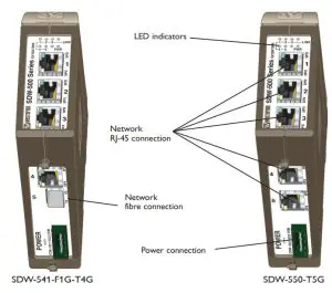
Available models:
SDW-541-F1G-T4G 10/100/1000Base-T/TX: 4 ports, 100/1000Base-FX: 1 port
SDW-550-T5G 10/100/1000Base-T/TX: 5 ports
Power
The SDW-500 series supports a redundant power connection. The positive inputs are +DC1 and +DC2, the negative inputs for both supplies are COM. The power is drawn from the input with the highest voltage.
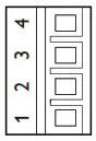
| 4-pos screw terminal | Description | Power |
| 1 | COM | 0 V |
| 2 | +DC1 | 9.6–57.6 VDC |
| 3 | +DC2 | 9.6–57.6 VDC |
| 4 | COM | 0 V |
TX
Ethernet TX connection (RJ-45 connector), automatic MDI/MDI-X crossover.
Contact | Direction | Description/Remark |
| 1 | In/Out | BI_DA+ |
| 2 | In/Out | BI_DA- |
| 3 | In/Out | BI_DB+ |
| 4 | In/Out | BI_DC+ |
| 5 | In/Out | BI_DC- |
| 6 | In/Out | BI_DB- |
| 7 | In/Out | BI_DD+ |
| 8 | In/Out | BI_DD- |
| Shield | In/Out | Connected to PE |
CAT 5 cable is recommended.
Unshielded (UTP) or shielded (STP) connector might be used.
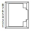
F1G, 1 SFP slot
The F1G interface has one SFP slot supporting Ethernet 100/1000
BaseFX/X. Each slot can hold one SFP transceiver for copper or fiber cable. For supported transceivers see the SFP transceivers user guide (art no. 6100-0000) available at www.westermo.com.
LED indicators
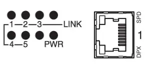
Indicators (LED)
Power (PWR)
Link (LINK) of every port
Speed (SPD) and duplex (DPX) of TX ports
LED | Status | Description |
| PWR | ON | Internal power, initializing OK |
| Slow flash | Initialization progressing | |
| Fast flash | Initialization error | |
| LINK/SPD | OFF | No Ethernet link |
| ON | Good Ethernet link | |
| Flash | Ethernet data is transmitted or received, traffic indication | |
| Flash 3 Hz | 10 Mbit/s | |
| Flash 6 Hz | 100 Mbit/s | |
| Flash 12 Hz | 1000 Mbit/s | |
| OFF | Half-duplex | |
| (TX only) | ON | Full duplex |
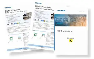
SFP Transceivers
The product supports Westermo labeled transceivers only.
See Westermo’s modular transceivers datasheets 100 Mbit and 1 Gbit for supported
SFP transceivers. See Transceiver User Guide “6100-0000” for transceiver handling instructions.
Installation
Mounting / Removal
 WARNING – HAZARDOUS VOLTAGE
Do not open an energized product. Hazardous voltage may occur when connected to a power supply.
![]() CAUTION – ELECTROSTATIC DISCHARGE (ESD)
CAUTION – ELECTROSTATIC DISCHARGE (ESD)
Prevent electrostatic discharge damages to internal electronic parts by discharging your body to a grounding point (e.g. use a wrist strap).
Mounting
This product should be mounted on a 35 mm DIN-rail which is horizontally mounted on a wall or cabinet backplate.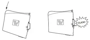
Cooling
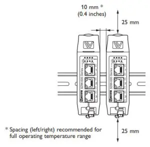
This unit uses convection cooling.
To avoid obstructing the airflow around the unit, use the following spacing rules. Minimum spacing 25 mm (1.0 inch) above / below and 10 mm (0.4 inches) left / right the unit.
Spacing is recommended for the use of the unit in the full operating temperature range and service life. CLICK!
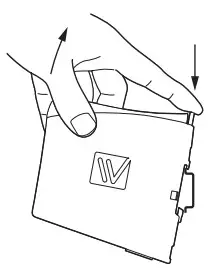
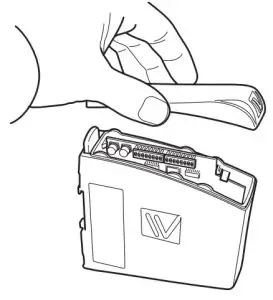
Removal Press down the black support at the back of the product, see figure.
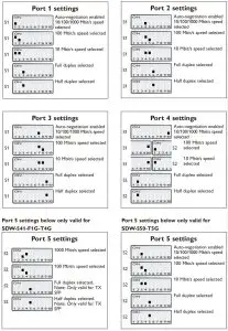
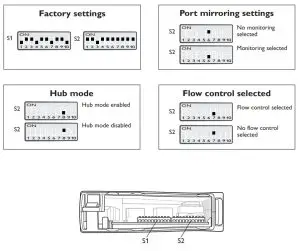
DIP switch settings
DIP switches are accessible under the lid on top of the unit. DIP switches are used to configure the unit.
![]() WARNING – HAZARDOUS VOLTAGE
WARNING – HAZARDOUS VOLTAGE
Do not open an energized product. Hazardous voltage may occur when connected to a power supply.
![]() CAUTION – ELECTROSTATIC DISCHARGE (ESD)
CAUTION – ELECTROSTATIC DISCHARGE (ESD)
Prevent electrostatic discharge damages to internal electronic parts by discharging your body to a grounding point (e.g. use a wrist strap).
NOTE
When configuration via DIP-switches, the settings of DIP-switches configure the unit only after a reboot (power off/on).
Observe this when the DIP switches are configured
… Speed and duplex setting only valid when auto-negotiation is disabled.
… When monitoring selected all outgoing packets from the switch are also copied to port 1.
… Speed and duplex switch settings are ignored for FX ports.
… If auto-negotiation and auto MDI/MDI-X are disabled all TX ports support MDI-X configuration.
… If Hub mode is selected, all incoming and outgoing packets are distributed on all other ports.
 ONLY VALID FOR SDW-541-F1G-T4G
… Speed and duplex switch settings are ignored for FX ports.
… If auto-negotiation and auto MDI/MDI-X are disabled all TX ports support MDI-X configuration.
Port settings
Westermo • SE-635 35 Stora Sundby, Sweden
Tel +46 16 42 80 00 Fax +46 16 42 80 01
E-mail: [email protected]
www.westermo.com


