![]()
 Lynx L206-F2G-EX
Industrial Ethernet 6-port Switch![]()
General information
Legal information
The contents of this document are provided “as is”. Except as required by applicable law, no warranties of any kind are made in relation to the accuracy and reliability or contents of this document, either expressed or implied, including but not limited to the implied warranties of merchantability and fitness for a particular purpose. Westermo reserves the right to revise this document or withdraw it at any time without prior notice.
Under no circumstances shall Westermo be responsible for any loss of data or income or any special, incidental, and consequential or indirect damages howsoever caused.
More information about Westermo can be found at www.westermo.com
Software tools
Related software tools are available at www.westermo.com/support/software-tools.
License and copyright for included Free/Libre Open Source Software
This product includes software developed by third parties, including Free/Libre Open Source Software (FLOSS). The specific license terms and copyright associated with the software are included in each software package respectively. Please visit the product web page for more information.
Upon request, the applicable source code will be provided. A nominal fee may be charged to cover shipping and media. Please direct any source code request to your normal sales or support channel.
WeOS Management Guide
This product runs WeOS (Westermo Operation System). Instructions for quick start, configuration, factory reset and use of USB port are found in the WeOS Management
Guide at www.westermo.com.
Safety and Regulations
Warning signs are provided to prevent personal injuries and/or damages to the product.
The following levels are used:
Level of warning | Description | Consequence personal injury | Consequence material damage |
| Indicates a potentially hazardous situation | Possible death or major injury | Major damage to the product |
| Indicates a potentially hazardous situation | Minor or moderate injury | Moderate damage to the product |
| Provides information in order to avoid misuse of the product, confusion or misunderstanding | No personal injury | Minor damage to the product |
| Used for highlighting general, but important information | No personal injury | Minor damage to the product |

Before installation:
Read this manual completely and gather all information on the product. Make sure that you understand it fully. Check that your application does not exceed the safe operating specifications for this product.
 WARNING – SAFETY DURING INSTALLATION
The product must be installed by qualified service personnel and built into an apparatus cabinet or similar, where access is restricted to service personnel only.
During installation, ensure a protective earthing conductor is first connected to the protective earthing terminal (only valid for metallic housings). Westermo recommends a cross-sectional area of at least 4 mm2.
If the product does not have a protective earthing terminal, then the DINrail must be connected to the protective earth. Upon removal of the product, ensure that the protective earthing conductor, or the connection to earth via the DIN-rail, is disconnected last.
WARNING – HAZARDOUS VOLTAGE
Do not open an energized product. Hazardous voltage may occur when connected to a power supply.
WARNING – PROTECTIVE FUSE
It must be possible to disconnect manually from the power supply.
Ensure compliance with national installation regulations. Replacing the internal fuse must only be performed by Westermo qualified personell.
WARNING – POWER SUPPLY CONNECTION
There are safety regulations on which power sources shall be used in conjunction with the product. Refer to Interface Specifications.
WARNING – REDUCE THE RISK OF FIRE
To reduce the risk of fire, use only telecommunication line cords with a cable diameter of AWG 26 or larger. Regarding power cable dimensions, see Interface Specifications.
 CAUTION – CLASS 1 LASER PRODUCT
Do not look directly into a fiber optical port or any connected fiber, although the product is designed to meet the Class 1 Laser regulations and complies with 21 CFR 1040.10 and 1040.11.
CAUTION – HANDLING OF SFP TRANSCEIVERS
SFP transceivers are supplied with plugs to avoid contamination inside the optical port. They are very sensitive to dust and dirt. If the fiber is disconnected from the product, the protective plugs on the transmitter/receiver must be connected. The protective plugs must be kept on during transportation. The fiber optics cables must be handled the same way.
CAUTION – CORROSIVE GASES
If the product is placed in a corrosive environment, it is important that all unused connector sockets are protected with a suitable plug, in order to avoid corrosion attacks on the gold-plated connector pins.
CAUTION – ELECTROSTATIC DISCHARGE (ESD)
Prevent electrostatic discharge damages to internal electronic parts by discharging your body to a grounding point (e.g. use a wrist strap).
CAUTION – HOT SURFACE
Be aware of that the surface of this product may become hot.
When it is operated at high temperatures, the external surface may exceed the Touch Temperature Limit according to the product’s relevant electrical safety standard.
CAUTION – CABLE TEMPERATURE RATING FOR FIELD TERMINAL WIRES
There may be a requirement on the minimum temperature rating of the cable to be connected to the field wiring terminals, see Interface Specifications.
Care recommendations
Follow the care recommendations below to maintain the full operation of the product and to fulfill the warranty obligations:
- Do not drop, knock or shake the product. Rough handling above the specification may cause damage to internal circuit boards.
- Use a dry or slightly water-damp cloth to clean the product. Do not use harsh chemicals, cleaning solvents or strong detergents.
- Do not paint the product. Paint can clog the product and prevent proper operation.
If the product is used in a manner not according to specification, the protection provided by the equipment may be impaired.
If the product is not working properly, contact the place of purchase, nearest Westermo distributor office or Westermo technical support.
Product disposal
 This symbol means that the product shall not be treated as unsorted municipal waste when disposing of it. It needs to be handed over to an applicable collection point for recycling electrical and electronic equipment. By ensuring this product is disposed of correctly, you will help to reduce hazardous substances and prevent potential negative consequences to both environment and human health, which could be caused by inappropriate disposal.
![]() ATEX certification
ATEX certification
ATEX certification number
Baseefa12ATEX0119X
Standards
EN 60079-0, EN 60079-15
Certification code
Ex nA IIC T3 Gc (-40°C ≤ Ta ≤ +70°C)
ATEX code![]() II 3G
II 3G
Specific Conditions of Use
The equipment must be installed in an area of not more than pollution degree 2 in accordance with IEC/EN 60664-1, and in an enclosure that provides a minimum degree of protection of at least IP54 and complies with the relevant requirements of EN 60079-0 and EN 60079-15.
All external connections to the equipment and, where applicable, the SFP modules must not be inserted or removed unless either the area in which the equipment is installed is known to be non-hazardous, or the circuits connected have been de-energized.
The network cables once installed must be properly fixated by the use of cable ties or similar to reduce the risk of accidentally withdrawing the plugs.
Equipment input parameters
Power Connector: +DC1, +DC2 & -COM
Working Voltage Range = 24 V to 48 VDC.
I/O Connector: ‘Status +’ & ‘Status -’ and ‘Digital in +’ and ‘Digital in -’
Maximum I/P Voltage = 60 VDC.
![]() SFP option approved transceivers
SFP option approved transceivers
| SFP Transceivers, 100 Mbit | |
| 1100-0131 | MLC2, Multimode, LC-Connector, 2 km, 1310 nm |
| 1100-0132 | SLC20, Singlemode, LC-Connector, 20 km, 1310 nm |
| 1100-0133 | SLC40, Singlemode, LC-Connector, 40 km, 1310 nm |
| 1100-0134 | SLC80, Singlemode, LC-Connector, 80 km, 1550 nm |
| 1100-0140 | SLC120, Singlemode, LC-Connector, 120 km, 1550 nm |
| BiDi Transceivers, 100 Mbit | |
| 1100-0145 | SLC15-BiDi-A, Singlemode, BiDi, 20 km, 1310 nm TX, 1550 nm RX |
| 1100-0146 | SLC15-BiDi-B, Singlemode, BiDi, 20 km, 1550 nm TX, 1310 nm RX |
| 1100-0152 | MLC2-BiDi-A, Multimode, BiDi, 2 km, 1310 nm TX, 1550 nm RX |
| 1100-0153 | MLC2-BiDi-B, Multimode, BiDi, 2 km, 1550 nm TX, 1310 nm RX |
| SFP Transceivers, 1 Gbit | |
| 1100-0144 | GMLC550-SX, Multimode, LC-Connector, 550 m, 850 nm, SX |
| 1100-0147 | GMLC2-SX+, Multimode, LC-Connector, 2 km, 1310 nm, SX+ |
| 1100-0141 | GSLC10-LX, Singlemode, LC-Connector, 10 km, 1310 nm, LX |
| 1100-0142 | GSLC50-XD, Singlemode, LC-Connector, 50 km, 1550 nm, XD |
| 1100-0143 | GSLC80-ZX, Singlemode, LC-Connector, 80 km, 1550 nm, ZX |
| 1100-0171 | GSLC110-EZX, Singlemode, LC-Connector, 110 km, 1550 nm, EZX |
| BiDi Transceiver, 1 Gbit | |
| 1100-0156 | GSLC20-BiDi-A, Singlemode, BiDi, 20 km, 1310 nm TX, 1490 nm RX |
| 1100-0157 | GSLC20-BiDi-B, Singlemode, BiDi, 20 km, 1490 nm TX, 1310 nm RX |
| Copper Transceiver, 1 Gbit | |
| 1100-0148 | GC100, Copper, RJ45, 100 m, 1000BaseT |
Agency approvals and standards compliance
Type | Approval / Compliance |
| EMC | EN 61000-6-1, Immproducty residential environments |
| EN 61000-6-2, Immproducty industrial environments | |
| EN 61000-6-3, Emission residential environments | |
| EN 61000-6-4, Emission industrial environments | |
| EN 50121-4, Railway signaling and telecommunications apparatus | |
| IEC 62236-4, Railway signaling and telecommunications apparatus | |
| Safety | UL 62368-1, Safety Communication Technology |
| Marine | DNV GL rules for classification – Ships and offshore products |
| Ex | EN 60079-0, EN 60079-15 |
UL 62368-1 Notice:
This product has been tested and found compliant to UL 62368-1, Safety for Communication Technology. In accordance with the definitions of the standard, this product shall be handled by instructed personell. Energy source classifications are according to the following:
| Electrical energy source | Power port | ES1 |
| Serial port | ES1 | |
| Ethernet port | ES1, TNV-1 | |
| I/O port | ES1 | |
| Power source | Power port | PS3 |
| Thermal energy source | Enclosure | TS1 |
| Mechanical energy source | Enclosure | MS1 |
| Radiation energy source | SFP | RS1 |
FCC Part 15.105 Notice:
This equipment has been tested and found to comply with the limits for a Class A digital device, pursuant to Part 15 of the FCC Rules. These limits are designed to provide reasonable protection against harmful interference when the equipment is operated in a commercial environment. This equipment generates, uses, and can radiate radio frequency energy and, if not installed and used in accordance with the instruction manual, may cause harmful interference to radio communications. Operation of this equipment in a residential area is likely to cause harmful interference in which case the user will be required to correct the interference at his own expense.
Corrosive environment Notice:
This product has been successfully tested in a corrosion test according to IEC 60068-260, method 3. This means that the product meets the requirements to be placed in an environment classified as ISA-S71.04 class G3.
CAUTION – CORROSIVE GASES
If the product is placed in a corrosive environment, it is important that all unused connector sockets are protected with a suitable plug, in order to avoid corrosion attacks on the gold plated connector pins.
Declaration of Conformity
Hereby, Westermo declares that this product is in compliance with applicable EU directives. The full EU declaration of conformity and other detailed information is available at www.westermo.com/support/product-support.
Product Description
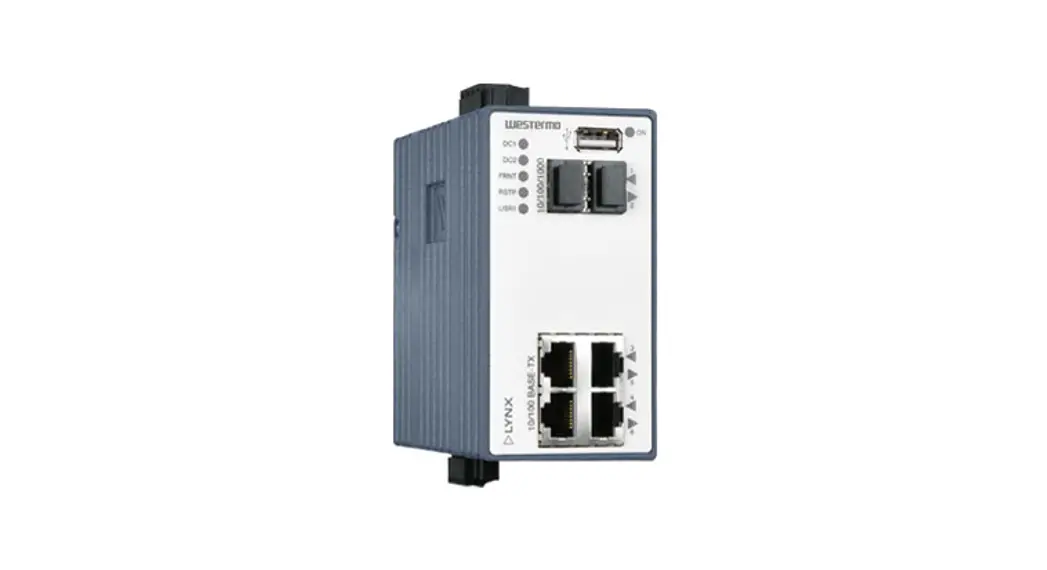
L206-F2G-EX is an industrial switch made for harsh environments. The switch can be used in either 100 Mbit or Gigabit networks due to our multi-rate SFP solution. L206- F2G-EX can also be used together with our previous Lynx series of switches.
Our unique FRNT (Fast Recovery of Network Topology) technology is the fastest protocol on the market to re-configure a network in the event of any link or hardware failure. That is why our products are used in safety-critical applications such as tunnels, traffic signal control, and railway systems.
Installations in harsh environments and places with heavy electrical interference require the use of reliable media. Lynx provides a number of solutions using fiber optic transceivers.
Multi- or single-mode transceivers can be used to build point-to-point or redundant ring networks with ranges up to 120 km between each switch. Our BIDI transceiver, which transmits and receives data on a single fiber can be used in applications where the number of fiber cores is limited.
Real-time properties are implemented in the switch in order to achieve determinism for real-time-critical applications. Lynx supports QoS (Quality of Service) with four priority queues and strict priority scheduling as well as HoL (Head of Line Blocking Prevention).
All to assure that the data network is deterministic.
Hardware Overview
Location of interface ports and LEDs
Interface specifications
Power | |
| Operating voltage | Rated: 24 to 48 VDC Operating: 19 to 60 VDC |
| Rated current | 180 mA (330 mA) @ 24 VDC (with 500 mA USB load) 90 mA (170 mA) @ 48 VDC (with 500 mA USB load) |
| Rated frequency | DC |
| Inrush current, I2t | 22.7·10-3 A2s @ 48 VDC |
| Startup current* | 2 x Rated current |
| Polarity | Reverse polarity protected |
| Redundant power input | Yes |
| Isolation to | All other ports |
| Connection | Detachable screw terminal |
| Conductor cross section | 0.2 – 2.5 mm2 (AWG 24 – 12) |
| Stripping length cable | 7 mm |
| Tightening torque, terminal screw | 0.5 -0.6 Nm |
| Tightening torque, screw flange | 0.3 Nm |
| Shielded cable | Not required |
* Recommended external supply current capability for proper startup
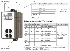
Ethernet TX | |
| Electrical specification | IEEE std 802.3 |
| Data rate | 10 Mbit/s, 100 Mbit/s, manual or auto |
| Duplex | Full or half, manual or auto |
| Circuit type | TNV-1 |
| Transmission range | Up to 150 m with CAT5e cable or better* |
| Isolation to | All other ports |
| Connection | RJ-45, auto MDI/MDI-X |
| Shielded cable | Not required, except when installed in Railway applications as signaling and telecommunications apparatus and located close to rails.** |
| Conductive housing | Yes |
| Number of ports | 4 |
* Refer to Safety section.
** To minimize the risk of interference, a shielded cable is recommended when the cable is located inside a 3 m boundary or the cable is longer than 30 m and inside a 10 m boundary to the rails and connected to this port.
Ethernet SFP pluggable connections (FX or TX) | |
| Electrical specification | IEEE std 802.3 |
| Data rate | 100 Mbit/s or 1000 Mbit/s transceivers supported |
| Duplex | Full or Auto, depending on the transceiver |
| Transmission range | Depending on tranceiver |
| Connection | SFP slot holding fiber transceiver or copper transceiver |
| Number of ports | 1 or 2 |
I/O / Relay output | |
| Maximum voltage/current | 60 VDC / 80 mA |
| Contact resistance | Max 30 Ω |
| Isolation to | All other ports |
| Connection | Detachable screw terminal |
| Conductor cross section | 0.14 – 1.5 mm2 (AWG 28 – 16) |
| Stripping length cable | 7 mm |
| Tightening torque, terminal screw | 0.22 -0.25 Nm |
| Tightening torque, screw flange | 0.3 Nm |
I/O / Digital input | |
| Maximum voltage/load current | 60 VDC / 2 mA |
| Voltage levels | Logic one: >12V Logic zero: <1V |
| Isolation to | All other |
| Connection | Detachable screw terminal |
| Conductor cross section | 0.14 – 1.5 mm2 (AWG 28- 16) |
| Stripping length cable | 7 mm |
| Tightening torque, terminal screw | 0.22 -0.25 Nm |
| Tightening torque, screw flange | 0.3 Nm |
USB | |
| Electrical specification | USB 2.0 host interface |
| Data rate | Up to 12 Mbit/s (full-speed mode) |
| Circuit type | SELV |
| Maximum supply current | 400 mA |
| Connection | USB receptacle connector type A |
Console | |
| Electrical specification | TTL-level |
| Data rate | 115.2 kbit/s |
| Data format | 8 data bits, no parity, 1 stop bit, no flow control |
| Circuit type | SELV |
| Connection | 2.5 mm jack, use only Westermo cable 1211-2027 |
SFP Transceivers
The product supports UL and IEC-certified transceivers only. See Westermo’s modular transceivers datasheets 100 Mbit and 1 Gbit for supported SFP transceivers, which can be downloaded from the product support pages at www.westermo.com/support/productsupport.
Each SFP slot can hold one SFP transceiver. See “Transceiver User Guide 6100-0000” for transceiver handling instructions, which also can be downloaded from the product support pages at www.westermo.com/support/product-support.
In the event of contamination, the optical connectors in the SFP transceivers should only be cleaned by the use of forced nitrogen and some kind of cleaning stick. recommended cleaning fluids are methyl-, ethyl-, isopropyl- or isobutyl alcohol, hexane or naphtha
Supported transceivers
Firmware prior to 4.4.0 accepts Westermo branded transceivers only. From 4.5.0 other transceivers are accepted with notice and the product will no longer be UL approved.
Temp. specifications are also depending on the used transceivers.
Note: To comply with UL 62368-1, only UL recognized SFP transceivers should be used.
CAUTION – HANDLING OF SFP TRANSCEIVERS
SFP transceivers are supplied with plugs to avoid contamination inside the optical port. They are very sensitive to dust and dirt. If the fiber is disconnected from the product, the protective plugs on the transmitter/receiver must be connected. The protective plugs must be kept on during transportation. The fiber optics cables must be handled the same way.
Deviations
With copper transceiver 1100-0148, the specified operating temperature on Lynx is 0 to +50ºC (32 to +122°F). FRNT reconfiguration times can not be guaranteed with copper transceivers.
Type tests and environmental conditions
| Environmental phenomena | Basic standard | Description | Test levels | |
| ESD | EN 61000-4-2 | Enclosure | Contact: ±6 kV Air: ±8 kV | |
| Fast transients | EN 61000-4-4 | Power port | ±2 kV | |
| Signal ports | ||||
| Earth port | ±1 kV | |||
| Surge | EN 61000-4-5 | Power port | L-E: ±2 kV, 42 0, 0.5 pF, 1.2/50 ps L-L: ±2 kV, 42 0, 0.5 pF, 1.2/50 ps L-E: ±2 kV, 12 0, 9 pF, 1.2/50 ps L-L: ±1 kV, 2 0, 18 pF, 1.2/50 ps | |
| Ethernet ports | L-E: ±2 kV, 12 0, 1.2/50 ps | |||
| Power frequency magnetic field | EN 61000-4-8 | Enclosure | 300 A/m; 0, 16.7, 50 Hz | |
| Pulsed magnetic field | EN 61000-4-9 | Enclosure | 300 A/m | |
| Radiated RF immunity | EN 61000-4-3 | Enclosure | 20 V/m @ (80 – 2700) MHz 10 V/m @ (2700 – 6000) MHz 1 kHz sine, 80% AM | |
| Conducted RF immunity | EN 61000-4-6 | Power port | 10 V, 80% AM, 1 kHz; (0.15 – 80) MHz | |
| Signal ports | ||||
| Earth port | ||||
| Radiated RF emission | CISPR 16-2-3 ANSI C63.4 | Enclosure | Class A (Industrial), 30 MHz to 6 GHz FCC Part 15 B, Class A, 30 MHz to 6.5 GHz | |
| Conducted RF emission | CISPR 16-2-1 ANSI C63.4 | Power port | Class B | |
| Signal ports | ||||
| Dielectric strength Environmental Temperatures | UL 62368-1 EN 60068-2-1 EN 60068-2-2 | Power port to all other ports | 1.5 Vrms, 50 Hz, 1 min -40 to +70°C (-40 to +158°F)* | |
| Signal ports to all other ports Operating | ||||
| Storage and transport | -50 to +85°C (-58 to +185°F) | |||
| Humidity | EN 60068-2-30 | Operating | 5 to 95 % relative humidity | |
| Storage and transport | ||||
| Altitude | Operating | 2 000 m / 70 kPa | ||
| Service life | Operating | 10 years | ||
| Reliability prediction (MTBF) | MIL-HDBK- 217F | Operating | 615,000 hours | |
| Vibration | IEC 60068-2-6 (sine) | Operating | 3 – 13.2 Hz: 1mm 13.2 – 100 Hz: 0.7 g | 5.5 – 30 Hz: 1.5 g 30 – 50 Hz: 0.42 mm 50 – 500 Hz: 4.2 gn |
| Shock | IEC 60068-2-27 | Operating | 30 g, 11 ms 100 g, 6 ms•* | |
| Bump Packaging Enclosure | IEC 60068-2-27 UL 62368-1 | Operating Zinc | 10 g, 11 ms, x1000 Fire enclosure | |
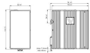
| Dimension WxHxD With connectors | 52.5 x 100 x 101 mm 52.5 x 119 x 101 mm | |||
| Weight | 0.7 kg | |||
| Degree of protection | EN 60529 | Enclosure | IP 40 | |
| Cooling | Convection | |||
** Refer to the “Safety” section.
** Might require Ethernet cables to be fastened close to the product.
Console Port
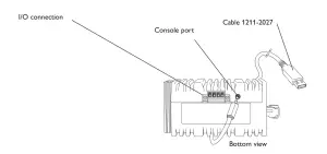
Connection to console port
The console port can be used to connect to the CLI (Command Line Interface).
The following steps need to be taken
- Connect the serial diagnostic cable to the console port (use only Westermo cable 1211-2027).
- Connect the cable to your computer (USB port, if drivers are needed they can be downloaded from our Web page).
- Use a terminal emulator and connect with the correct speed and format (115200, 8N1) to the assigned port.
For more information about the CLI, see the WeOS management guide.
Accessories | |
Description | Art no |
| Westermo console cable | 1211-2027 |
RJ45 to the terminal block | 1200-2490 |
| RJ45 to DB9 cable | 1211-2210 |
Connector Information
Power connection
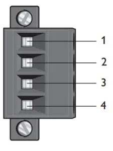 | 4-position | Product marking | Direction | Description | Input values |
| No. 1 | +DC1 | Input | Supply voltage input DC1 | Uin = (19 – 60) VDC Iin = 330 mA @ 24 VDC PIn = 8 W @ 24 VDC | |
| No. 2 | +DC2 | Input | Supply voltage input DC2 | ||
| No. 3 | -COM | Input | Common | ||
| No. 4 | -COM | Input | Common |
Lynx supports redundant power connections. The positive inputs are + DC1 and +DC2, the negative input for both supplies are -COM. Connect the primary voltage (e.g. +24 VDC) to the +DC1 pin and return to one of the -COM pins on the power input.
I/O connection
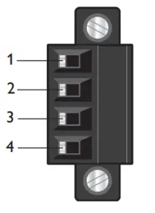 | 4-position | Product marking | Direction | Description | Input / Output values |
| No. 1 | Status + | Output | Alarm relay (status) contact | Uin = 60 VDC max | |
| No. 2 | Status – | Output | Alarm relay (status) contact | Iin = 80 mA max | |
| No. 3 | Digital in + | Input | Digital in + | Uin = 60 VDC max | |
| No. 4 | Digital in – | Input | Digital in – | Iin = 2 mA max |
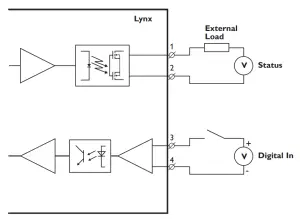
The Status output is a potential free, opto-isolated normally closed solid-state relay.
This can be configured to monitor various alarm events within the Lynx product, see WeOS Management Guide.
An external load in series with an external voltage source is required for proper functionality.
For voltage/current ratings, see the Interface Specification section.
Console port
| Position | Direction* / description | Input/output values |
| No.1 | In / out / GND | U = 3.3 VDC max I = 24 mA max |
| No. 2 | Out / Tx | |
| No. 3 | In / Rx |
The Digital in is an opto-isolated digital input that can be used to monitor external events. For voltage/current ratings, see the Interface Specification section:
LED indicators
LED | Status | Description |
| ON | OFF | The product has no power. |
| GREEN | All OK, no alarm condition. | |
| RED | Alarm condition, or until the product has started up. (Alarm conditions are configurable, see ”WeOS Management Guide”). | |
| BLINK | Location indicator (“Here I am!”). Activated when connected to IPConfig Tool, or upon request from Web or CLI. | |
| DC1 | OFF | The product has no power |
| GREEN | Voltage present on DC1* | |
| RED | No voltage present on DC1 | |
| DC2 | OFF | The product has no power |
| GREEN | Voltage present on DC2* | |
| RED | No voltage is present on DC2. | |
| FRNT | OFF | FRNT disabled. |
| GREEN | FRNT OK. | |
| RED | FRNT Error. | |
| BLINK | Product configured as FRNT Focal Point. | |
| RSTP | OFF | RSTP disabled. |
| GREEN | RSTP enabled. | |
| BLINK | Product elected as RSTP/STP root switch. | |
| USR1 | OFF | Configurable, see WeOS Management Guide. |
| GREEN | ||
| RED | ||
| 1 to 6 | OFF | No Link. |
| GREEN | Link established. | |
| GREEN FLASH | Data traffic indication. | |
| YELLOW | Port alarm and no link. Or if FRNT or RSTP mode, port is blocked. |
*Note: Supply voltage levels must be ensured externally. A green LED may not guarantee a valid operating voltage level.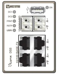
Mounting
This product should be mounted on 35 mm DIN-rail, which is horizontally mounted inside an apparatus cabinet or similar. It is recommended that the DIN-rail be connected to ground. Snap-on the product to the DIN-rail according to the figure.
Mounting Lynx with integrated DIN-clip:
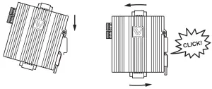
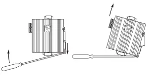
Removal
This product has an integrated DIN-clip. To remove the product, press down the support at the back with a screwdriver and lift it off the DIN-rail.
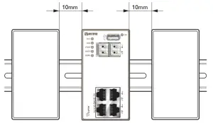
Cooling
This product uses convection cooling.
To avoid obstructing the airflow around the product, use the following spacing rules. Minimum spacing 25 mm (1.0 inch) above / below and 10 mm (0.4 inches) left / right the product.
Spacing is recommended for the use of products in full operating temperature range and service life.
Getting Started
This product runs the Westermo Operating System (WebOS) which provides several management tools that can be used for the configuration of the product.
- config tool This is a custom Westermo tool used for the discovery of attached Westermo products.
- Web Configuration of the product using the web browser.
- CLI
Configuration of the product via the Command Line Interface.
Username: admin
Password: westernmo
If the computer is located in the same subnet as the switch you can easily use a web browser to configure the product. Within the web you can configure most of the available functions.
For advanced network settings and more diagnostic information, please use the CLI. Detailed documentation is available in the chapter “The Command Line Management Tool” in the WeOS management guide. If you are not sure about the subnet – consult your network administrator.
Factory default IP address: 192.168.2.200
Netmask: 255.255.255.0
Gateway: Disabled
Configuration
Configure the product via a web browser
The product can easily be configured via a web browser. Open the link http://192.168.2.200 in your web browser, and you will be prompted with a login screen, where the default settings for username and password are:
Username: admin
Password: western
Once you have logged in, you can use the extensive integrated help function describing all configuration options. Two common tasks when configuring a new switch are to assign appropriate IP settings and to change the password of the admin account. The password can be up to 64 characters long, and should consist of printable ASCII characters (ASCII 33-126); ‘Space’ is not a valid password character.
 Note
Note
Version of IP Config tool must be 10.3.0 or higher.
Referring documents
| Type | Description | Document number |
| Management Guide | Westermo OS management guide | 6101-3201 |
Factory default on L206-F2G EX
It is possible to set the product to factory default settings by using two straight standard
Ethernet RJ-45 cables.
- Power off the switch and disconnect all Ethernet cables (copper and fiber).
- Connect one Ethernet cable between Ethernet ports 3 and 6, and the other between Ethernet ports 4 and 5.
The ports need to be connected directly by an Ethernet cable, i.e., not via a hub or switch. Use a straight cable – not a cross-over cable – when connecting the ports. - Power on the product.
- Wait for the product to start up. Control that the ON LED is flashing red.
The ON LED flashing indicates that the product is now ready to be reset to factory default. You now have the choice to go ahead with the factory reset, or to skip factory reset and boot as normal.
• Go ahead with factory reset:
Acknowledge that you wish to conduct the factory reset by unplugging the Ethernet cables. The ON LED will stop flashing.
This initiates the factory reset process*, and the product will restart with factory default settings. When the switch has booted up, the ON LED will show a green light, and is now ready to use.
• Skip the factory reset:
To skip the factory reset process, just wait for approximately 30 seconds (after the ON LED starts flashing RED) without unplugging the Ethernet cables.
The switch will conduct a normal boot with the existing settings.
Note
Do not power off the product while the factory reset process is in progress.
Dimensions
Measurements are stated in millimeters.
![]() Westermo • SE-635 35 Stora Sundby, Sweden
Westermo • SE-635 35 Stora Sundby, Sweden
Tel +46 16 42 80 00 Fax +46 16 42 80 01
E-mail: [email protected]
www.westermo.com
REV. H 6643-22001 2020-12 Westermo Network Technologies AB, Sweden


