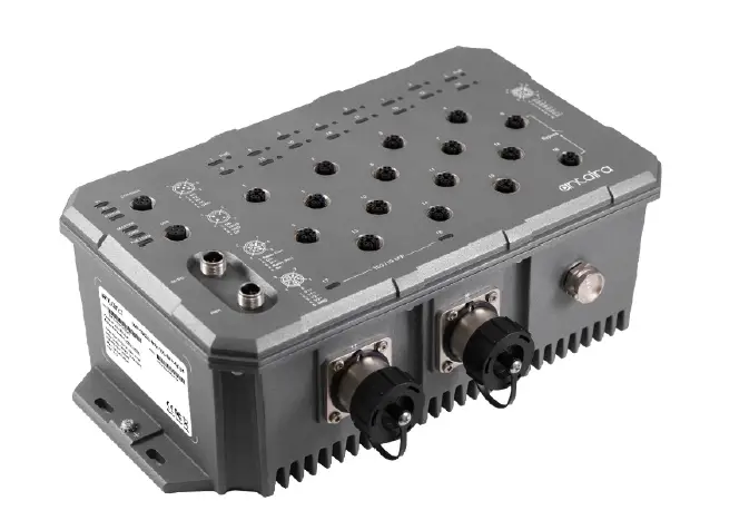
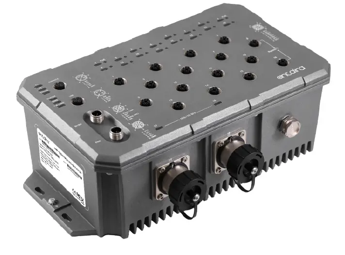
antaira LMP-1802G-M12-10G-SFP-67-24 Series 18-Port Industrial M12 IP67 Waterproof Gigabit PoE+ Light Layer 3 Managed Ethernet Switch
Tel: 1-844-268-2472 Fax: 1-714-671-9944 www.antaira.com
LMP-1802G-M12-10G-SFP-67-24 Series
18-Port Industrial M12 IP67 Waterproof Gigabit PoE+ Light Layer 3 Managed Ethernet Switch, with 16*10/100/1000Tx M12 Connectors (X-Coded) (30W/Port) and 2*1G/10G SFP Slots,
24-55VDC Power Input
Package Check List
The package contains the following items:
- 1 – Quick Installation Guide
- 1 – LMP-1802G-M12-10G-SFP-67-24(-T)
- 1 – Dust Cover Set
- 2 – SFP Metal Field Installable Cable End Lock
- 1 – SFP Removal Kit
Front Panel Layout
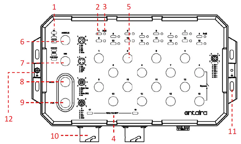
| 1 Power 1, Power 2, Status, Master, Ring, and PoE Load | 7 USB Port |
| 2 Port 1~16 Link/Active Status 10/100/1000 Mbps | 8 DI/DO Port |
| 3 Port 1~16 PoE Status | 9 Power Input Port |
| 4 Port 17~18 SFP Link/Active Status 1G/10Gbps | 10 1G/10G SFP+ Port |
| 5 10/100/1000Base-T(X) Ethernet Port | 11 Mounting hole |
| 6 Console Port | 12 Grounding screw |
Product Overview
System Interface/Performance
- All Ethernet ports support the auto MDI/MDI-X function
- M12 connector with IP67 rated protection
- Store-and-forward switching architecture
Power Input & Connection
- DC 24 to 55V redundant power
- It is recommended to use a UL listed industrial power supply
Operating Temperature
- Standard operating temperature model: -10°C to 65°C
- Extended operating temperature model: -40°C to 70°C
Case/Installation
- IP67 protection
- Wall Mount design
LED Indicators
| LED | Color | Description | |
| P1 | Green | On | Power input 1 is active |
| Off | Power input 1 is inactive | ||
| P2 | Green | On | Power input 2 is active |
| Off | Power input 2 is inactive | ||
| Status | Green | On | No event happened after the last reset or reboot |
| Red | On | 1. System booting 2. Event happened by software setting | |
| Flashing | Firmware Upgrade | ||
| Master | Green | On | ERPS Owner Mode (Ring Master) is ready |
| Off | ERPS Owner Mode is not active | ||
| Ring |
Green | On | ERPS Ring Network is active and work well |
| Flashing | ERPS Ring works abnormally or misconfigure | ||
| Off | ERPS Ring Network is not active | ||
| PoE LOAD | Off | Off | The current PoE output of all connected PDs is ≤ 50% |
| Blue | On | The current PoE output of all connected PDs is 51% ~ 70% | |
| Red | On | The current PoE output of all connected PDs is 71% ~ 90% | |
| Red | Flashing | The current PoE output of all connected PDs is 91% ~ 100% | |
| Note: The Max. PoE output of this switch is 240Watts. | |||
| LINK/ACT (Port 1~16) |
Green | On | Connected to network, 1000 Mbps |
| Flashing | Networking is active | ||
| Off | Not connected to network | ||
|
Amber | On | Connected to network, 10/100 Mbps | |
| Flashing | Networking is active | ||
| Off | Not connected to network | ||
| PoE | Amber | On | Supplying power to the powered-device |
| Off | Not connected to a Powered Device | ||
| LINK/ACT (SFP Port 17~18) |
Green | On | Connected to the network, 10Gbps |
| Flashing | Networking is active | ||
| Off | Not connected to network | ||
|
Amber | On | Connected to the network, 1Gbps | |
| Flashing | Networking is active | ||
| Off | Not connected to network | ||
Quick Installation
Ethernet Ports
M12 Ports (Auto MDI/MDI-X)
All M12 ports (8-Pin X-Coded Female Connector) are auto-sensing for 10Base-T, 100Base-TX, or 1000Base-T device connections. Please follow the wiring pin assignment table below for Ethernet port installation.
| Illustration | Pinouts | 10/100Base-T(X) Signal | 1000Base-T Signal |
 | 1 | Transmit Data + (TX+) | BI_DA+ |
| 2 | Transmit Data – (TX-) | BI_DA- | |
| 3 | Receive Data + (RX+) | BI_DB+ | |
| 4 | Receive Data – (RX-) | BI_DB- | |
| 5 | BI_DD+ | ||
| 6 | BI_DD- | ||
| 7 | BI_DC- | ||
| 8 | BI_DC+ |
NOTE: Recommended use the wire gauge between 18AWG.
Power Input Wiring
- Dual DC power inputs for power redundancy
- Connection format: M12 5-Pin K-Coded male connector
- Pin assignment of M12 power connector:
| Illustration | Pinouts | Function |
 | 1 | Power Input 1 + (V1+) |
| 2 | Power Input 1 – (V1-) | |
| 3 | Power Input 2 – (V2-) | |
| 4 | Power Input 2 + (V2+) | |
| 5 | GND |
NOTE: Recommended use the wire gauge between 24AWG.
Console Port
• Connection format: M12 5-Pin A-Coded Female Connector
• Baud rate 115,200bps, 8, N, 1
| Illustration | Pinouts | Signal |
 | 1 | NC |
| 2 | TX | |
| 3 | RX | |
| 4 | NC | |
| 5 | GND |
USB Port
- Connection format: M12 4-Pin A-Coded Female Connector
- USB Port is for configuration backup / restore
| Illustration | Pinouts | Function |
 | 1 | DN |
| 2 | VBUS | |
| 3 | GND | |
| 4 | DP |
Relay Contact and Digital Input
- Connection format: M12 5-Pin A-Coded Male Connector
- Minimum Wire Gauge: 24AWG
| Illustration | Pinouts | Function | Function |
 | 1 | DI+ Relay Com | Common |
| 2 | DI+ | Digital Input + | |
| 3 | DI- | Digital Input – | |
| 4 | DI- Relay (N.C.) | Normally Closed | |
| 5 | NA | Not Assigned |
Digital Input (DI)
The digital input is used for monitoring two external events via an external voltage source. When the voltage level on digital input pins changes from high voltage to low voltage, the DI function will be triggered. Below table is shown a detail specification of the digital input.
| Specification | Description | |
| Level 0 (Low) | -30~8VDC | Will trigger DI function (active trigger states) |
| Level 1 (High) | 10~30VDC | Normal Status (inactive trigger states) |
| Nominal input voltage | 24VDC | |
| Max. input voltage | 30VDC | |
| Nominal input current | 5mA (typical) | |
| Max. input current | 8mA | |
Reset to Default
Please perform the below steps to reset the switch to factory default setting.
Step 1. Reverse the Tx & Rx of the Console Cable and plug it into the console port.
Step 2. Restart the power.
Step 3. The switch will start rebooting with the port LEDs flashing.
Step 4. When the Status LED turns into Green, the process is completed.
Step 5. Remove the reversed console cable.
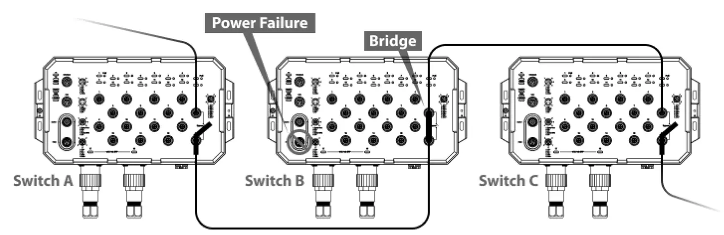
Bypass Function
This Ethernet switch supports bypass function by two Ethernet ports (8 and 16). When one of the Ethernet switches loses power, Ethernet ports (8 and 16) will bypass the power lost Ethernet switch to prevent the network from disconnecting.
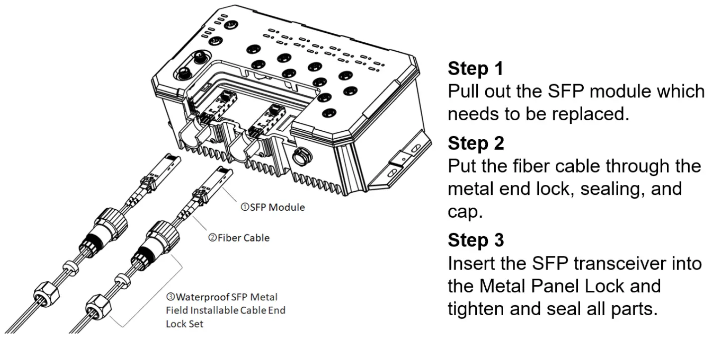
SFP Installation
Wall Mounting Installation
Follow the steps below to mount the switch to a wall using the screw holes.
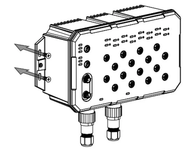
Step 1. Prepare 4 screws for mounting the switch to a wall. (Recommended use the M5 screws.)
Step 2. Based on the positions of 4 screw holes on the left and right side of the switch to make 4 screw holes on a wall accordingly.
Step 3. Insert the screws through the screw holes on the switch and screw the switch into the wall.
Step 4. To remove the switch from the wall, do the opposite from the steps above.
Antaira’s Customer Service and Support
Antaira’s Technical Service & Support Centers:
+ 844-268-2472 (Antaira US Headquarter)
+ 48-22-862-88-81 (Antaira Europe Office)
+ 886-2-2218-9733 (Antaira Asia Office)
Antaira’s Web Sites & Repair/Support Emails:
www.antaira.com / [email protected]
www.antaira.eu / [email protected]
www.antaira.com.tw / [email protected]
Any changes will be announced on the Antaira website.


