![]()
![]()
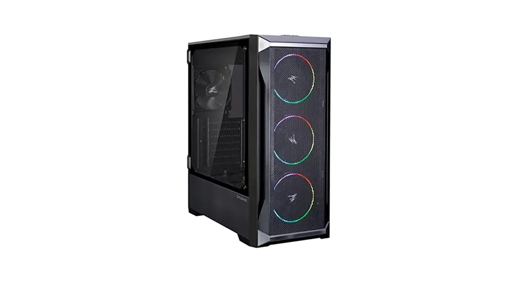
Z8/Z8MS/Z8TG
ATX MID-TOWER
COMPUTER CASE
User’s Manual
* To ensure safe and easy installation, please read the following precaution.
* Product design and specifications may be revised to improve quality and performance without notice.
Ver. 041120
Precautions
- Read this manual carefully before installing.
- Check the product and components before installing. If you find any abnormality, contact the location where you purchased the product for a replacement or refund.
- Wear gloves to prevent accidents when installing the product.
- Severe damage may occur when mounting the system, so do not apply excessive force.
- Connecting the cable incorrectly may cause a fire due to a short circuit. Make sure to refer to the manual when connecting the cable.
- Be careful not to block the ventilation hole of the product when using the system.
- Avoid locations with direct sunlight, water, moisture, oil, and excessive dust. Store and use the product in a well-ventilated location.
- Do not wipe the surface of the product using chemicals. (organic solvents such as alcohol or acetone)
- Do not insert your hand or another object into the product during operation, as this may injure your hand or damage the object.
- Store and use the product out of children’s reach.
- Our company assumes no responsibility for any problem that occurs due to the use of the product for purposes other than its designated purposes and/or the carelessness of the consumer.
- The exterior design and specifications of the product are subject to change without prior notice to consumers for quality improvement.
Specifications
| Model | Z8 | Z8 MS | Z8 TG | |
| Case Form Factor | ATX Mid-Tower | |||
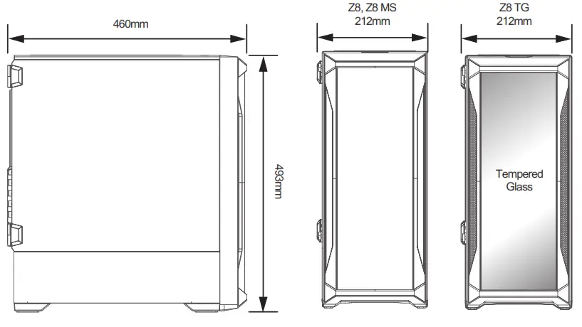
| Dimensions | 460 x 212 x 493(H)mm | |||
| Weight | 6.3kg | 6.8kg | ||
| Case Materials | Tempered Glass, Plastic, Steel | |||
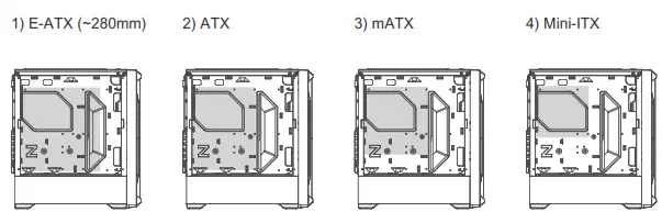
| Motherboard Support | E-ATX(~280mm) / ATX / mATX / Mini-ITX | |||
| Maximum VGA Length | 350mm | |||
| Maximum CPU Cooler Height | 160mm | |||
| Maximum PSU Length | 180mm | |||
| PCI Expansion Slots | 7 | |||
| Drive Bays | 2ⅹCombo (3.5″ or 2.5″, Toolless ), 4ⅹ2.5″ | |||
| Fan Support | Top | 2ⅹ120mm / 2ⅹ140mm | ||
| Front | 3ⅹ120mm / 3ⅹ140mm | |||
| Rear | 1 x 120mm | |||
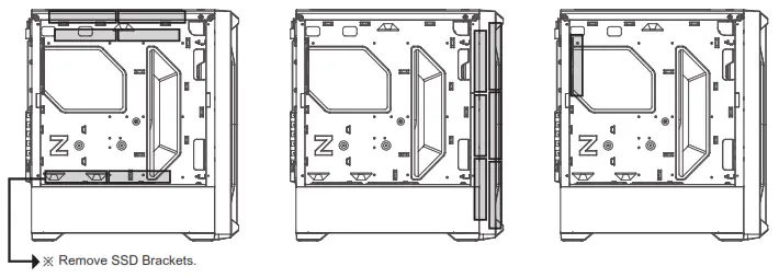
| Bottom | 2 x 120mm (Remove SSD Brackets) | |||
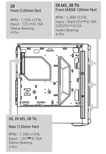
| Fan(s) Included | Front | 3 x 120mm | Addressable RGB 3 x 120mm | |
| Rear | 1ⅹ120mm | |||
| ARGB Controller Included | ||||
| Radiator Support | Top | 120mm / 240mm / 280mm | ||
| Front | 120mm | |||
| Rear | 120mm | |||
| I/O Ports | 2ⅹUSB3.0, 1ⅹUSB2.0, 1ⅹHeadphone Jack, 1ⅹMicrophone jack, Power Button, Reset Button, LED Button | |||
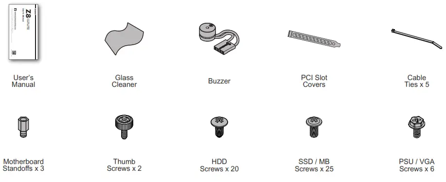
Accessories
I/O Ports
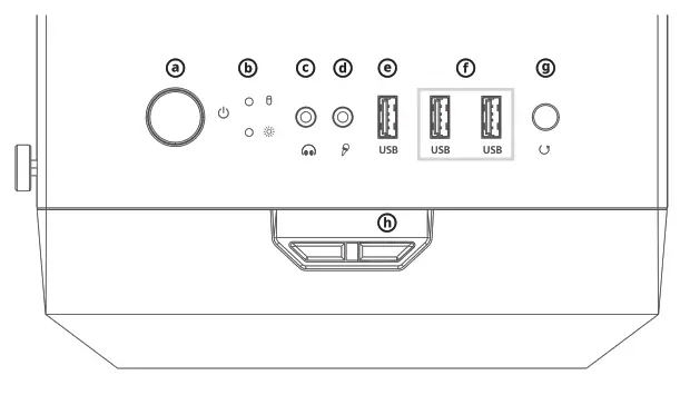
| # | Part |
| ⓐ | Power Button |
| ⓑ | HDD / Power LED |
| ⓒ | Headphone Jack |
| ⓓ | Microphone Jack |
| ⓔ | USB 2.0 Port |
| ⓕ | USB 3.0 Ports |
| ⓖ | Reset Button |
| ⓗ | LED Button |
- Removing the side panels
1) Tempered Glass
2) Steel Panel 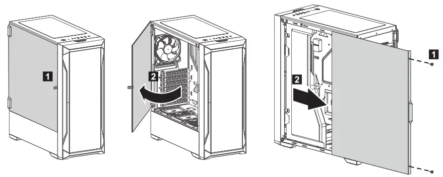 Removing the front panel
- Mounting the motherboard
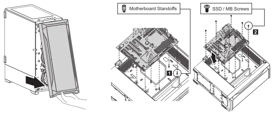 3-1. Motherboard size
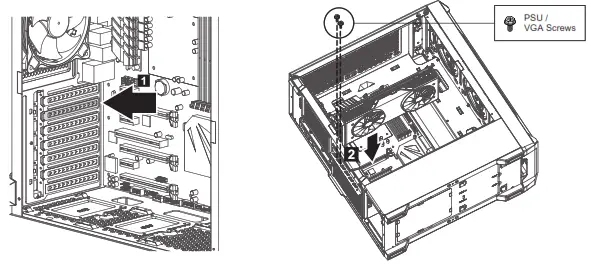
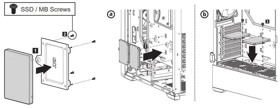
- Mounting the PCI-E(VGA) Card
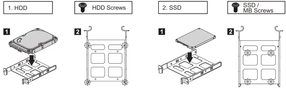
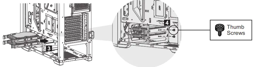
- Mounting the 2.5” SSD
- Mounting the 3.5″ HDD
 ※ Z8 MS, Z8 TG Only
 ※ How to control RGB LED
– LED colors & patterns can be changed by pressing the LED Button on I/O ports.
– Long pressing on the LED Button for 6 seconds, RGB LED will be turned off after blinking twice in white.
– Long pressing on the LED Button for 3 seconds, RGB will be synchronized with the motherboard after blinking once in white.
Press the LED Button again to desynchronize with the motherboard.
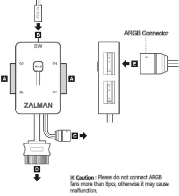
A. ARGB LED 1~4 / 3-Pin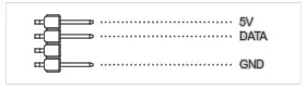 B. ARGB LED Control Button / 2-Pin
– Connector to ARGB LED Control Button
C. Other Motherboards Sync / 3-Pin
– Connector to Motherboard
– Requires Motherboard that Supports RGB Sync ※ Caution: if Addressable 3 Pin connects to a 12V header instead of a 5V header improperly, It may cause fatal damages to the product by the overvoltage.
D. SATA Power / 15-Pin
– Connector to PSU
– Input: 5V E. Connect the ARGB connector to the RGB hub
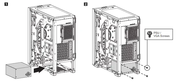
 - Mounting the PSU

- Mounting the radiator
- Mounting the top radiator
・120mm
・240mm
・280mm
- Mounting the top radiator
- Mounting the front and rear radiator
・120mm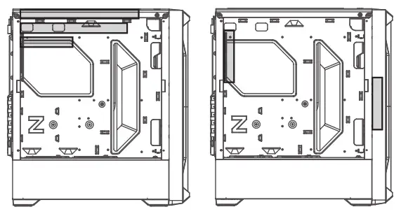
- Fans Included / Specifications

- Mounting the fans
- Mounting the top & bottom fans
・2 x 120mm
・2 x 140mm - Mounting the rear fan
・1 x 120mm - Mounting the front fans
・3 x 120mm
・3 x 140mm
- Mounting the top & bottom fans
- I/O Connectors
 ※ How to control RGB LED
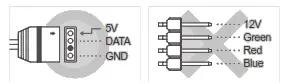 ※ Caution: if Addressable 3 Pin connects to a 12V header instead of a 5V header improperly, It may cause fatal damages to the product by the overvoltage.
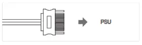 E. Connect the ARGB connector to the RGB hub