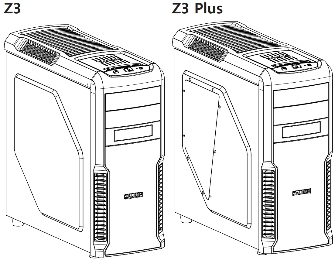
ZALMAN Z3 Series ATX Mid Tower PC Case
Contents hide
Cautionary Note
- Please read this manual thoroughly prior to installation.
- Before installing, check the components and condition of the product, and if any problem is found, contact the retailer.
- Please wear gloves while handling this product to prevent injuries.
- Incorrect cable connections may cause short circuits leading to fire hazards.
- Do not block the front intake vent or the rear exhaust vent.
- Keep this unit away from heat sources, direct sunlight, water, oil and place the unit on a flat and well-ventilated area.
- Do not clean the product surface with chemicals or wet cloth. (chemicals: industrial alcohol, pait thinner and organic solvent etc.)
- Avoid inserting objects or hands into the system while it is in operation to prevent product damage and injuries.
- Zelman Tech Co., Ltd. is not responsible for any improper use.
- Product design and specifications may be revised to improve quality and performance.
Components
Components
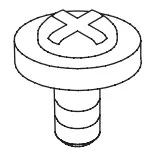
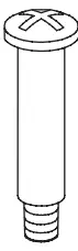
- A Bolt (#6-32*5mm) x 13 [PSU,PCI]

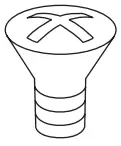
- B Bolt (M3*5mm) x 25 [M/B,FDD,SSD,ODD]

- C Bolt (FAN) x 4 (BH M3*28mm)

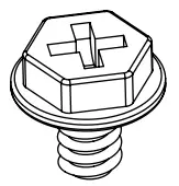
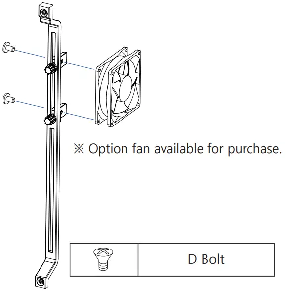
- D Bolt (FAN) x 2 (FH Tap5*10mm)

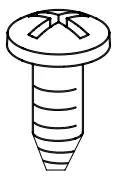
- E Bolt (M3*5mm) x 4

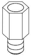
- Stand Off x 6

- Cable Tie x 5

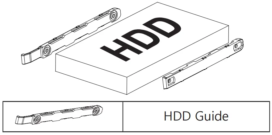
- HDD Guide

- Manual x 1


Z3 Plus Components
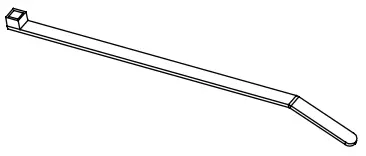
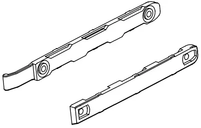
- VGA Guide x 1

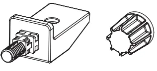
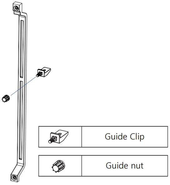
- Guide Clip x 2

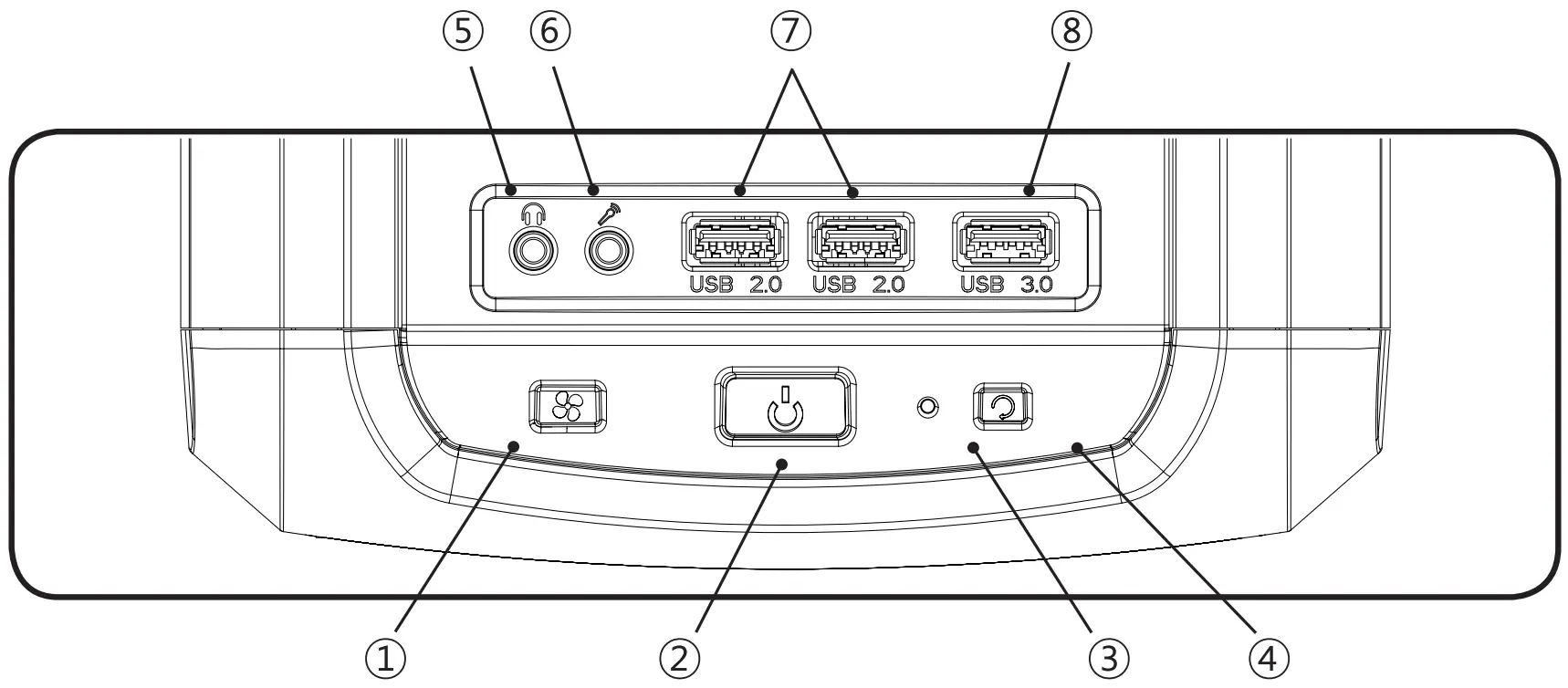
Front I/O Ports
# | Part |
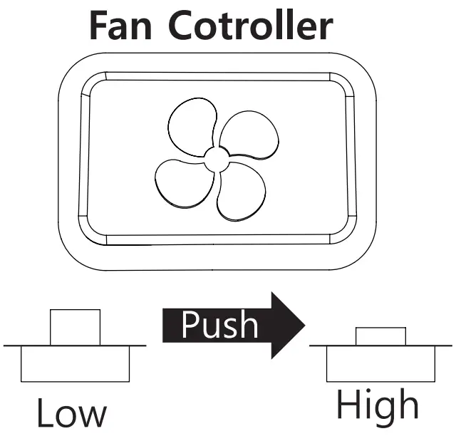
| ① | FAN Controller |
② | Power Button |
| ③ | HDD LED |
④ | Reset Button |
| ⑤ | Headphones |
⑥ | Mic |
| ⑦ | USB 2.0 |
⑧ | USB 3.0 |
Installation
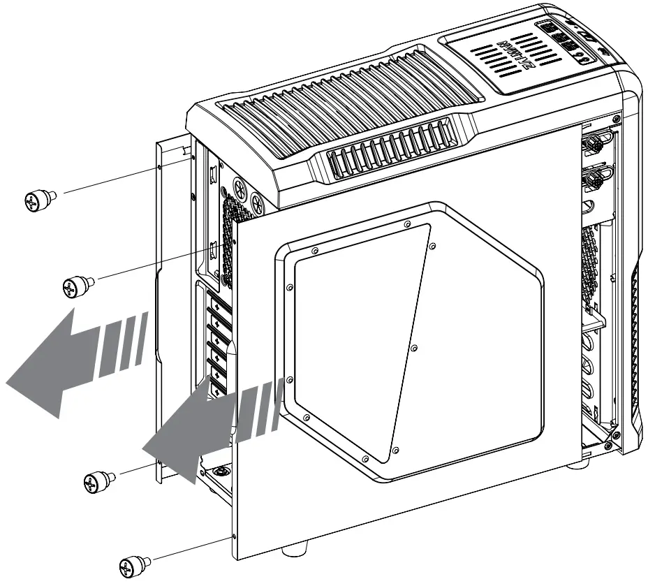
Side Panel Removal
Motherboard Installation
There are 6 Stand-offs preinstalled. Please refer to the diagrams below for additional Stand Off positions (based on motherboard type).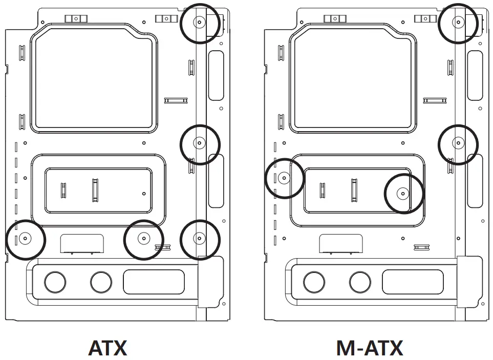
VGA Card Installation
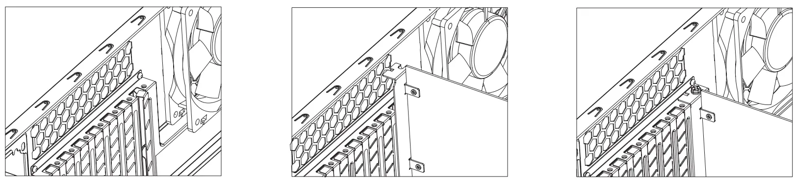
 | A Bolt |
① Unfasten the Hand Screw holding the PCI Cover and disassemble the cover.
② Remove the PCI Slot Cover.
③ Install the VGA Card and fasten with a fixing screw.
Tip
- The VGA Support system is designed to support the weight of high profile vedio cards to prevent warping.
– Assemble the clip and the nut as shown
– Install the Fan on the assemble clip as shown
5.25″ and 3.5″ Drive Installation
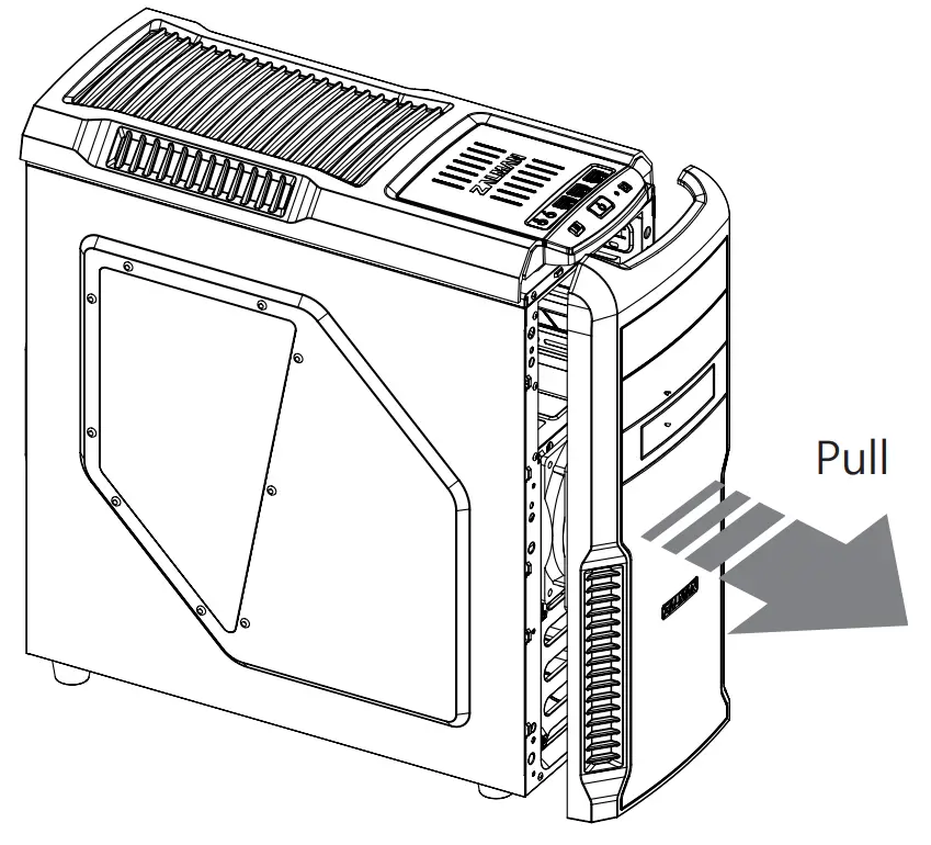
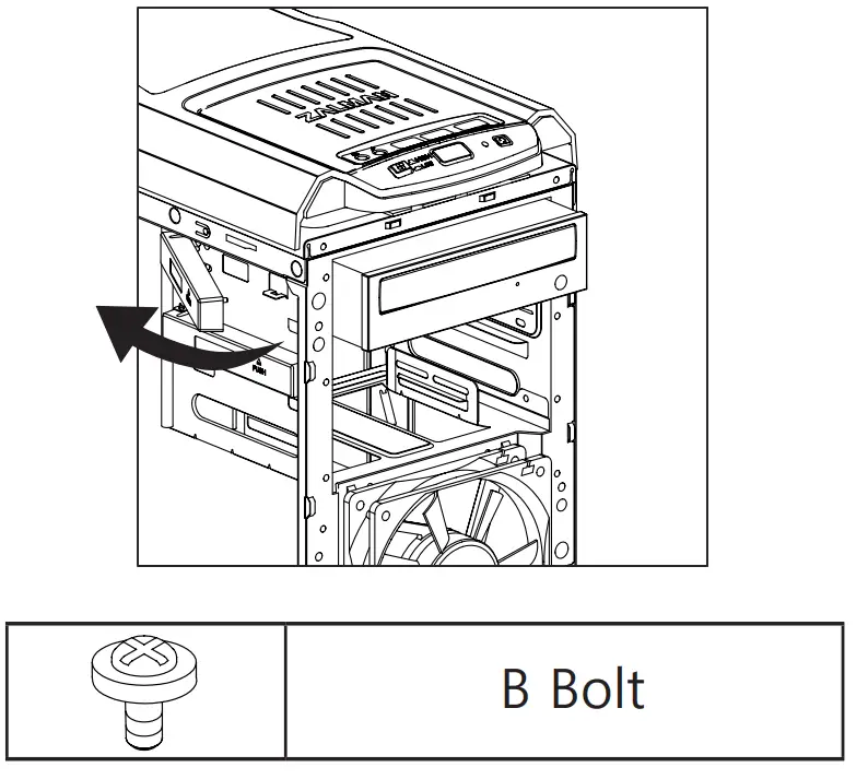
- Front Cover removal

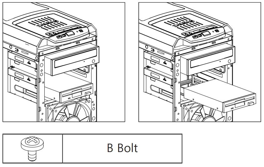
- ODD Installation

- 3.5 Installation

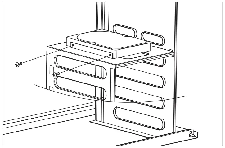
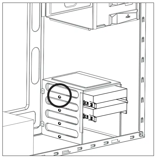
3.5″ HDD Installation
- Use the HDD Guide to install 3.5″ HDD.

- When transporting an assembled system, please secure the HDD with Bolt E as shown above.

E Bolt
Cable Connection
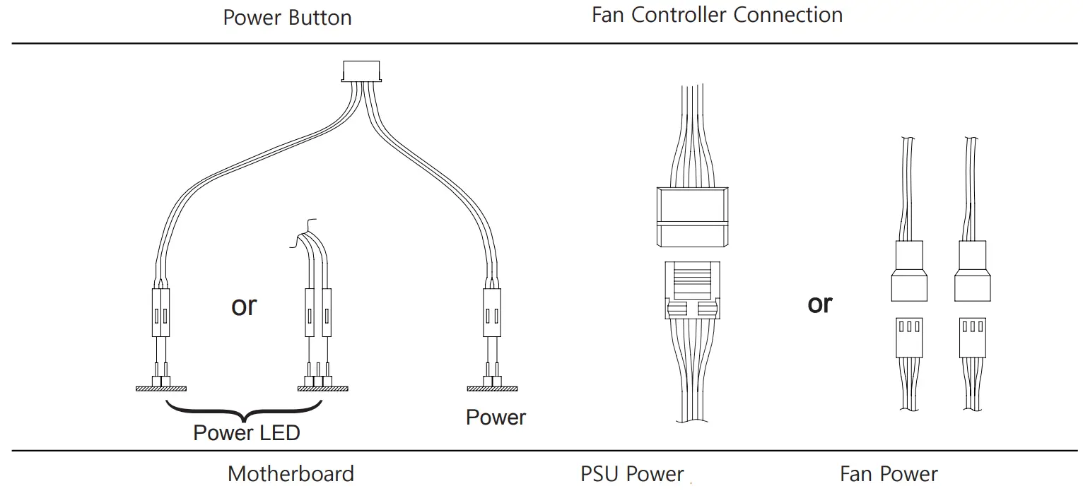
I/O Port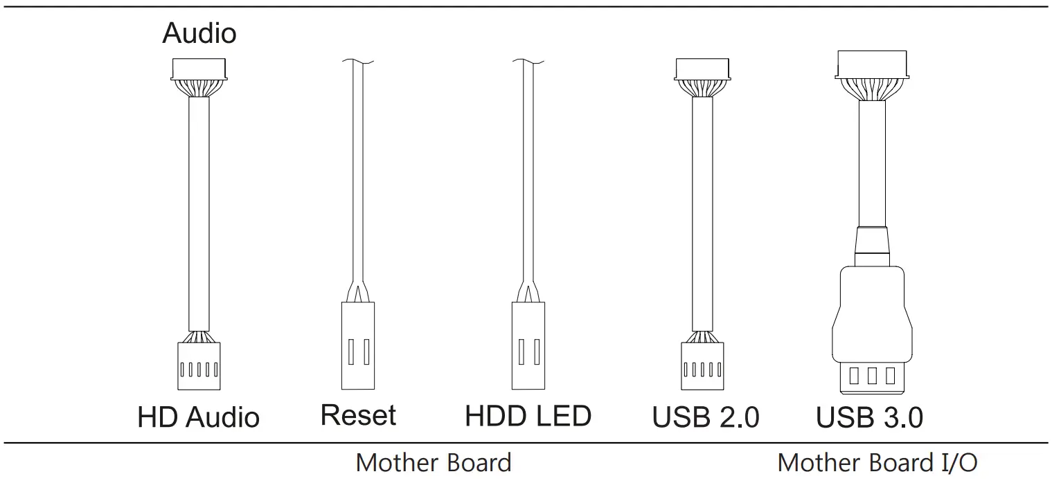
2.5″ HDD and SSD Optional
- 2.5″ HDD and SSDs can be installed on the right side of case as shown in the diagram below.

B Bolt