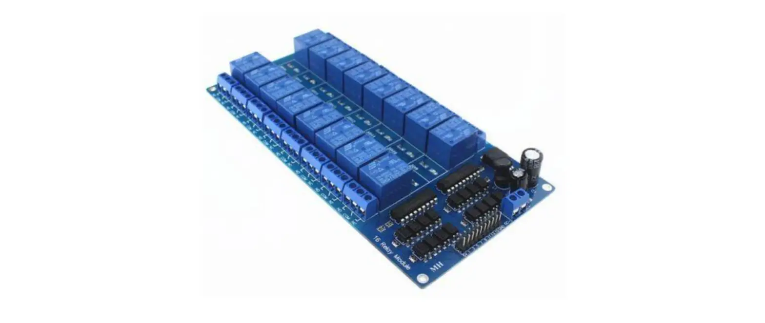
altus 16 DO Relay Module NX2020
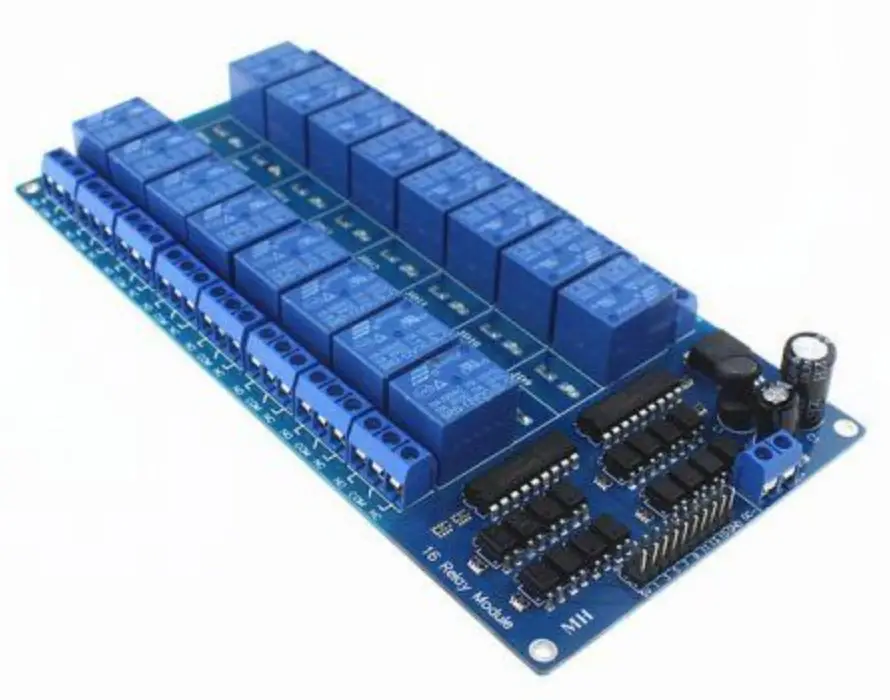 Installation Guide
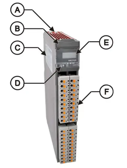
- Fixing locks
- Module slot locking slider
- Label for module identification
- Diagnostic LED and switch
- Status and diagnostic display
- 10 pin terminal blocks
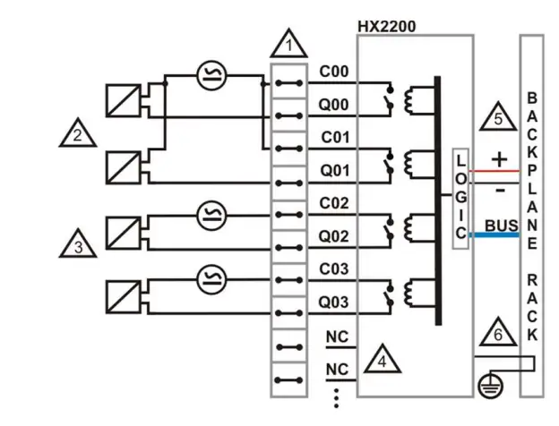
Steps
- Set of terminal blocks
- Typical usage of digital output using the load power supply to a group of digital outputs
- Typical usage of dry contact digital output using the load power supply to each one of the outputs
- Unused terminals on the connector module
- The module power supply comes through the backplane and does not require external connections
- The module is connected to the protection earth through the backplane rack
TERMINAL MAPPING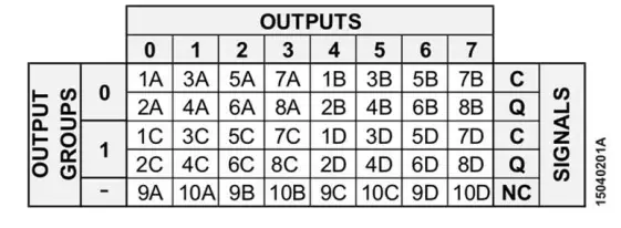
Features
- Maximum Voltage of Power Supply Load: 240 Vdc / 250 Vdc
- Current Consumption from Backplane Rack Power
- Supply: 980 mA
Installation
- Digital Output Terminals: 2A, 4A, 6A, 8A, 2B, 4B, 6B, 8B, 2C, 4C, 6C, 8C, 2D, 4D, 6D and 8D
- Common Output Terminals: 1A, 3A, 5A, 7A, 1B, 3B, 5B, 7B, 1C, 3C, 5C, 7C, 1D, 3D, 5D and 7D
- Not connected terminals: 9A, 10A, 9B, 10B, 9C, 10C, 9D and 10D
- The module is grounded through the backplane rack.
HX9402 – 10 pin terminal block
Warning:
Products with broken warranty seal are not covered in warranty.
Cautions:
- The device is sensitive to static electricity (ESD).
- Always touch in a metallic grounded object before handling it.
- Hadron Xtorm Series can operate with voltage up to 250 Vac.
- Special care must be taken during the installation, which should only be performed by qualified technical personnel.
- Do not touch the field wiring when in operation.
information
For further information about programming or installation, see the Product Datasheet (CE123400) or the Utilization Manual (MU223600) available on Altus website.


